Assignment 5-RADIOSS Interfaces & Study of Effect of Notches Challenge
Aim: To mesh the Bumper Model using Hyper mesh and run the simulation on crush tube by using RADIOSS.
OBJECTIVE:
- To mesh the bumper as per given quality criteria.
- To run the simulation for crush tube model as it is with default failure parameters.
- To run the simulation by changing the parameter Inacti=6.
- To run the simulation by creating type 11 contact parameters.
- To run the simulation by removing both notches and boundary conditions on rigid body node.
- To run the simulation by creating new notch at middle and boundary conditions on rigid body node.
- To create a new notch with nodes only from opposing two faces and run.
First Model: Bumper
PROCEDURE/STEPS: -
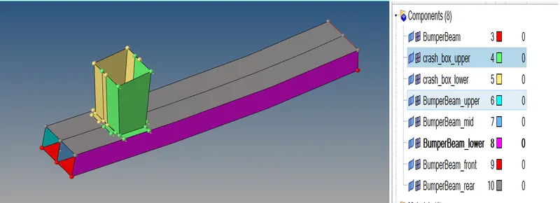
- import the Model file
Here we have Bumper we need to open the model in Hyper mesh GUI.
Command: File >> Import >> Model >> Locate the file directory >> hit Open >> hit Import.
- Quality Criteria setting:
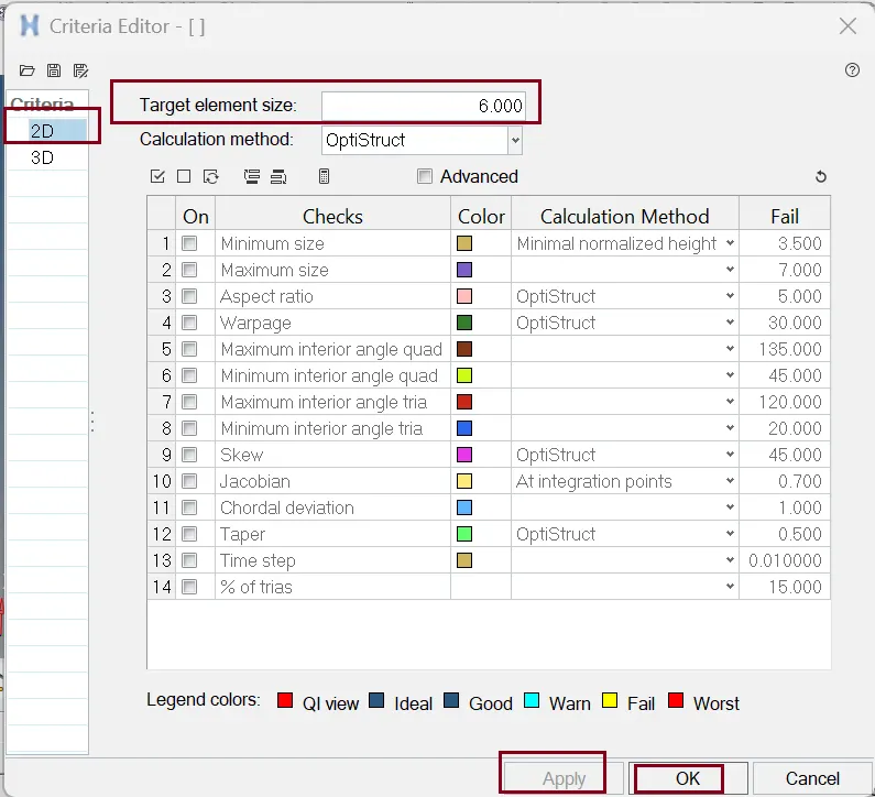
Now we want to start surface Meshing on the Component. Before meshing we need to set quality criteria.
Command for setting Quality Criteria: Preference >> Criteria file setting >> Edit the card as per figure below >> hit Apply >> ok.
- 2D meshing:
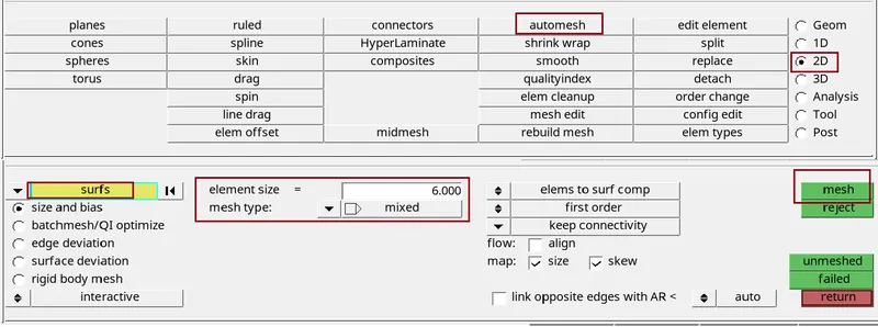
Now we start the surfaces meshing for this we use....
Command: 2D >> automesh >> edit the tab as per figure below >> select the surface >> hit mesh >> hit middle mouse click. We can also access this tab by pressing F12 key.
Things need to be ensured while meshing
- Avoid back-to-back trias.
- Avoid opposite trias.
- Avoid trias element at the edges.
- To fix Elements quality Criteria and trias are removed by using Tool >> edit element, >> split, >> replace, >> elem clean up.
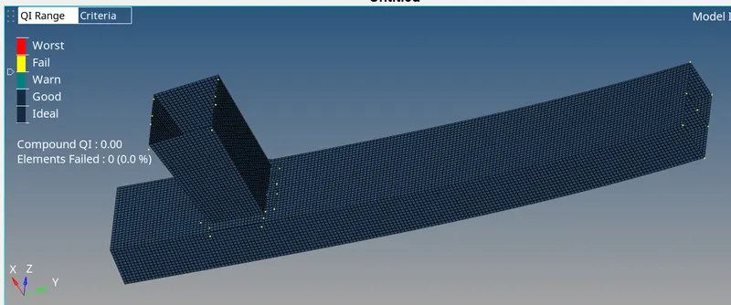
Mesh results:
MODEL:2 Crash Tube
{CASE:1}
Here we Run the crash tube model as it is.
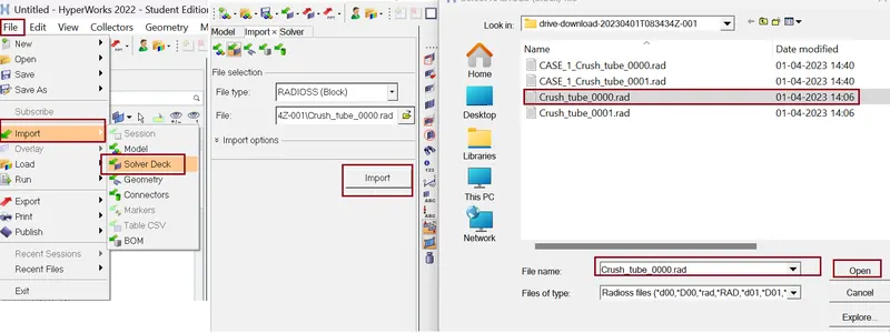
- Import the model
Here we import the Model in RADIOSS {solver deck}.
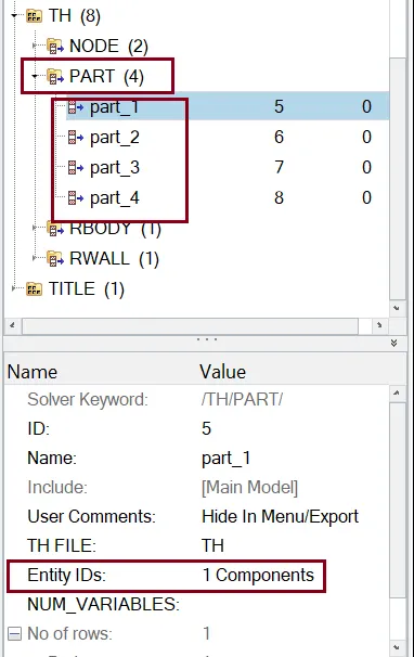
- Creating time history (TH/PART) Card
Now we create the THPART (time history part) we have to click on the output Blocks and create the TH PART, and select all four components one by one and click on ok. Then the TH part is created.
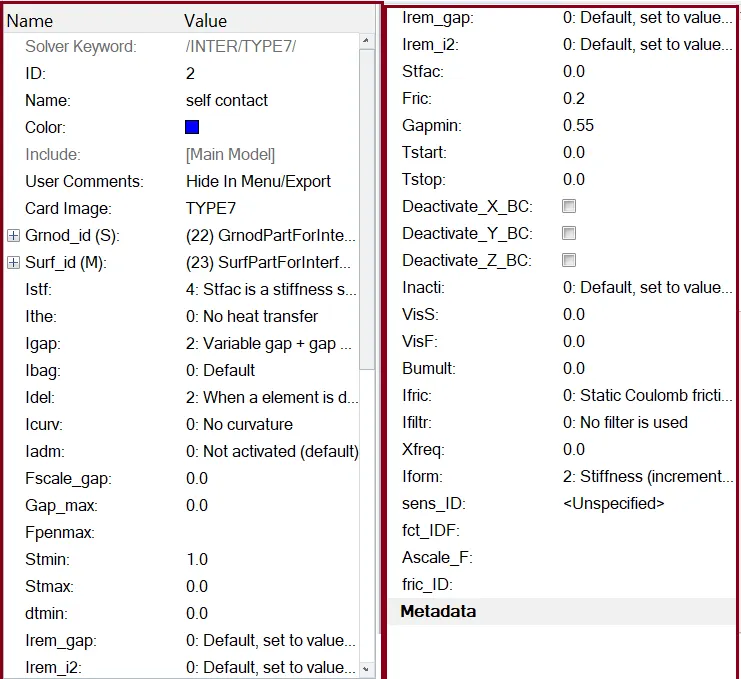
- Self-contact card
By default, TYPE7 Interface /contact modelling has been assigned. TYPE7 supports variable stiffness with node to surface contact.
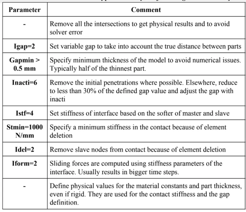
Recommended parameters for Type7 contact
- Simulation
Now we will run the simulation by using Tool Analysis >> Radioss >> Edit the card as per figure below.
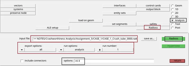
Click Radioss and simulation starts running after some time, it will show JOB IS COMPLETED
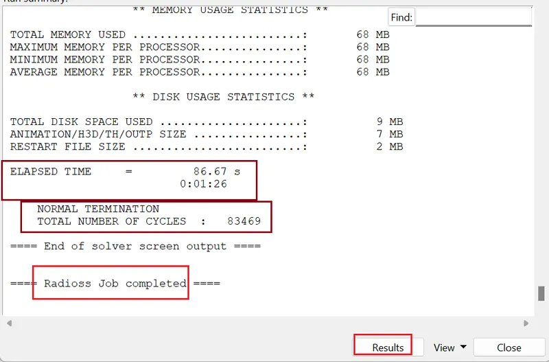
- Checking energy error and mass error:
we need to check the output of simulation in 0001.out file
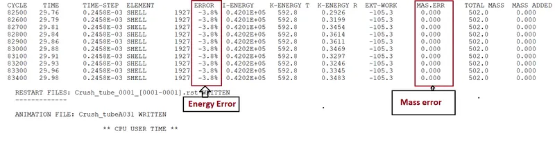
From output file energy error is -3.8% and mass error is 0% .
- Condition for acceptable result
- The error {Energy} must be less than – 15 % at the end of computation (0% for a good model setup).
- The error {mass} must be less than 2%.
So, from output data our both the condition is satisfy we go for plots.
For plots we need to open hypergraph 2D and browse file as data from TA01 file.
- Internal Energy plot
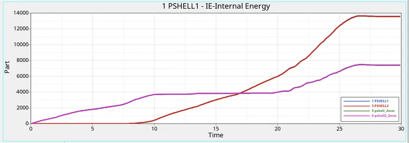
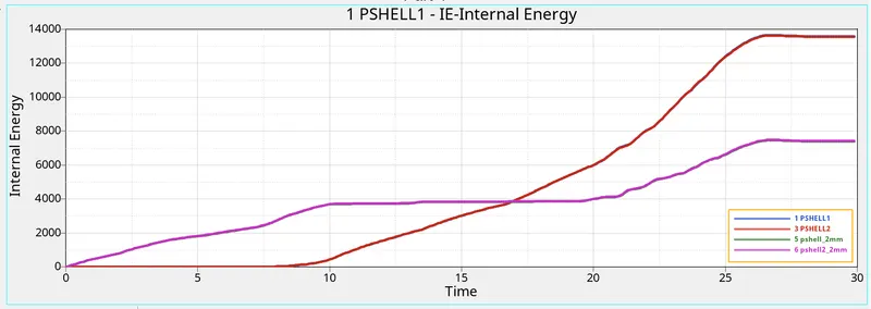
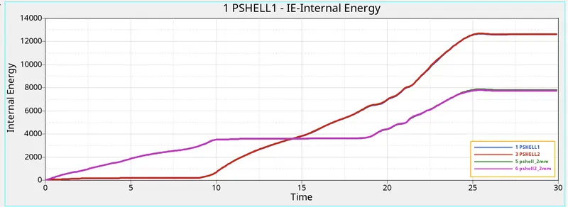
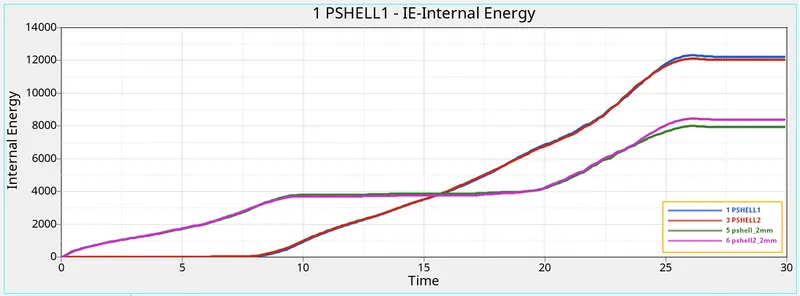
The Internal energy for the PSHELL_2 components is increasing at the beginning because it is attached to the rigid wall and deform smoothly at the notch area where as the stiffness is less at these parts. The Internal energy for the PSHELL_3 components is zero for 9ms and linearly increasing to deform (compression takes place) and the stiffness is high for these parts because of flat surface area.
- Kinetic Energy plot
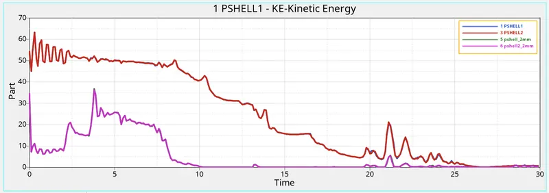
- Contact Energy plot
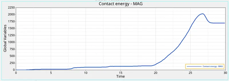
- Rwall Force
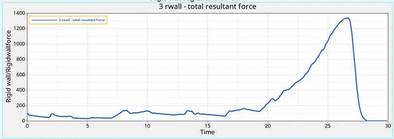
- Vonmises stress
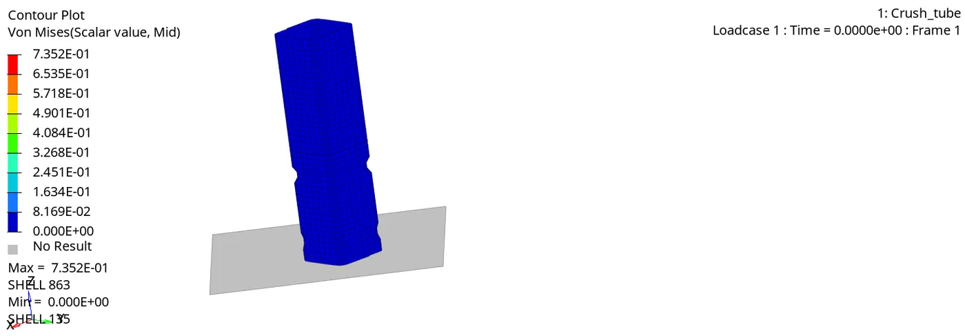
{CASE:2}
- In this case, we have to change the Inact = 0 to Inacti =6.
- Inacti = 6 will remove any initial penetration present.
To change this click on Solver browser >> Interface >> Type7 >> Inacti.
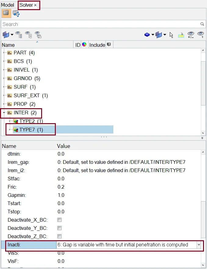
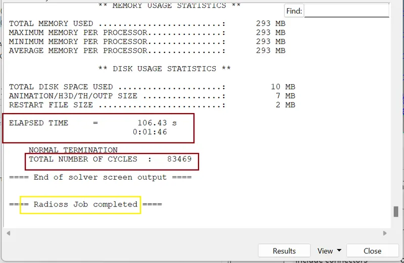
After this, we need to run the simulation. The procedure is same as earlier.
JOB IS COMPLETED
- Checking energy error and mass error:
we need to check the output of simulation in 0001.out file
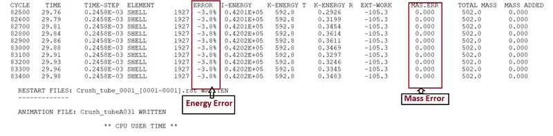
The Energy error is -3.8% and Mass error is 0% which is acceptable.
- Internal Energy plot
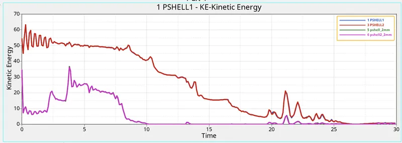
- Kinetic Energy plot
- Contact Energy plot

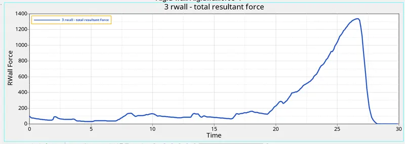
- Rwall Force
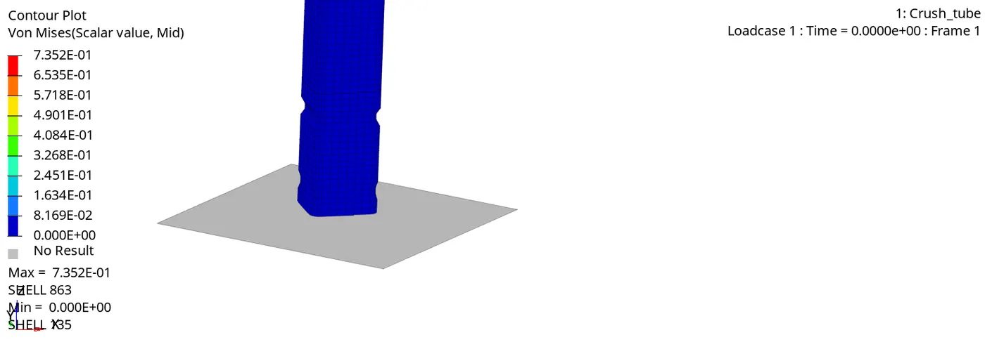
- Vonmises stress
{CASE:3}
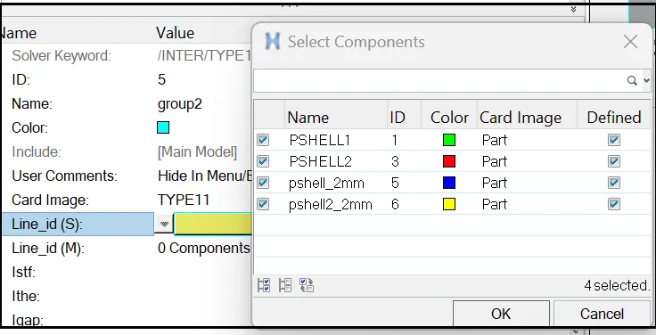
For this case, we have to create Type11 contact
So, we have both Type7 and Type11 contact
For creating type11 contact we use command: View >> Browser >> HyperMesh >> Solver >> INTER >> right click Over INTER >> Create >> Type11 >> select slave( line_id(S)) and Master (line_id(M)) .
And edit the card as figure below.
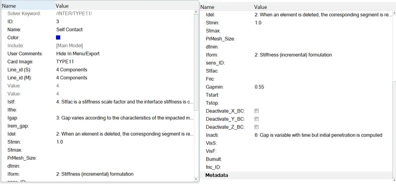
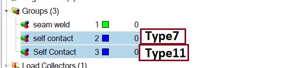
After this, we need to run the simulation. The procedure is same as earlier.
JOB IS COMPLETED
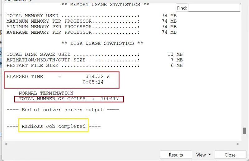
- Checking energy error and mass error:
we need to check the output of simulation in 0001.out file
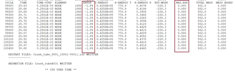
The Energy error is -1.8% and Mass error is 0% which is acceptable.
- Internal Energy plot
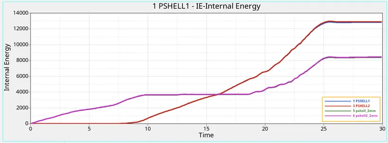
- Kinetic Energy plot
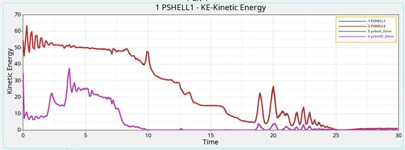
- Contact Energy plot
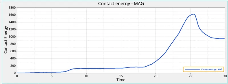
- Contact Force plot
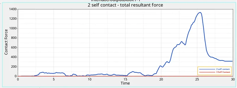
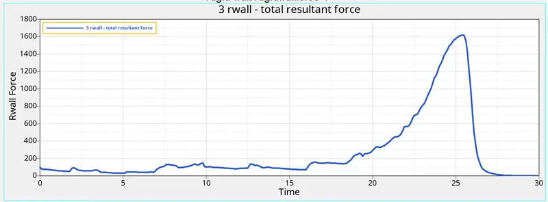
- Rwall Force
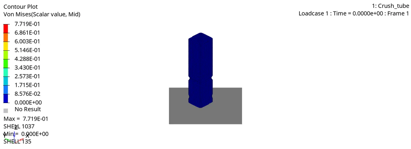
- Vonmises stress
{CASE:4}
Here, we have to remove both the notches and the boundary conditions on the rigid body and run the simulation. To remove the notches, we can use align option from the node edit option.
With the help of node align we can remove both the notches.
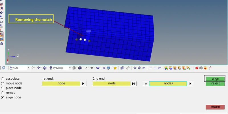
After removal of Notch
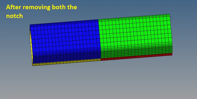
- Edit boundary conditions
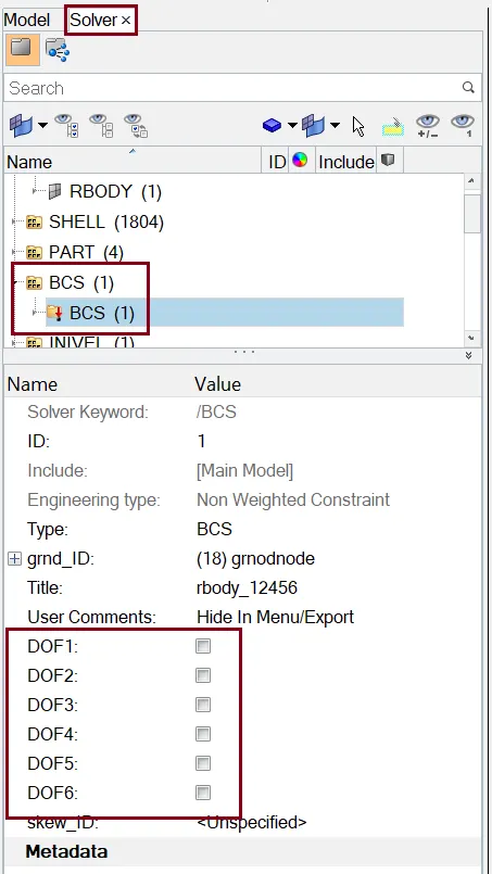
After this, we need to run the simulation. The procedure is same as earlier.
JOB IS COMPLETED
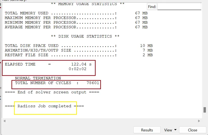
- Checking energy error and mass error:
we need to check the output of simulation in 0001.out file
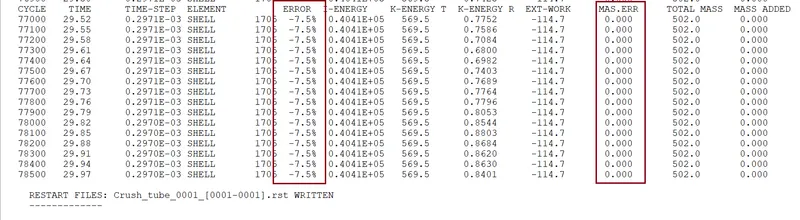
The Energy error is -7.5% and Mass error is 0% which is acceptable.
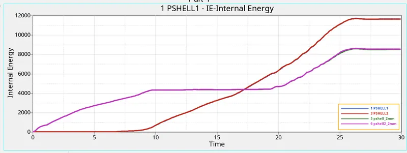
- Internal Energy plot
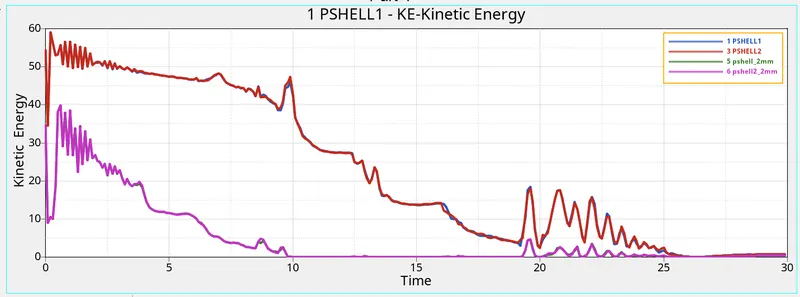
- Kinetic Energy plot
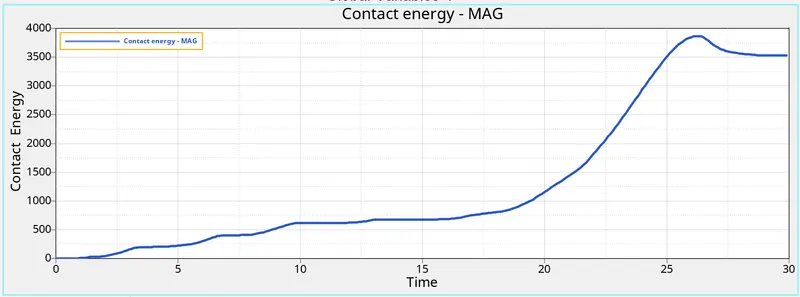
- Contact Energy plot
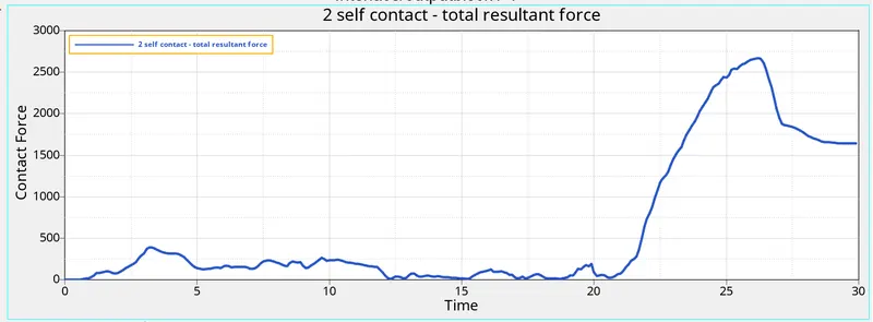
- Contact Force plot
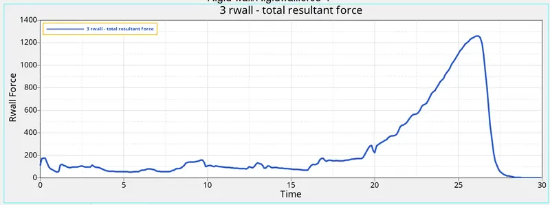
- Rwall Force
- Vonmises stress
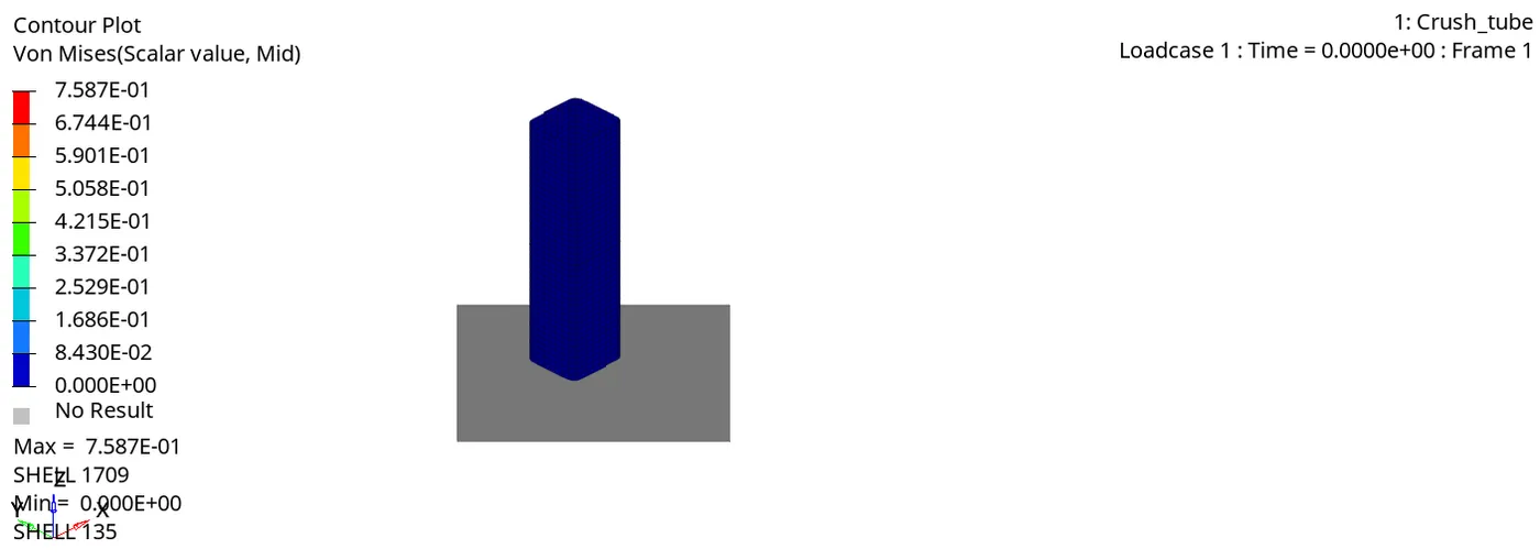
{CASE:5}
In this case, we have to create a new notch in the centre and run the simulation.
We can create notch by using node align option.
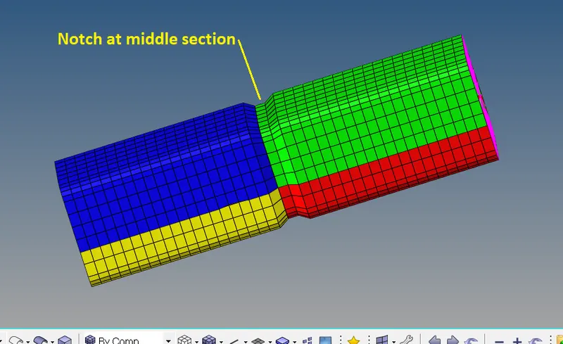
After that, we run the simulation. The procedure is same as earlier.
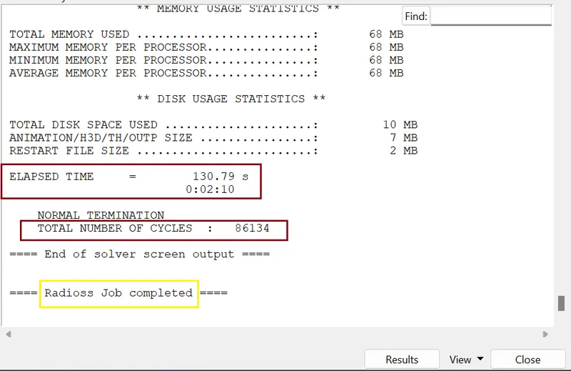
JOB IS COMPLETED
- Checking energy error and mass error:
we need to check the output of simulation in 0001.out file
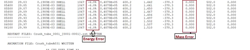
The Energy error is -6% and Mass error is 0% which is acceptable.
- Internal Energy plot
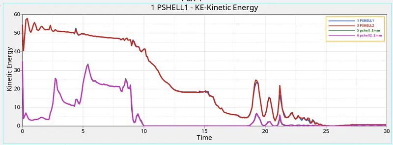
- Kinetic Energy plot
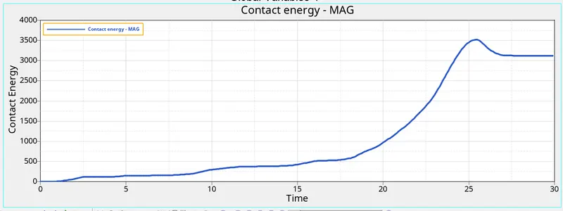
- Contact Energy plot
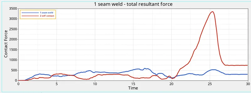
- Contact Force plot
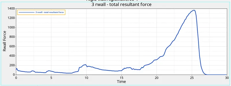
- Rwall Force
- Vonmises stress
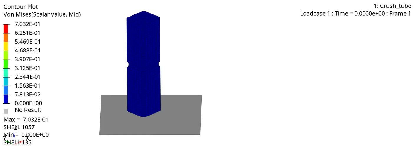
after impact, deformation is first observed in the middle in the portion where the notch is.
{CASE:6}
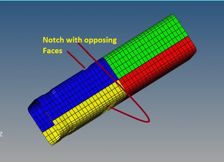
In this case we have create new notch with nodes only from Opposing two faces.
Similarly as previously we use node align tool to create opposing two face notch.
After that, we run the simulation. The procedure is same as earlier.
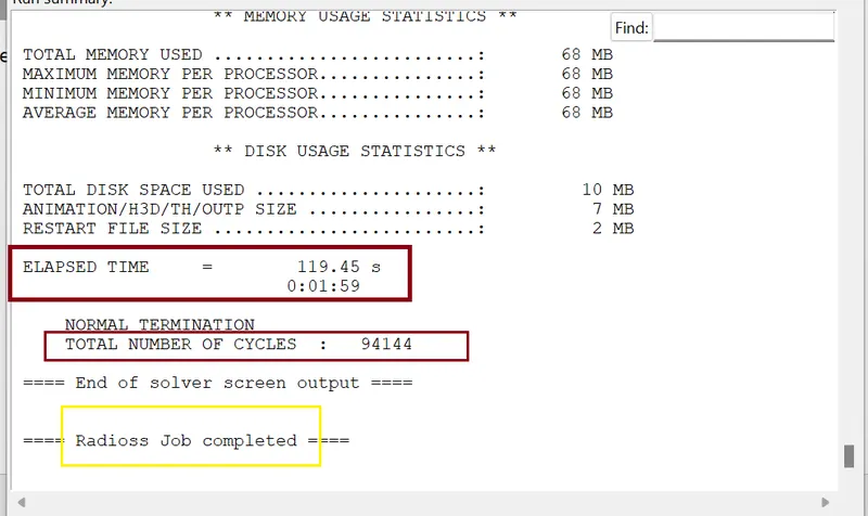
JOB IS COMPLETED
- Checking energy error and mass error:
we need to check the output of simulation in 0001.out file

The Energy error is -6.2 % and Mass error is 0% which is acceptable.
- Internal Energy plot
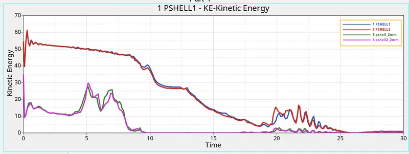
- Kinetic Energy plot
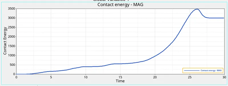
- Contact Energy plot
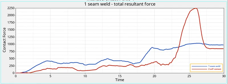
- Contact Force plot
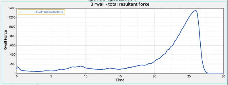
- Rwall Force
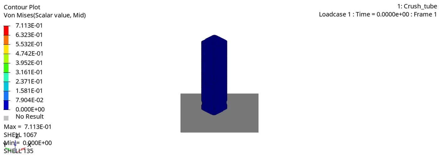
- Vonmises stress
COMPARISON
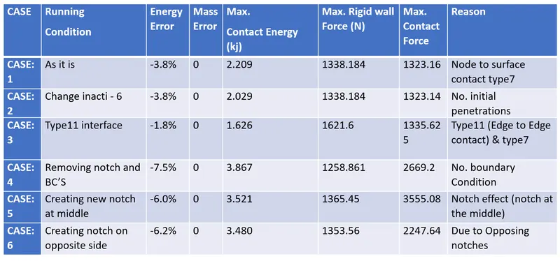
Comparison of energy errors, mass errors, Max. Contact force, Max. Rigid wall force and Max. Contact energy are given in below table
CONCLUSION
- We observed here in CASE:4, where the notch is removed, the stress induced in the crush tube is the least compared to other cases. The crush tube with notches undergoes stress concentration and these areas are the first to undergo deformation.
- The deformations are predictable in case of notched components.
- No initial penetration is observed in CASE: 1 where Inacti = 0.
- If initial penetration existed, it could have been indicated by the graph of contact energy which could have picked up at the start itself before any impact. Energy error for all cases is between -7.5% to -1.8 % which is acceptable.
************************************************************************************************************************************************************************************************************************************************************************END
Thanks & regards,
DEVESH KASHYAP