Week 8 Worm Gear Challenge
OBJECTIVE:-
To perform a transient structural analysis for Worm gear assembly and determine the results for Equivalent stress, Equivalent elastic strain and the total deformation.
THEORY:
- Worm gears are widely used in power transmission systems due to their high efficiency, compact size, and ability to transmit large amounts of torque. Transient analysis of worm gears is important for understanding their dynamic behaviour and performance under different operating conditions.
- In transient analysis, the motion of the worm gear system is studied over a period of time, taking into account the effects of inertia, friction, and other factors that can affect its behaviour. The analysis can be performed using mathematical models and simulation tools.
- One important consideration in worm gear theory for transient analysis is the contact between the worm and the gear teeth. As the worm rotates, it engages with the gear teeth and transmits torque to the system. The contact between the worm and gear teeth generates friction, which can result in wear and damage to the gear teeth over time.
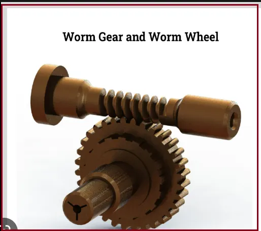
- To analyse the effects of friction in worm gear systems, researchers often use models that take into account the deformation and stress in the gear teeth, as well as the frictional forces between the surfaces. These models can be used to predict the life expectancy of the gear system and optimize its design for maximum performance and durability.
- Other factors that may be considered in transient analysis of worm gears include the effects of backlash, or the play between the teeth in the gear system, as well as the effects of any external forces or vibrations that may impact the performance of the system.
- Overall, worm gear theory for transient analysis is an important area of study for engineers and researchers working on power transmission systems. By understanding the dynamic behaviour of worm gears under different conditions, they can design more efficient and durable systems that can meet the needs of a wide range of applications.
Transient Analysis: - transient analysis in ANSYS Workbench is a powerful tool for simulating the behaviour of a system over time. It is widely used in engineering applications to investigate the response of a system to time-varying inputs. ANSYS Workbench provides a range of analysis tools to perform transient analysis, including explicit and implicit solvers. The transient analysis workflow in ANSYS Workbench involves defining the geometry, material properties, boundary conditions, transient analysis settings, running the simulation, and analysing the results.
ANALYSIS SETUP:
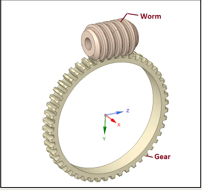
- Here we will start our work Transient structural Analysis of Worm Gear, in which there is an assembly of a Worm and Worm gear.
- We will apply the rotation to the Worm and check the deformation, stress etc on transmission of motion from Worm-to-Worm gear.
- Given Geometry
- Mesh:
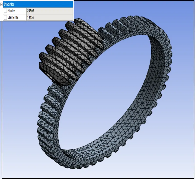
Details:
- Global Element Size: 1.5 mm
- Use Adaptive Sizing: No
- Quality >> Smoothing - Medium
- Material {Structural Steel}
- Density: 7850 Kg/m3
- Young’s Modulus: 2 E+05 MPa
- Poisson’s Ratio: 0.3
- Tensile Yield Strength: 250 MPa
- Compressive Yield Strength: 250 MPa
- Tensile Ultimate Strength: 460 MPa
Initial steps
- Import model in Transient Structural in Geometry section.
- Then go to Mechanical model section.
- Rename the Parts of the setup as Worm and Gear as shown in above geometry.
- Connections:
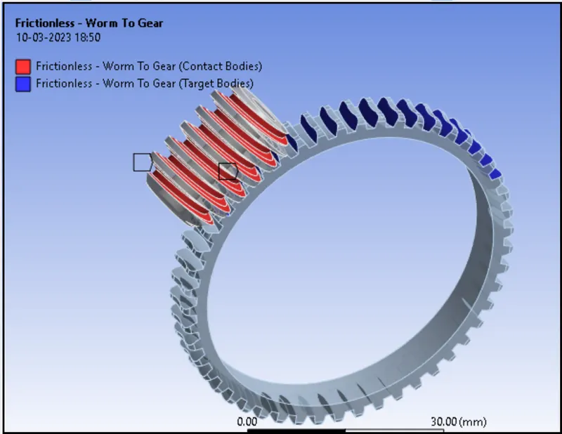
Contacts:
Contact 1st one
- Worm to Gear
- Type: Frictionless
- Contact Body - Worm
- Target Body - Gear
Joints:
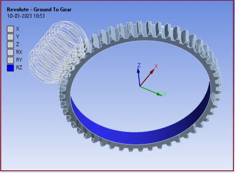
Joint: 1st
- Connection Type: Ground to Gear
- Type: Revolute
- Body: Gear
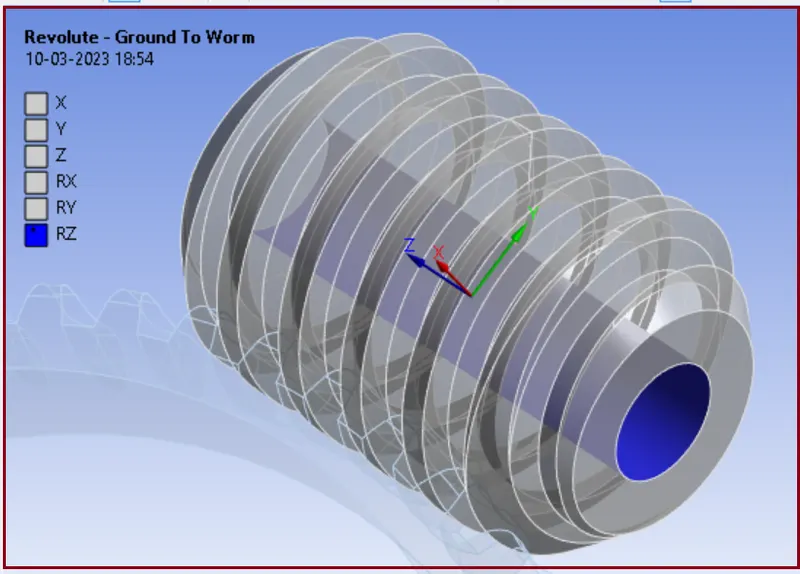
Joint 2nd
- Connection Type: Ground to Worm
- Type: Revolute
- Body: Worm
- Boundary Conditions settings:
Our next step is creating Boundary Conditions:
Analysis Settings:
- No. of Steps: 15
- Solver Type: Program Controlled
- Weak Springs: Program Controlled
- Large Deflection: ON
- Auto Time Stepping: ON
- Defined By: Time
- Initial Time Step: 0.2 s
- Minimum Time Step: 0.2 s
- Maximum Time Step: 0.5 s
- Output Controls: Stress, Strain, Contact Data, Nodal Forces, Volume & Energy, Euler Angles, General Miscellaneous put Yes.{ except Contact Miscellaneous}
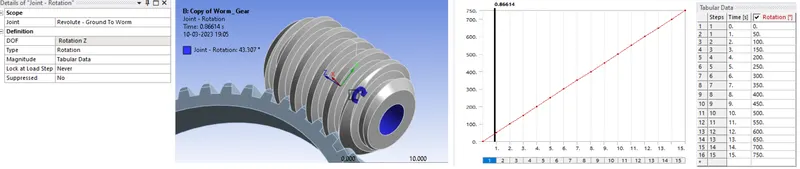
Joint Rotation:
Here we Apply Joint rotation to Worm in order to transform the rotary motion from Worm to Gear.
SOLUTION
After giving proper boundary conditions, create desired solutions for output results.
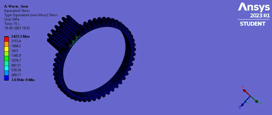
- Equivalent Stress
- Equivalent Elastic Strain
- Total deformation
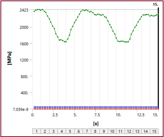
- Stress
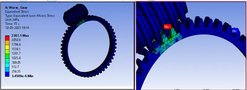
- Stress plot
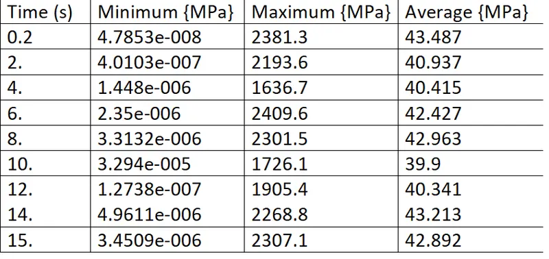
- Detailed Stress data
Comments:
- The change in this type of stress graph is due to engagement and disengagement of the teeth of the Gear with the Worm.
- Here from the Solution data, we can see that the stress on the teeth of Worm and Gear is increasing and decreasing in a cyclic manor.
- Increase and decrease in the stress is nearly similar.
- During the transmission of the motion, higher stress is generating
- We can see the higher stress are concentrated at the edges or contact portion of the teeth or we can say the contact faces of the Worm and Gear are facing high stress.
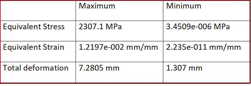
- Stress is generating very high up to 2307.1 MPa.
- Since the value of the stress is exceeding the Yield Strength of the Structural steel, it can fail.
ANNIMATION....
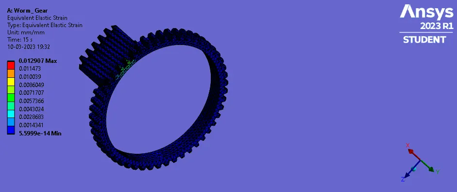
- Elastic strain
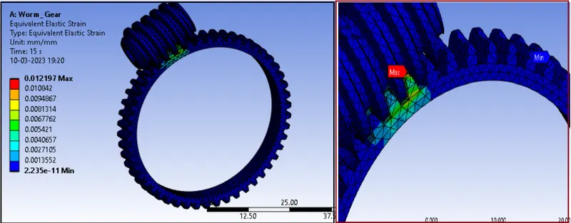
- Elastic Strain plot
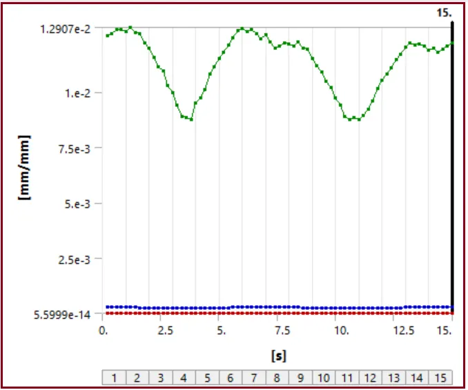
- Detailed strain data
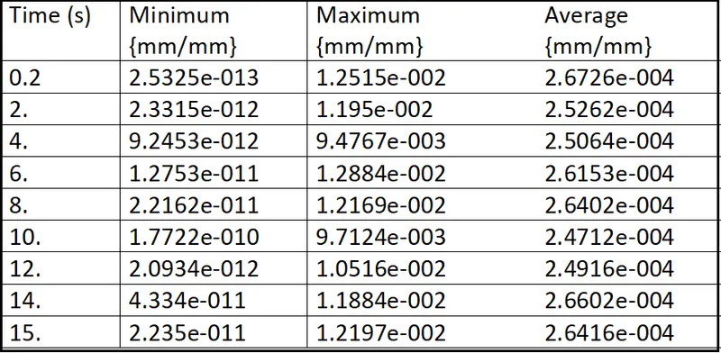
Comments
- Strain curve behaviour is similar as we see in stress curve.
- Here we can see the Max. Strain value is 0.012197
- the rate of the strain is not so high. We can see some spikes in the graph where the strain is increasing, so the amount of percentage elastic strain for failure is low.
- So, the failure of the Worm or Gear Teeth is not happening at higher strain rate or due to plastic strain.
ANNIMATION....
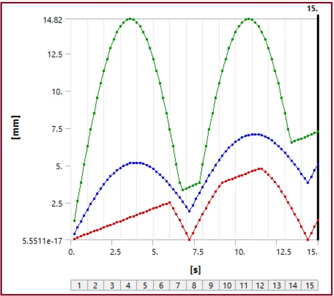
- Total deformation
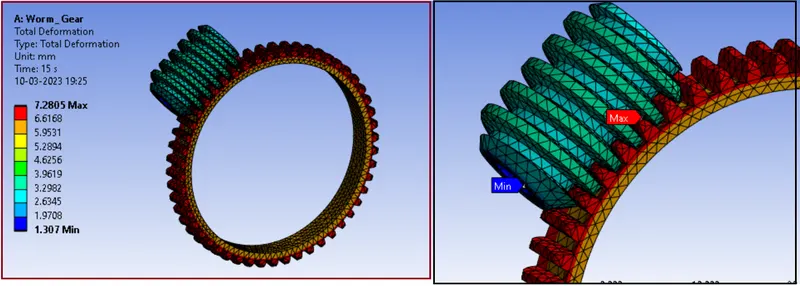
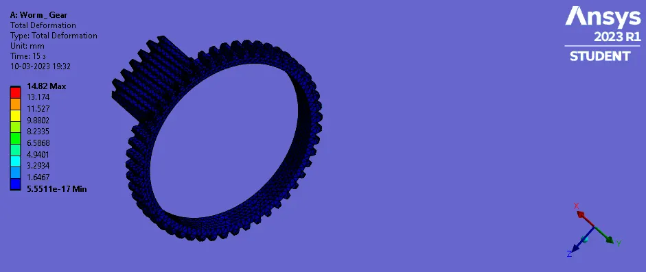
- Deformation Plot
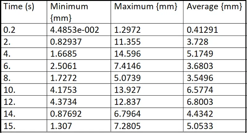
- Detailed deformation Data
Comments:
- Here we gave the rotation motion to the Worm up to 15 s or up to 750 degrees.
- The deformation will not be higher for Worm, but higher deformation will take place to the Gear, as it is big in size and for one rotation or 750 degrees of the Gear, number of rotations of the Worm will be more, so the larger deformation in terms of displacement can be seen at Gear.
ANNIMATION...
Result Summary:
CONCLUSION
- Here we can conclude that the Worm and Gear assembly should be made out of different material to minimize the stress to reduce the loss of efficiency.
- Generally, the Worm and Worm Gear are used with different material to reduce friction and for better transmission.
- Due to sliding, heat may generate, which reduced the efficiency, so use of dissimilar material is necessary.
- With large number of starts of Worm and comparatively large number of teeth of the gear can improve the transmission ratio very high.
- Shape of the worm is slim compared to Gear, so higher tooth forces lead to higher deflection of the worm shaft, which can have negative consequences for the wear load capacity as well as the efficiency.
- some commonly used materials for worm gears are:
- Bronze: Bronze is a common material for worm gears due to its high strength, wear resistance, and self-lubricating properties. It is also corrosion-resistant and can handle high temperatures.
- Steel: Steel is another common material for worm gears due to its high strength, durability, and wear resistance. It can handle heavy loads and high speeds.
***************************************************************************************************************************************************************************************************************************************************************************END
Thanks & regards,
Devesh kashyap