Week 6-Meshing of Hood Challenge
AIM: - 2D meshing for sheet metal “Hood model” using Hypermesh.
OBJECTIVE: -
- To Take the mid surface for all the components.
- To check the geometrical errors and fix that error.
- Mesh the mid surface with the given element Quality criteria.
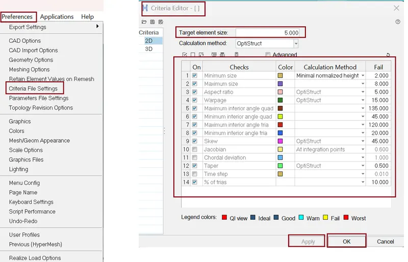
Given Quality Criteria:
Target Element Length = 5 Units
|
S.N |
Quality Criteria |
Value |
|
1. |
Aspect Ratio |
5 |
|
2. |
Skewness |
45 |
|
3. |
Warping |
15 |
|
4. |
Taper |
0.5 |
|
5. |
Min. Length |
2 Units |
|
6. |
Max. Length |
8 Units |
|
7. |
Min angle Quad |
45 |
|
8. |
Max angle Quad |
135 |
|
9. |
Min angle Tria |
20 |
|
10. |
Max angle Tria |
120 |
|
10. |
Tria % |
10 |
PROCEDURE/STEPS: -
- import cad geometry file
Here we have four sub components Hood upper body, hood inner body, two hinges and one central lock. We work on all the sub components one by one.
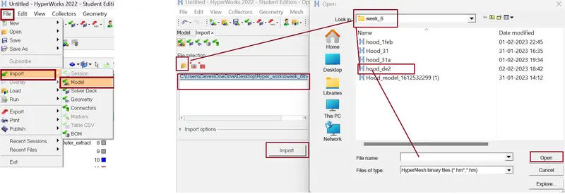
Command: File >> Import >> Model >> Locate the file directory (as per given figure) >> hit Open >> hit Import.

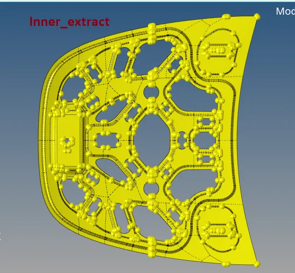
1. Hood Inner part
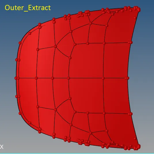
2. Hood outer part
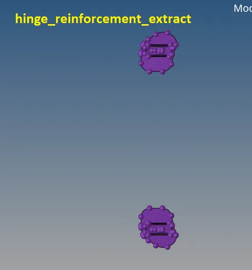
3. Hinge
4. Latch
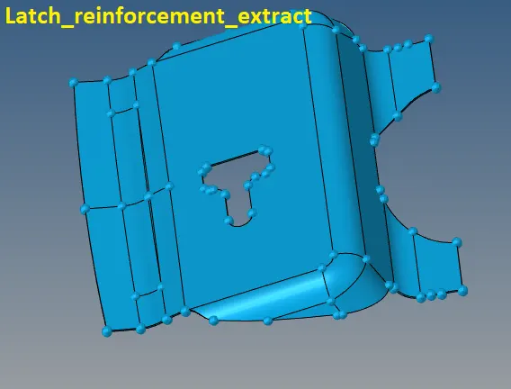
- Checking for solid surfaces:
Some times when model is import in hyper mesh then model is shown in "wireframe mode" we have to change the view to shaded by selecting "shaded geometry" view. And we check the model for any solid surface is present of the component, because we are working for the 2D mesh modelling for that we need to avoid the 3D solid surfaces.
delete the solid surfaces if there is any and then proceed for the geometry clean-up, for deleting the solid surface we have to select the delete tool and change the option to "solid" in which it only select the solid surface if available and delete.

- Extracting Mid surface
we use "auto mid surface" Option from "mid surfaces" to extract mid Surface.
Create Mid surface for only one component at a time.

Command: Geom >> midsurface >> extraction option >> select option as per figure below >> select surface >> hit extract.
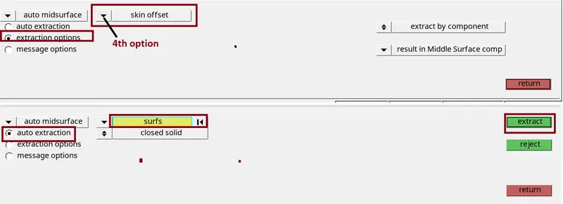
and we get mid surafce
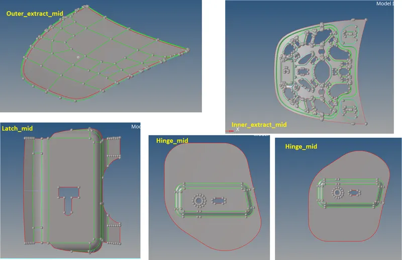
- Geometry clean-up.
- very first we change the geometry colour Mode Auto ---->>> Topo for better visibility.
-
Now we do the geometry clean-up "manually" or by "AutoCleanup" option - to clear the unwanted Line in the geometry.
-
To clean the Geometry of the Components manually we use the “ Quick edit panel” by pressing F11 and using some of the tool shown below.

- The toggle edge tool is used to suppress unwanted line.
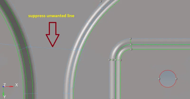
- For suppressing the line we use Toggle edge Command left click for suppressing the line and right click for generate line for dotted blue line.
- Quality Criteria setting:
Now our next objective is to do Meshing on the Component. Before meshing we need to set quality criteria.
Command for setting Quality Criteria: Preference >> Criteria file setting >> Edit the card as per figure below >> hit Apply >> ok.
2D Meshing:
Now the time to start meshing for this we use....
Command: 2D >> automesh >> edit the tab as per figure below >> select the surface >> hit mesh >> hit middle mouse click. We can also access this tab by pressing F12 key.

- The element size is changed to 5 and the mesh type is chosen as mixed and the surface to mesh is selected. After meshing some tria element is formed it can be removed by either increasing or decreasing the number of nodes under normal circumstances when the surface doesn't have extreme curves.
- created mesh is refined by using Remesh the element, rebuild the Mesh or Smooth the mesh. It is ensured that there are no rotating quads. Also, trias are kept as low as possible.
Things need to be ensured while meshing
- Avoid back-to-back trias.
- Avoid opposite trias.
- Avoid trias element at the edges.
- To fix Elements quality Criteria and trias are removed by using Tool >> edit element, >> split, >> replace, >> elem clean up.
Best way to fix Quality By using Command: 2D >> quality index >> element optimize >> left click on element which are neighbour of quality failing element >> and quality is fix. Here we all option (figure below ) to fix quality.

- The 'drag tria element' is used to move the tria elements in the mesh, two opposite trias can be moved together so that they form a quad element.
- The 'place nodes' tool is used to move the nodes of the element so that their shape can be changed or slight adjustments can be made.
- The 'split quad element' tool is used to split a quad into two trias, this is useful because the trias can be used to form quads in other places.
- The 'combine tria elements' tool is used to combine two adjacent tria elements, but this can also be achieved by using the 'drag tria element'.
- Mesh results:
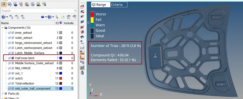
1.) Inner extract:
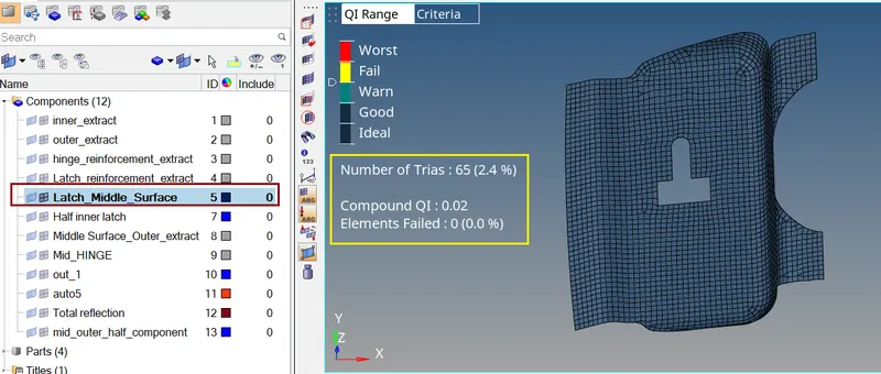
2.) Latch
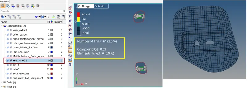
3.) Hinge
4.) Outer extract:
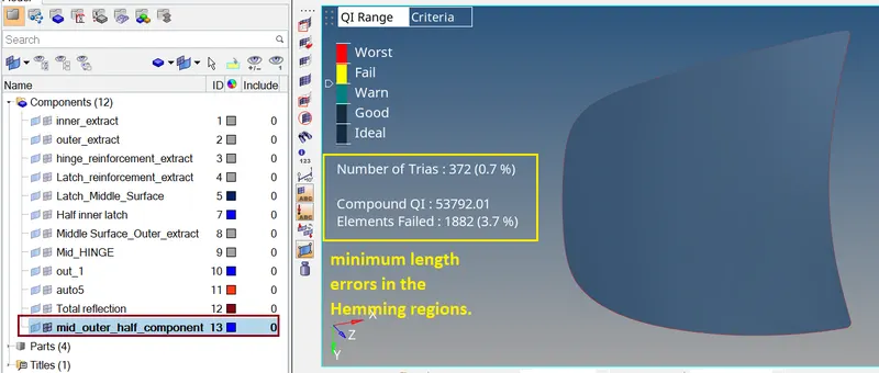
- Thickness assignment:
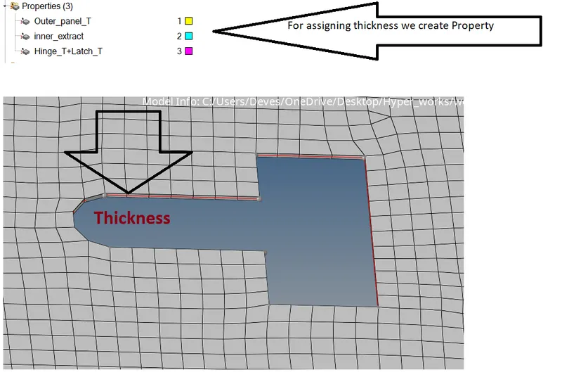
CONCLUSION:
Here we done Geometry clean-up, mid-surface extraction, and 2D meshing of the given hood model. And all the elements pass the quality criteria. All the features in the model are captured properly with good mesh flow.
Learning outcome: -
- How to clean up the geometry of given components.
- How to Extract Mid – Surface.
- Some basic Command like – edit element, split, replace, element clean up, reflect, Quality index, mask- unmask etc.
- Basics of Hypermesh Software tools and GUI.
*****************************************************************************************************************************************************************************************************************************************************************************END
Thanks & regards,
Devesh kashyap