Week 12-Creation of 1D Connectors Challenge
AIM: - To mesh the given Assemblies and create 1D connectors at desired locations using Hyper mesh.
OBJECTIVE: -
following connections have to be realized in each respective component
|
Seam-Quad (angled +capped +L) |
|
Quad elements |
|
Spot weld with 3 Layers and 5 mm Diameter |
|
Hexa (Adhesive) |
|
Bolt Connector |
|
Bolt Connector |
|
Spot-weld with Rigid Elements |
|
Spot-weld with Spring Elements |
Given Quality criteria:
Target Element size - 5 Units
|
S.N |
Quality Criteria |
Value |
|
1. |
Aspect Ratio |
5 |
|
2. |
Skewness |
45 |
|
3. |
Warping |
15 |
|
4. |
Taper |
0.5 |
|
5. |
Min. Length |
2 Units |
|
6. |
Max. Length |
8 Units |
|
7. |
Min angle Quad |
45 |
|
8. |
Max angle Quad |
135 |
|
9. |
Min angle Tria |
30 |
|
10. |
Max angle Tria |
110 |
|
11. |
Tria % |
15 |
PROCEDURE/STEPS: -
- Importing the “.hm” file
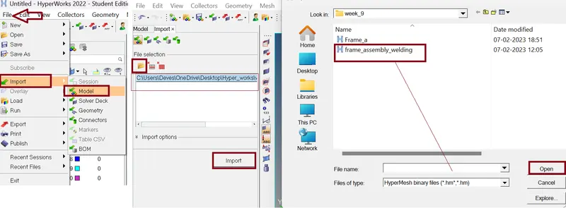
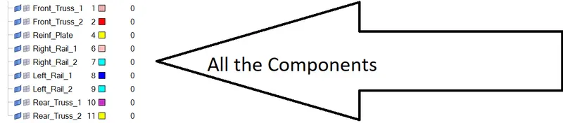
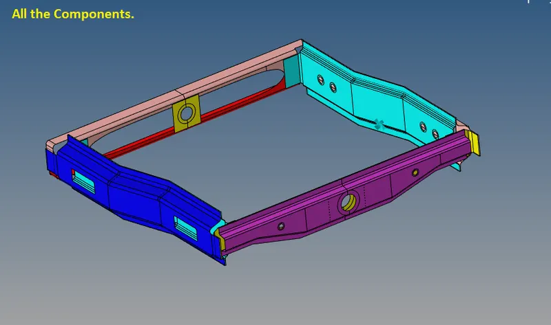
Here we have .hm file. In this file we have several components.
Command: File >> Import >> Model >> Locate the file directory (as per given figure) >> hit Open >> hit Import.
- Geometry clean-up.
- very first we change the geometry colour Mode Auto ---->>> Topo for better visibility.
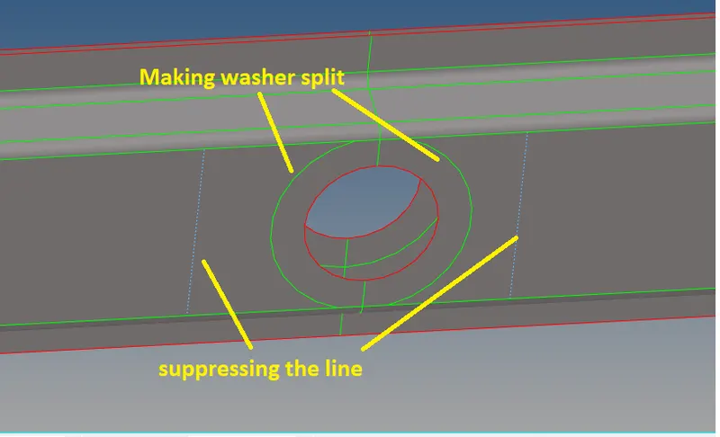
- Now we do the geometry clean-up "manually" or by "AutoCleanup" option - to clear the unwanted Line in the geometry.
- To clean the Geometry of the Components manually we use the “ Quick edit panel” by pressing F11 and using some of the tool shown below.
- For suppressing the line we use Toggle edge Command left click for suppressing the line and right click for generate line for dotted blue line.

- Quality Criteria setting:
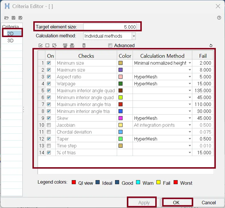
Now our next objective is to do Meshing on the Component. Before meshing we need to set quality criteria.
Command for setting Quality Criteria: Preference >> Criteria file setting >> Edit the card as per figure below >> hit Apply >> ok.
- 2D Meshing /surface Meshing: -
Each individual component is separated and meshed separately.
Command: 2D >> automesh >> edit the tab as per figure below >> select the surface >> hit mesh >> hit middle mouse click. We can also access this tab by pressing F12 key.

It is best practice to achieve a perfect mesh without quality errors the comp is sectioned into different surfaces using surf trim option and meshed separately.
Things need to be ensured while meshing
- Avoid back-to-back trias.
- Avoid opposite trias.
- Avoid trias element at the edges.
- To fix Elements quality Criteria and trias are removed by using Tool >> edit element, >> split, >> replace, >> elem clean up.
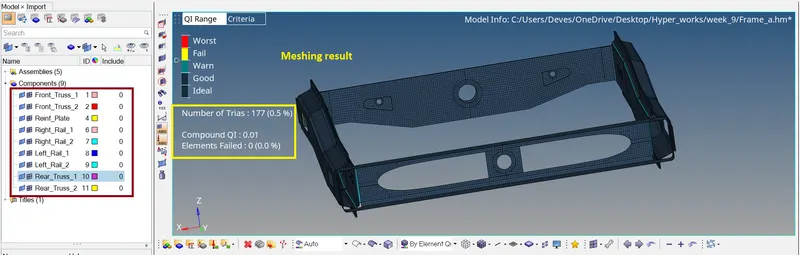
Mesh results:
Connections:
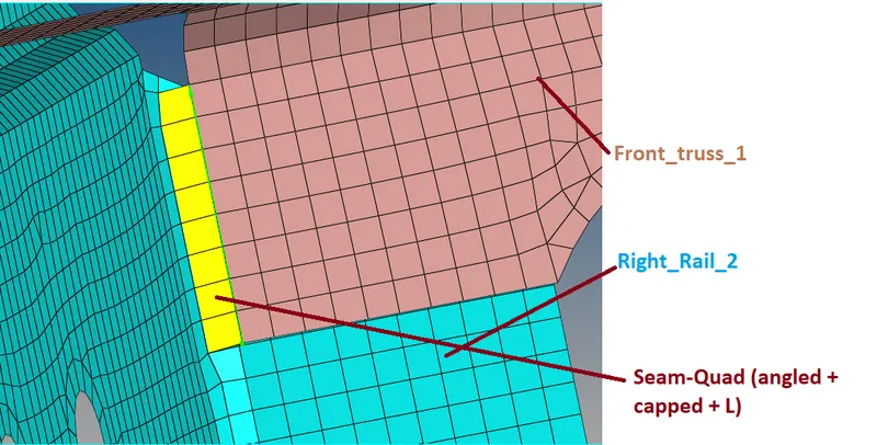
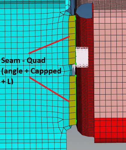
1.) Right_Rail_2 & Front_truss_1
Connection Type :- Seam-Quad (angled + capped + L)
Command : 2D >> Connectors >> Seam >> Select nodes (by path) over one of the Component >> edit the card as figure below >> hit create.

The weld angle can be altered but an angle of 60 or 45 is widely preferred in industry based on the alignment of the two components.
The spacing is set as 5mm - Spacing defines the distance between the two adjacent weld elements.
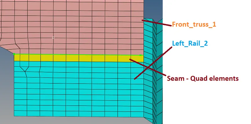
2.) Left_Rail_2 & Front_truss_1
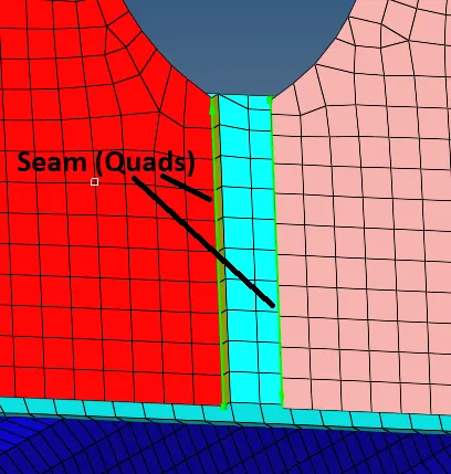
Connection Type :- Seam - Quad elements
Command : 2D >> Connectors >> Seam >> Select nodes (by path) over one of the Component >> edit the card as figure below >> hit create.

Here we just change the weld - as quad and the spacing (distance between the two adjacent weld elements) is kept as 5mm
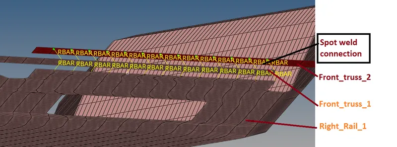
3.) Front_truss_2 , Front_truss_1 & Right_Rail_1:
Connection type :- Spot weld with 2 layers and 5mm Diameter.
Command : 2D >> Connectors >> Spot >> Select nodes (by path) over one of the Component >> select two Component at a time >> edit the card as figure below >> hit create.

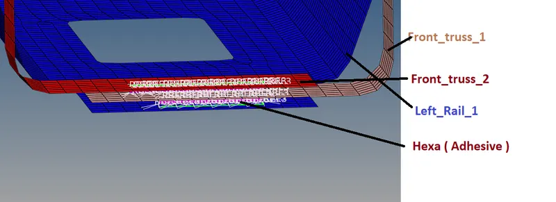
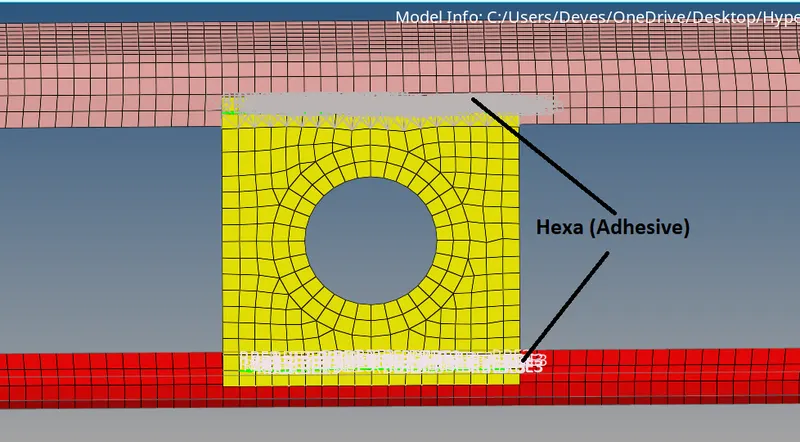
4.) Front_truss_2, Front_truss_1 & Left_Rail_1 :
Connection type : Hexa (Adhesive)
Command : 2D >> Connectors >> Seam >> Select nodes (by path) over one of the Component >> edit the card as figure below >> hit create.

Here we Select the two components at a time and keep the imprint check on. weld type is set as hexa (adhesive) under the weld type category. The strips and coats of the weld can be altered. In this case, the strip is set as 2 and a single coating is specified
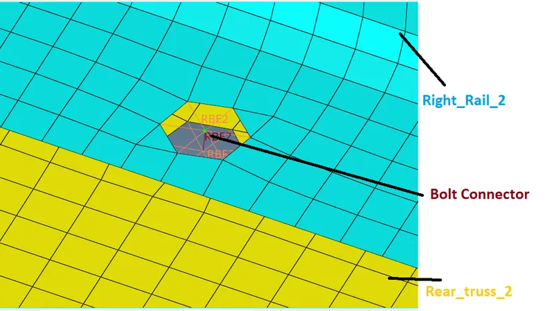
5.) Rear_truss_2 & Right_Rail_2:
Connection type: Bolt Connector
Command : 2D >> Connectors >> bolt >> Select nodes over one of the Component >> edit the card as figure below >> hit create.

Specify the location of the bolt by selecting the single nodes at a certain distance.
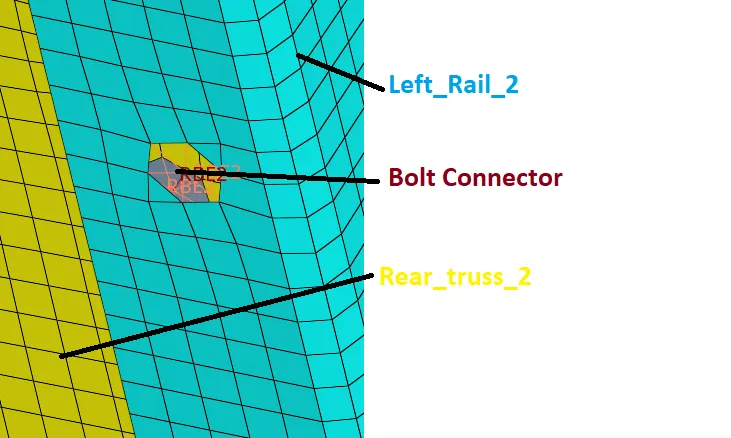
6.) Rear_truss_2 & Left_Rail_2:
Connection type : Bolt Connector
Similarly, as previous we can make bolt connection
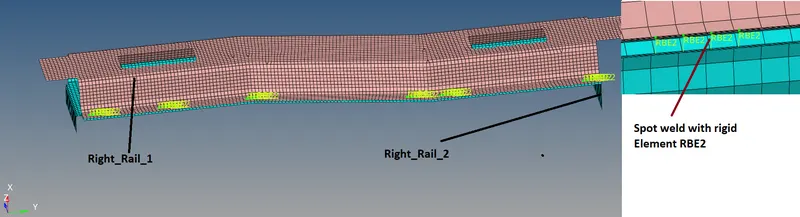
7.) Right_Rail_1 & Right_rail_2:
Connection type : Spot weld with Rigid Elements
Command : 2D >> Connectors >> Spot >> Select nodes (by path) over one of the Component >> select two Component at a time >> edit the card as figure below >> hit create.

As similar to previous spot weld creation, this spot weld is created using rigids instead of weld
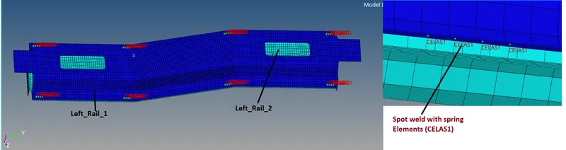
8.) Left_Rail_1 & Left_Rail_2:
Connection type : Spot weld with Spring Elements
Command : 2D >> Connectors >> Spot >> Select nodes (by path) over one of the Component >> select two Component at a time >> edit the card as figure below >> hit create.

here the spot element type is set as spring instead of rigid or weld
9.) other components
shell component with the hole, an adhesive connection is made. Adhesives are RBE3 elements that distribute load applied to its master node. Unlike RBE2 elements, RBE3's do not impart infinite stiffness to the component.
Here we make connection in some different portion, where we feel connection is required.
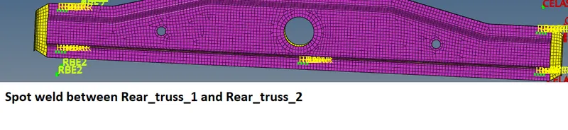
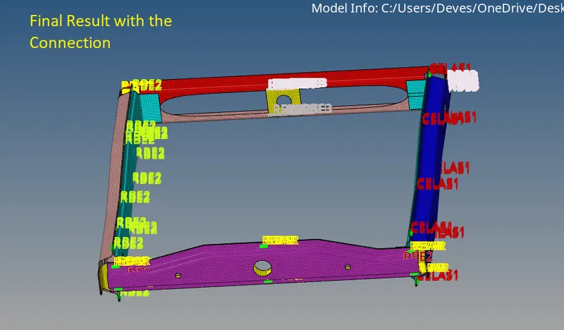
Final components look like...
CONCLUSION:
Here all components have been meshed and required connections have been defined successfully and also realized Successfully.
Learning outcome: -
- Here we learned about how to do 1D connections at various locations.
- How to successfully realize the Connection.
- Also learned a little when to use which type of connector and what all factors decide the selection of connector type.
- learned about all the type of connectors we have in Hyper Mesh.
*****************************************************************************************************************************************************************************************************************************************************************************************END
Thanks & regards,
Devesh kashyap