Week 7-Long Piston With Cam
AIM: - To perform a transient analysis on a piston and cam mechanism model using Ansys workbench.
OBJECTIVE:
To perform a transient analysis on a piston and cam mechanism model with following setup CASES
- CASE:1 To run the analysis with Frictionless contact.
- CASE:2 To run the analysis with Frictional contact (coefficient of friction is 0.1).
- CASE:3 To run the analysis with Frictional Contact (coefficient of friction is 0.2).
THEORY:
- A cam-follower is a mechanical component used in various machines and mechanisms to convert rotary motion into linear motion. It typically consists of a cam, which is a rotating component with an irregular shape, and a follower, which is a component that rides along the cam's surface. As the cam rotates, the follower is forced to move up and down, or side to side, depending on the shape of the cam profile.
- Cam-followers are used in a wide range of applications, including engines, pumps, and industrial machinery. They are particularly useful in situations where precise and repeatable linear motion is required, such as in automotive engines, where cam-followers are used to open and close engine valves.
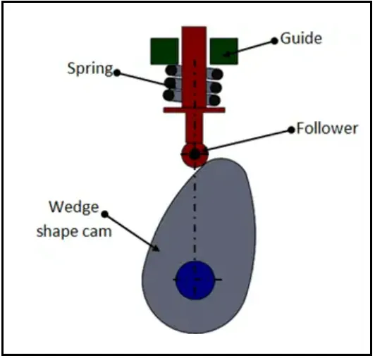
- Cam-followers can be designed in a variety of shapes and sizes, depending on the specific application. They can be made from a variety of materials, including metal, plastic, and ceramics, and can be lubricated or dry-running, depending on the application requirements.
- Overall, cam-followers are an essential component in many mechanical systems, providing efficient and precise linear motion that is critical for the proper functioning of many machines and mechanisms.
Transient Analysis
- Transient analysis is a type of analysis used in various fields, such as physics, electrical engineering, and mechanical engineering, to study the behavior of a system over time. It is used to analyze the system's response to changes in inputs or initial conditions.
- In mechanical engineering, transient analysis is used to study the behaviour of physical systems, such as a vibrating beam or a rotating shaft. Transient analysis can be used to determine how the system responds to changes in inputs or initial conditions, such as changes in force or velocity.
- Transient analysis involves solving differential equations that describe the system's behaviour over time. These equations can be solved using numerical methods, such as finite element analysis or finite difference analysis. The results of the analysis can be used to understand the system's behaviour, design and optimize the system, and predict how the system will respond to changes in inputs or initial conditions.
transient analysis in ANSYS Workbench is a powerful tool for simulating the behaviour of a system over time. It is widely used in engineering applications to investigate the response of a system to time-varying inputs. ANSYS Workbench provides a range of analysis tools to perform transient analysis, including explicit and implicit solvers. The transient analysis workflow in ANSYS Workbench involves defining the geometry, material properties, boundary conditions, transient analysis settings, running the simulation, and analysing the results.
ANALYSIS SETUP:
Here we will start our work Transient structural Analysis for piston and cam mechanism model in three different cases.
- CASE:1 To run the analysis with Frictionless contact.
- CASE:2 To run the analysis with Frictional contact (coefficient of friction is 0.1).
- CASE:3 To run the analysis with Frictional Contact (coefficient of friction is 0.2).
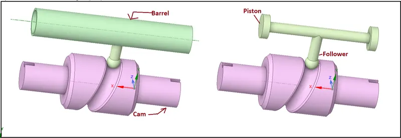
- Given Geometry
- Mesh:
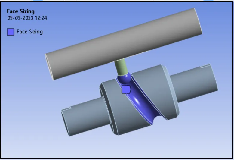
Details:
- Global Element Size: Default
- Face Sizing: 1.5 mm
- Body Sizing: 3mm
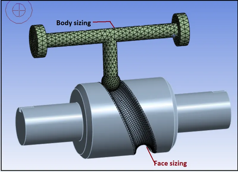
- Nodes - 15997
- Elements - 8019
Material {Structural Steel}:
- Density: 7850 Kg/m3
- Young’s Modulus: 2 E+05 MPa
- Poisson’s Ratio: 0.3
- Tensile Yield Strength: 250 MPa
- Compressive Yield Strength: 250 MPa
- Tensile Ultimate Strength: 460 MPa
Initial steps
- Import model in Transient Structural in Geometry section.
- Then go to Mechanical model section.
- Check or Rename the Parts of the setup as barrel, BARREL_CAM and CAM_FOLLOWER.
Connections:
Contact: 1st one
- Contact Body = CAM_FOLLOWER
- Target Body = barrel
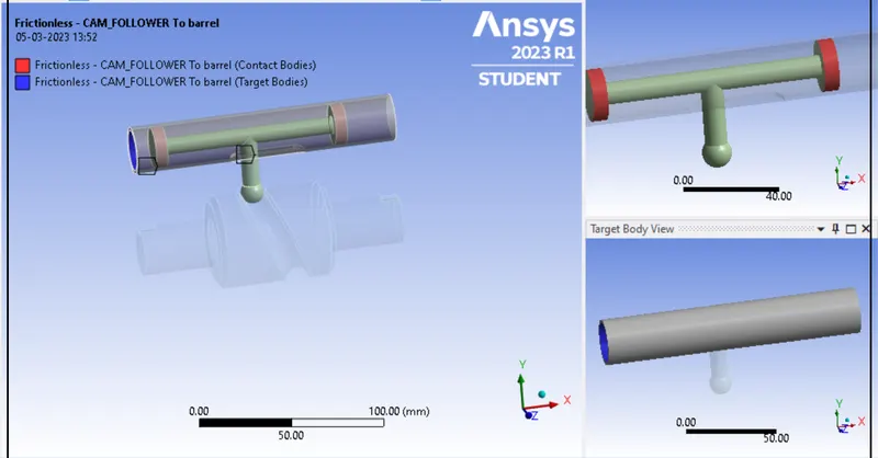
Contact: 2nd one
- Contact Body = CAM_FOLLOWER
- Target Body = BARREL_CAM
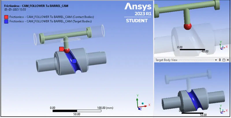
Settings we need to edit for both Contacts:
- For CASE: 1 {Type: Friction less}
- For CASE: 2 {Type: Frictional}
Friction Coefficient = 0.1
- For CASE :3{Type: Frictional}
Friction Coefficient = 0.2
Joints:
Joint: First
- Connection Type: Body-Ground
- Type: Fixed
- Body: barrel
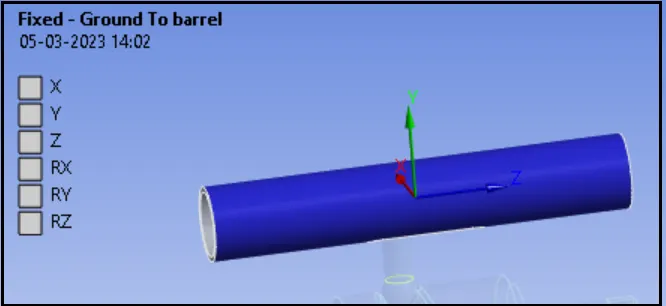
Joint: second
- Connection Type: Body-Ground
- Type: Revolute
- Body: BARREL_CAM
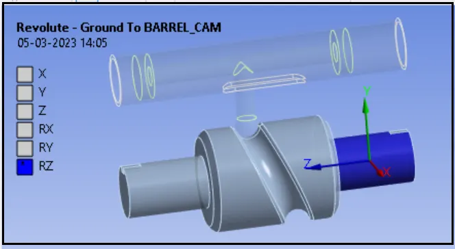
Here we need to Make sure that the Z-axis is the axis of rotation
Joint: Third
- Connection Type: Body-Ground
- Type: Translational
- Body: CAM_FOLLOWER.
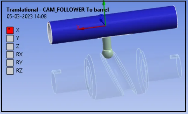
Here we need to Make sure that X-axis is the axis of translation.
Boundary Conditions settings:
Our next step is creating Boundary Conditions:
Analysis Settings:
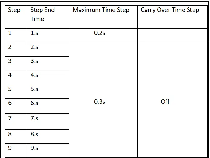
No. of Steps: 9
For 1st Step:
- Solver Type: Program Controlled
- Weak Springs: Program Controlled
- Large Deflection: ON
- Auto Time Stepping: ON
- Defined By: Time
- Initial Time Step: 0.1 s
- Minimum Time Step: 5e-2 s
- Maximum Time Step: 0.2 s
- Nonlinear Controls:
- Stabilization: Constant
- Method: Energy
- Energy Dissipation Ratio: 0.1
j.Update at each iteration: Yes
For 2nd to 9th Step:
- Solver Type Program Controlled
- Weak Springs: Program Controlled
- Large Deflection: ON
- Auto Time Stepping: ON
- Defined By: Time
- Initial Time Step: 1 s
- Minimum Time Step: 5e-2 s
- Maximum Time Step: 0.3 s
- Nonlinear Controls:
- Stabilization: Constant
- Method: Energy
- Energy Dissipation Ratio: 0.1
j. Update at each iteration: Yes
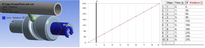
joint Rotation:
Apply Joint rotation to rotate the cam and thus the follower will follow the motion.
SOLUTION
After giving proper boundary conditions, create desired solutions for output results.
- Equivalent Stress
- Equivalent Strain
- Directional Deformation for Follower
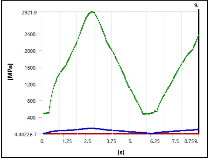
Stress Comparison for CASE:1 {Friction less}, CASE:2{Frictional contact with cof -0.1} and CASE :3{Frictional contact with cof -0.2}
- Stress in CASE:1 {Friction less}
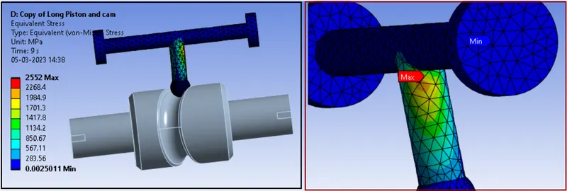
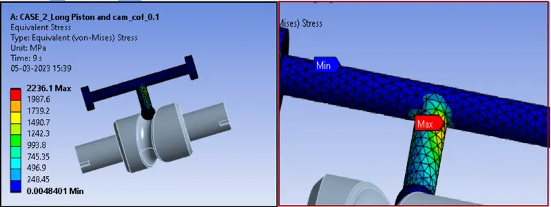
- Stress in CASE:2 {Frictional contact with cof -0.1}
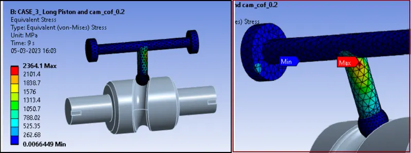
- CASE :3{Frictional contact with cof -0.2}
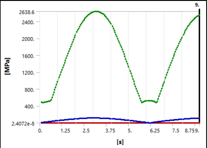
Stress plots
CASE:1{Friction less}
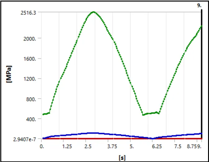
CASE:2 {Frictional contact with cof - 0.1}
CASE :3{Frictional contact with cof -0.2}
Detailed Stress Data:

Coments:
- we can see that at the time 3 to 4 s, where the cam rotates from 90 to 120-degree, stress is Maximum.
- It means, maximum bend or torque is generated between 90 to 120 degree and at the 3 to 4 s.
- we can see that stress in CASE: 1 (Friction less), is higher compared to CASE: 2 (friction coefficient = 0.1).
- Maximum stress occurring at the neck portion or at the right angle of the follower.
- In frictionless contact, follower can move along the cam without friction and fast. So, more torque will be transferred to the follower and due to easy translation, maximum stress is generation at the right angle of follower.
- But in we observe in CASE: 3, where the friction coefficient is 0.2, maximum stress is higher compared to CASE: 2. Because the increased friction, increase in stress can be observed.
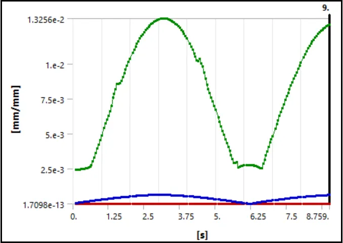
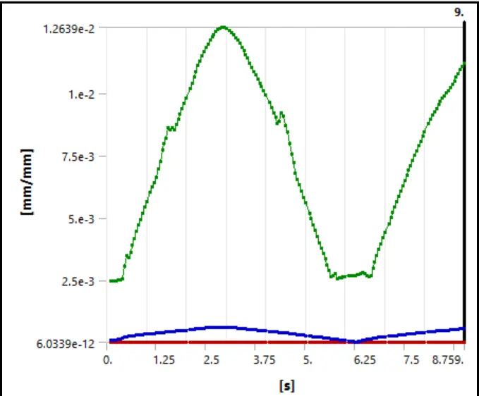
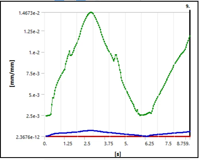
Strain Comparison for CASE:1 {Friction less}, CASE:2{Frictional contact with cof -0.1} and CASE :3{Frictional contact with cof -0.2}
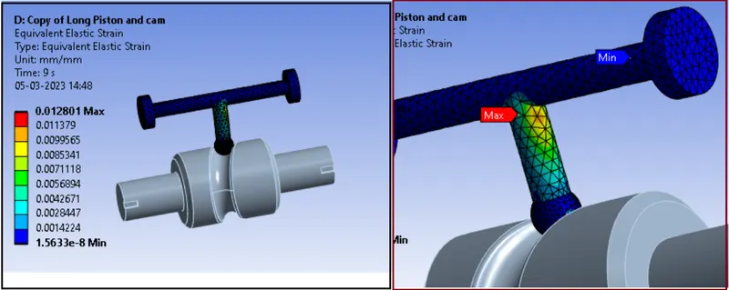
- Strain in CASE:1 {Friction less}
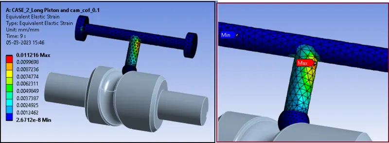
- Strain in CASE:2 {Frictional contact with cof -0.1}
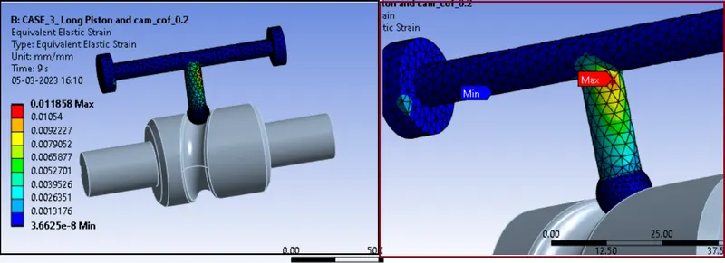
- Strain in CASE :3{Frictional contact with cof -0.2}
Strain plots
CASE:1 {Friction less}
CASE:2 {Frictional contact with cof - 0.1}
CASE :3{Frictional contact with cof -0.2}
Detailed Strain Data:

Coments
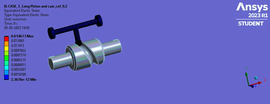
Here we observe Maximum strain in CASE:3, due to higher friction compared to other cases.
we know that from previous result maximum bending of follower is occurring between 90 to 120 degrees of the cam rotation, we can see the maximum strain is also between the 3.5 to 4 s.
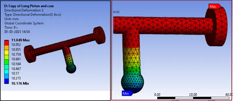
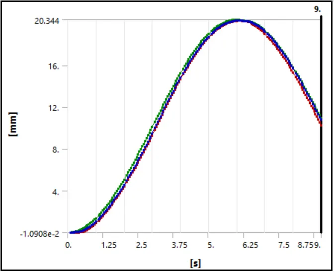
Deformation in X - direction Comparison for CASE:1 {Friction less}, CASE:2{Frictional contact with cof -0.1} and CASE :3{Frictional contact with cof -0.2}
- Deformation in CASE:1 {Friction less}
- Deformation in CASE:2 {Frictional contact with cof - 0.1}
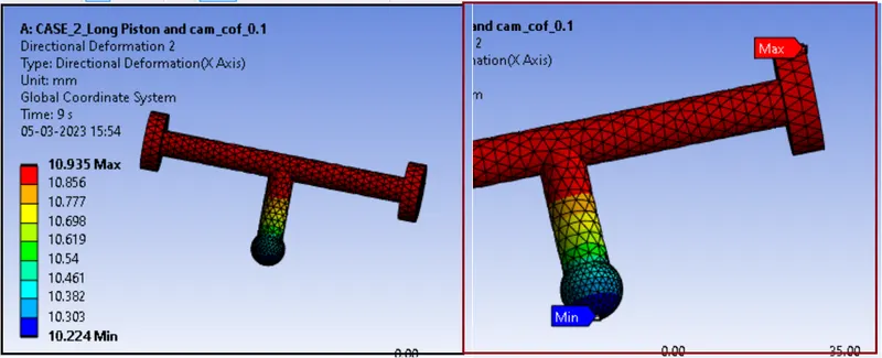
- Deformation in CASE:3 {Frictional contact with cof - 0.2}
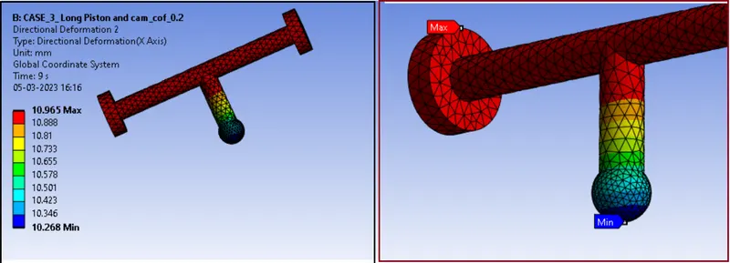
Deformation plots
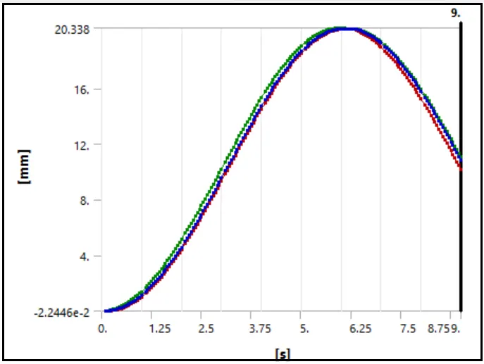
CASE:1 {Friction less}
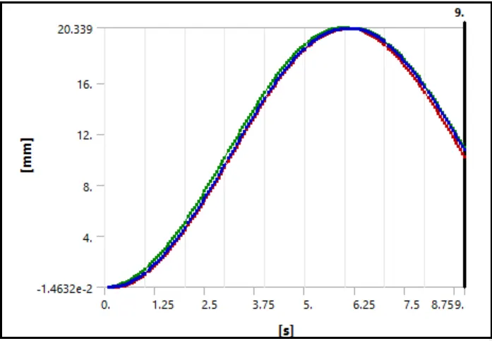
CASE:2 {Frictional contact with cof - 0.1}
CASE:3 {Frictional contact with cof - 0.2}
Detailed Deformation (X – direction) Data:
Coments:
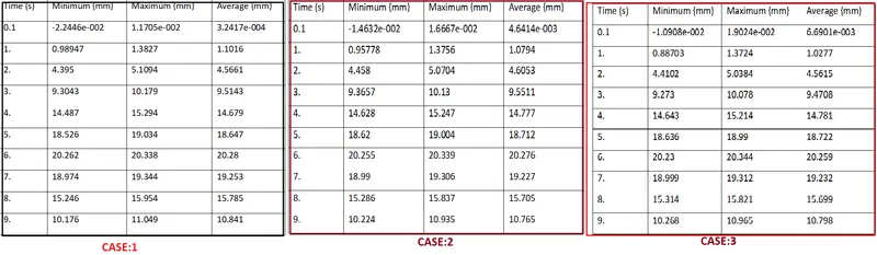
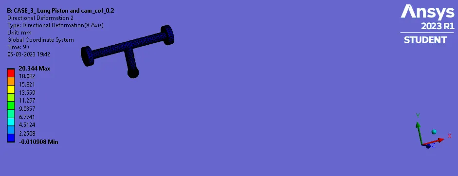
- Here we can observe the maximum deformation in X direction is approximately same in all the cases.
- The follower is translating, so we can observe the maximum deformation or displacement of the follower at the 6 s, where the cam rotates about 180 degrees.
- Also due to higher pressure and repetition of acceleration as well as deceleration, there is some deformation in Y Direction also.
Result Summary:
CONCLUSION:
- it is impossible to have complete frictionless contact between cam and follower.
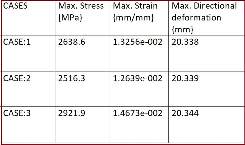
- As per results, we can observe that as the friction increases, stress and strain values and deformation due to higher pressure also increases.
- When friction is higher, pressure on the tip of the follower, where it is in contact with cam, gets deformation. It can bend or twist due to the following path of the cam.
- In a cam and follower mechanism, friction plays a significant role in determining the performance and efficiency of the system. Frictional forces act between the cam and follower components and can affect several aspects of the mechanism, such as power transmission, wear and tear, and accuracy of motion.
Here are some ways in which friction affects the performance of a cam and follower mechanism:
- Power transmission: Frictional forces between the cam and follower can cause energy loss and reduce the efficiency of power transmission. The greater the frictional forces, the more power is required to maintain the motion of the follower.
- Wear and tear: Friction can cause wear and tear on the cam and follower components, which can lead to reduced lifespan and performance of the mechanism. This is especially true when the cam and follower are made of materials with different coefficients of friction, which can lead to uneven wear.
- Accuracy of motion: Frictional forces can also affect the accuracy of motion of the follower, especially in high-speed applications. If the friction is too high, it can cause the follower to stick or jump, leading to inaccurate motion and potentially damaging the mechanism.
To reduce the negative effects of friction in cam and follower mechanisms, designers often use lubrication or specialized coatings to reduce the coefficient of friction between the cam and follower components. They may also use materials with similar coefficients of friction to reduce wear and ensure smooth operation.
-----------------------------------------------------------------------------------------------------------------------------------------------------------------------------------------------------
ANNIMATION
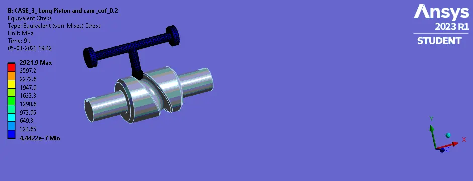
CASE:3 {Frictional contact with cof - 0.2}
Stress
Strain
Directional Deformation (X – direction)
Velocity
Here Due to large size of the Ansys file (2.19GB) , I have attached a link for the Ansys .wbpz file in below "Model Browse" area.
Kindly find attached link via word document.
*********************************************************************************************************************************************END
Thanks & regards,
Devesh kashyap