Week 3 Sheet metal Bending challenge
OBJECTIVE:
To Perform static structural analysis/ Simulation for sheet metal bending operation.
- CASE:1 {Material for sheet - Aluminium Alloy 1199}
- CASE:2 {Material for sheet - Copper Alloy NL}
- CASE:3 {Material for sheet - Magnesium Alloy NL}
- CASE:4 {Aluminium Alloy with Friction Coefficient 0.19}
- CASE:5 {Aluminium Alloy with Mesh Refinement}
THEORY:
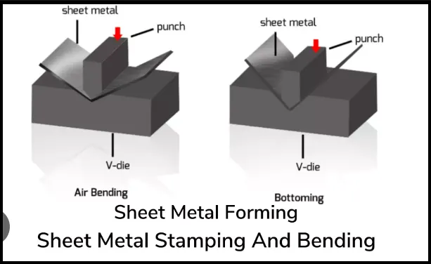
Sheet metal bending is a manufacturing process that involves shaping a sheet of metal into a desired form or angle by applying force to it using a bending tool or machine. The process of bending sheet metal is commonly used in the fabrication of a wide variety of products such as enclosures, brackets, frames, and other metal parts.
Sheet metal bending is an important process in the manufacturing of metal parts, and it requires skill and precision to produce high-quality, accurately bent parts. The design of the part, the type of metal being used, and the bending method all play a role in the final product.
Sheet metal bending analysis is a process used to determine the stresses and strains that occur during the bending process of a sheet metal part. This analysis helps engineers to optimize the bending process and ensure that the part will meet the required specifications.
The analysis typically involves the following steps:
- Material characterization: The material properties of the sheet metal being used, such as its elastic modulus and yield strength, are determined through testing or provided by the manufacturer.
- Bending simulation: Using computer-aided design (CAD) software, a 3D model of the part is created and simulated to determine the amount of force required to bend the sheet metal to the desired shape. This simulation can also show any areas of the part that may be prone to wrinkling or cracking during the bending process.
- Stress analysis: Finite element analysis (FEA) is used to calculate the stresses and strains that occur in the sheet metal during bending. This analysis takes into account the material properties, the applied force, and the geometry of the part.
- Optimization: Based on the results of the stress analysis, the bending process can be optimized by adjusting parameters such as the bend angle, the radius of the bend, and the applied force.
By using sheet metal bending analysis, engineers can ensure that parts are designed and manufactured to meet the required specifications, while minimizing the risk of defects such as wrinkling or cracking. This analysis also helps to reduce material waste and production costs by optimizing the bending process.
ANALYSIS SETUP:
Here we categorized Structural analysis of sheet metal bending process will be in 5 different cases with some changes of Material or Parameters are as given below:
- CASE:1 {Material for sheet - Aluminium Alloy 1199}
- CASE:2 {Material for sheet - Copper Alloy NL}
- CASE:3 {Material for sheet - Magnesium Alloy NL}
- CASE:4 {Aluminium Alloy with Friction Coefficient 0.19}
- CASE:5 {Aluminium Alloy with Mesh Refinement}
We will use different Material (CASE:1- CASE:3), Different coefficient of friction between the surfaces (CASE: 4) and different Mesh size only for sheet (CASE:5). and find out the Equivalent stress, Equivalent Elastic strain, Total Deformation in Y-axis.
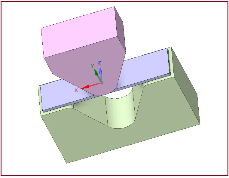
- Given Geometry:
- Mesh:
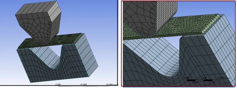
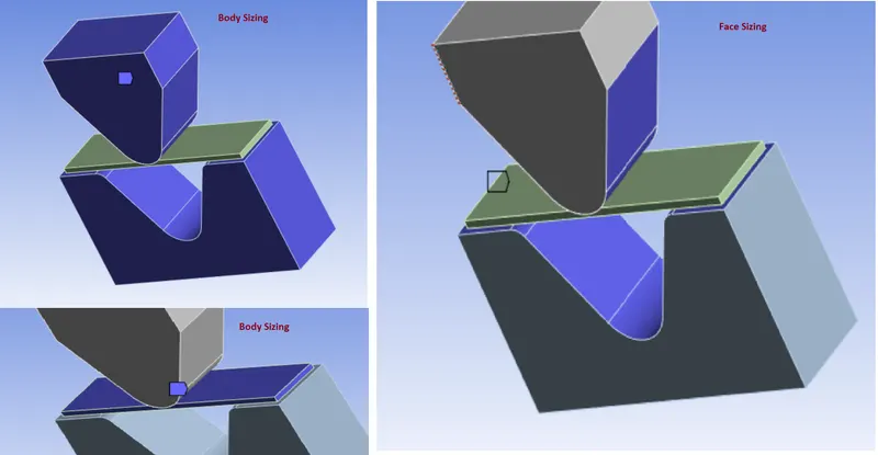
Mesh Details for CASE:5 only.
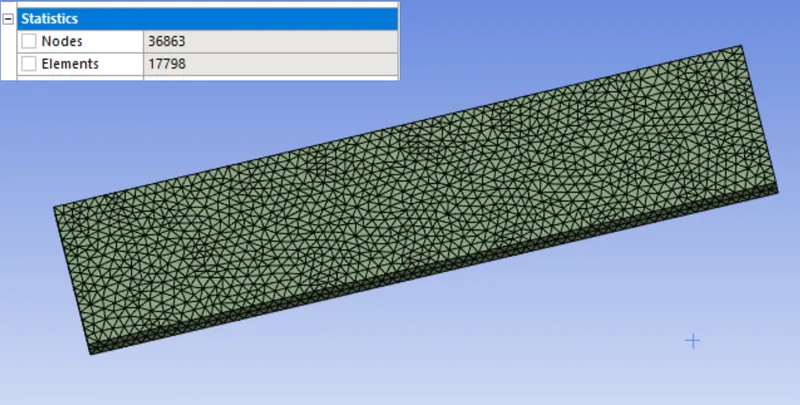
Element size - 0.60mm
Mesh Details for CASE:1, CASE:2, CASE:3 & CASE: 4
- Body Sizing: 4 mm (For Punch & Die)
- Body Sizing: 1 mm (For Sheet)
- Face Sizing: 1 mm (For All Contact Faces)
- Patch Conforming Method: Tetrahedrons
- No. of Nodes: 17859
- No. of Elements: 6229
Material:
CASE:1 {Material - Aluminium Alloy 1199}
- Density: 2770 Kg/m3
- Young’s Modulus: 62000 MPa
- Poisson’s Ratio: 0.33
- Yield Strength: 140 MPa
- Tangent Modulus: 209.46 MPa
CASE:2 {Material - Copper Alloy NL}
- Density: 8300 Kg/m3
- Young’s Modulus: 1.1 E+05 MPa
- Poisson’s Ratio: 0.34
- Yield Strength: 280 MPa
- Tangent Modulus: 1150 MPa
CASE:3 {Material - Magnesium Alloy NL}
- Density: 1800 Kg/m3
- Young’s Modulus: 45000 MPa
- Poisson’s Ratio: 0.35
- Yield Strength: 193 MPa
- Tangent Modulus: 920 MPa
CASE:4 & CASE:5 {Material - Aluminium Alloy}
- Density: 2770 Kg/m3
- Young’s Modulus: 71000 MPa
- Poisson’s Ratio: 0.33
- Tensile Yield Strength: 280 MPa
- Tensile Ultimate Strength: 310 MPa
Initial Steps
- Very first we Import the model in Static Structural named as Skill_lync_Al_Sheet_Bending.x_t in Geometry section.
- Then go to Mechanical model section.
- Check or Rename the Parts of the setup as punch , sheet and Die as shown in above geometry image.
- Connections:
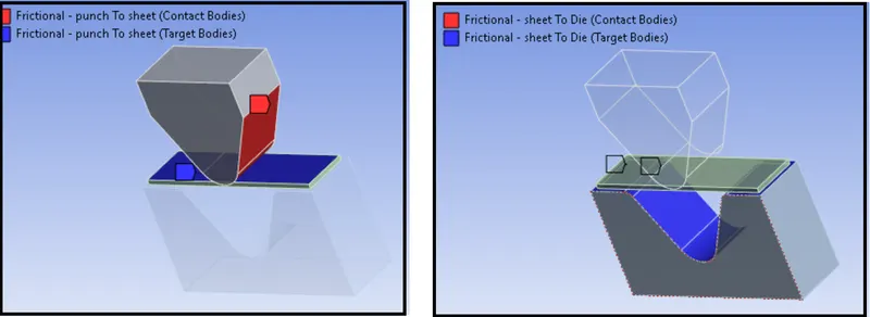
Very first we need to Delete automatically created contacts and create new contacts as given below:
Contact: 1st one
- Contact Body = Punch
- Target Body = Sheet
Contact: 2nd one
- Contact Body = Sheet
- Target Body = Die
Settings we need to edit for Both the Contacts.
- Type: Frictional
- Friction Coefficient: 0.1
- Behavior: Auto Asymmetric
- Formulation: Augmented Lagrange
- Normal Stiffness Factor: 0.1
- Interface Treatment: Add Offset, Ramped Effects
- Boundary Conditions settings:
Our next step is creating Boundary Conditions:
Analysis Settings:
- No.of Steps: 10
- Auto Time Stepping: Program Controlled
- Solver Type: Direct
- Large Deflection: ON
- Non-Linear Controls: Stabilization = Constant
- Method = Energy
- Energy Dissipation Ratio = 0.1
Here we want to bend the Sheet with help of Punch in the Die.
So, we have to give different displacements in order to move or restrict the movement in some direction of parts.
Displacement: 1st one
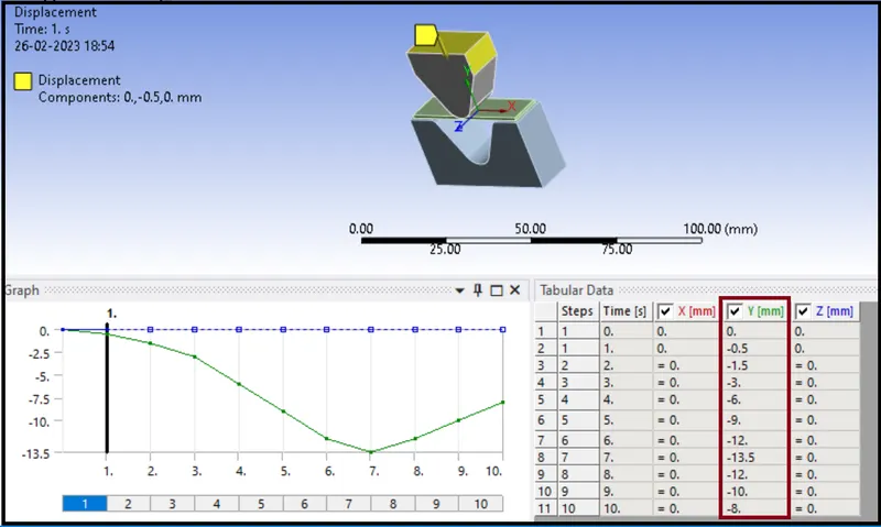
This movement is for punch in Y-Direction only.
Displacement: 2nd one
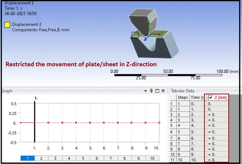
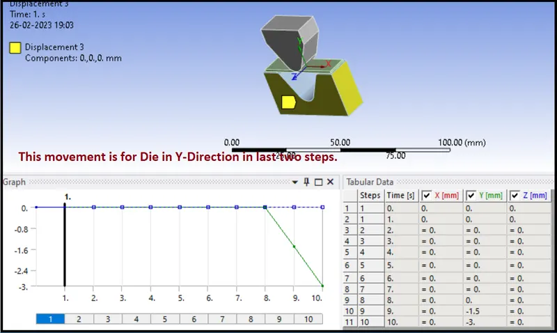
Displacement: 3rd one
SOLUTION
After giving proper boundary conditions, create desired solutions for output results. Create Solutions for Equivalent (Von Mises) Stress, Equivalent (Von Mises) Strain and Total Deformation and Directional Deformation in Y-axis.
Now we observe results with comparison.
CASE:1 {Material for sheet - Aluminium Alloy 1199}
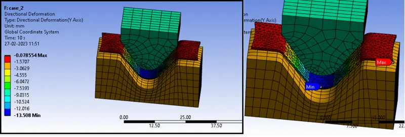
CASE:2 {Material for sheet - Copper Alloy NL}
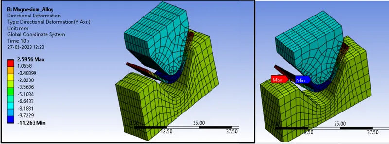
CASE:3 {Material for sheet - Magnesium Alloy NL}
Results for CASE: 1, CASE: 2 and CASE:3 are as given below:
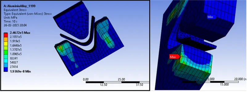
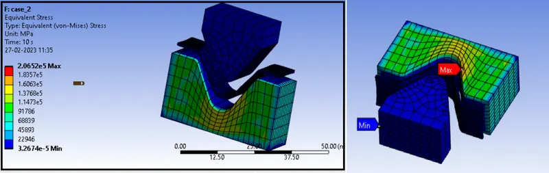
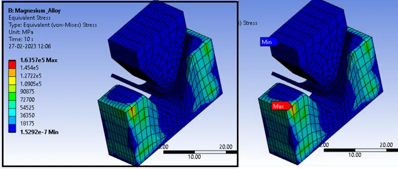
- Stress
{Aluminium Alloy 1199}
{Copper Alloy NL}
{Magnesium Alloy NL}
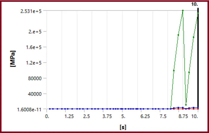
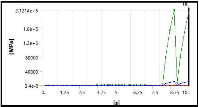
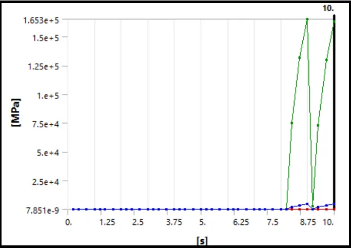
- Stress Plot
{Aluminium Alloy 1199}
{Copper Alloy NL}
{Magnesium Alloy NL}
- Detail Stress {Aluminium Alloy 1199, Copper Alloy NL and Magnesium Alloy NL} Results:
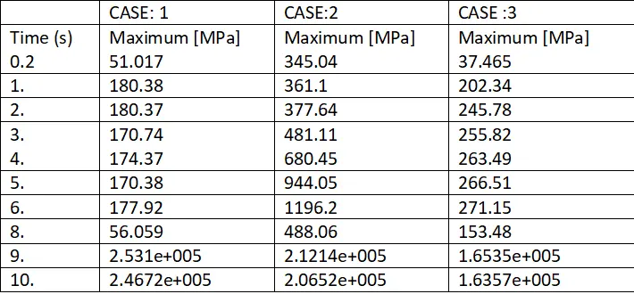
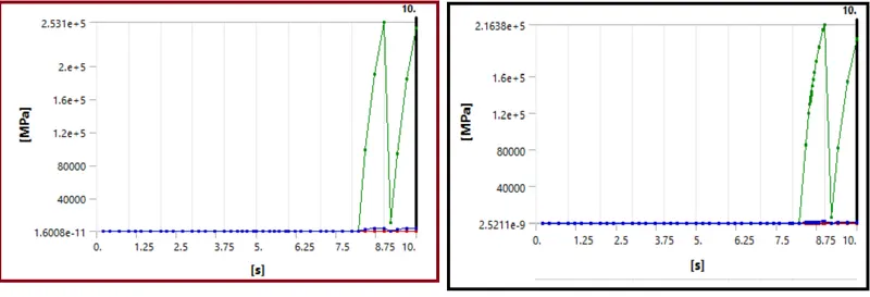
- From this graph and plots, we can see the maximum stress develops in the Die.
- Also we can see that these stresses are inducing due to removal of load in the Punch in the last two steps of plot.
- Due to Non-Linear material the stress in the sheet is lower compared to Die.
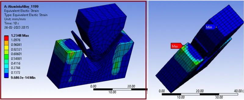
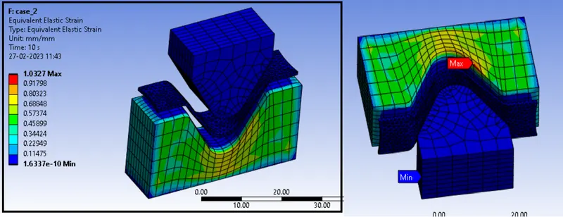
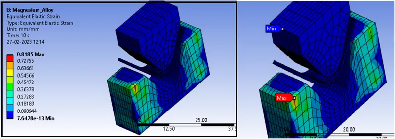
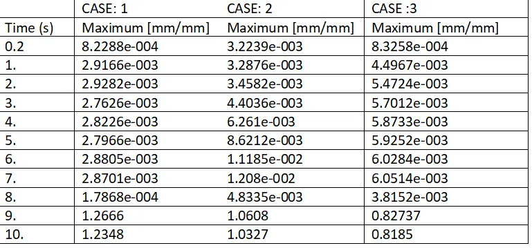
- Strain
{Aluminium Alloy 1199}
{Copper Alloy NL}
{Magnesium Alloy NL}
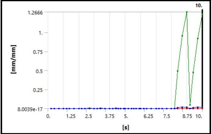
- Strain Plots
{Aluminium Alloy 1199}
{Copper Alloy NL}
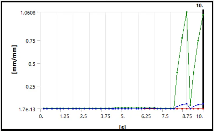
{Magnesium Alloy NL}
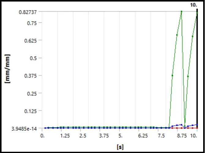
- Detail Strain {Aluminium Alloy 1199, Copper Alloy NL and Magnesium Alloy NL} Results:
- Deformation
{Aluminium Alloy 1199}
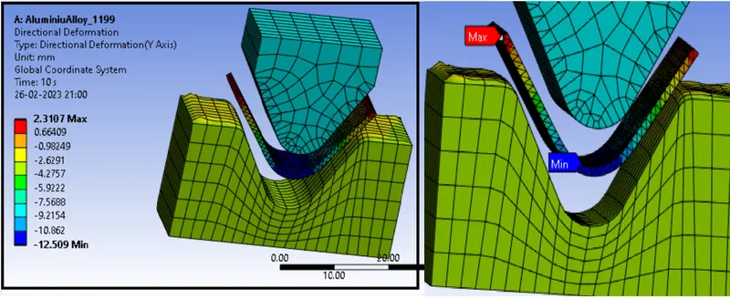
{Copper Alloy NL}
{Magnesium Alloy NL}
- Deformation Plots:
{Aluminium Alloy 1199}
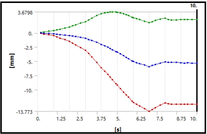
{Copper Alloy NL}
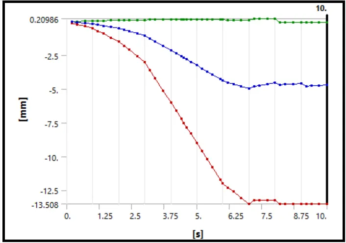
{Magnesium Alloy NL}
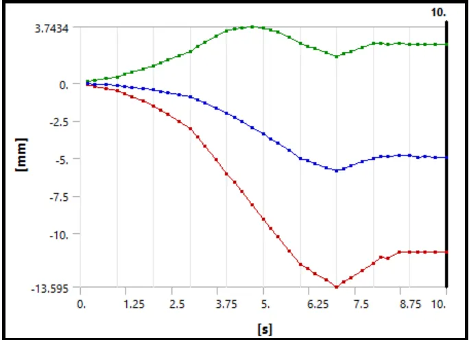
- Detail deformation {Aluminium Alloy 1199, Copper Alloy NL and Magnesium Alloy NL} Results:
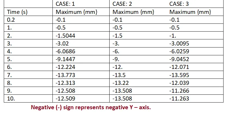
Maximum deformation is observed at the end portion of the sheet, which is due to large Plastic displacement.
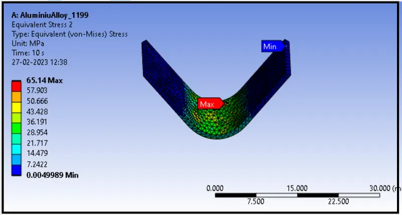
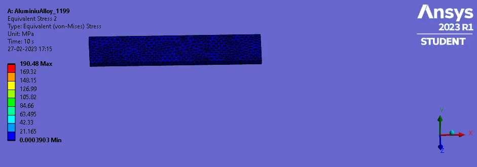
- Stress in the Sheet
{Aluminium Alloy 1199}
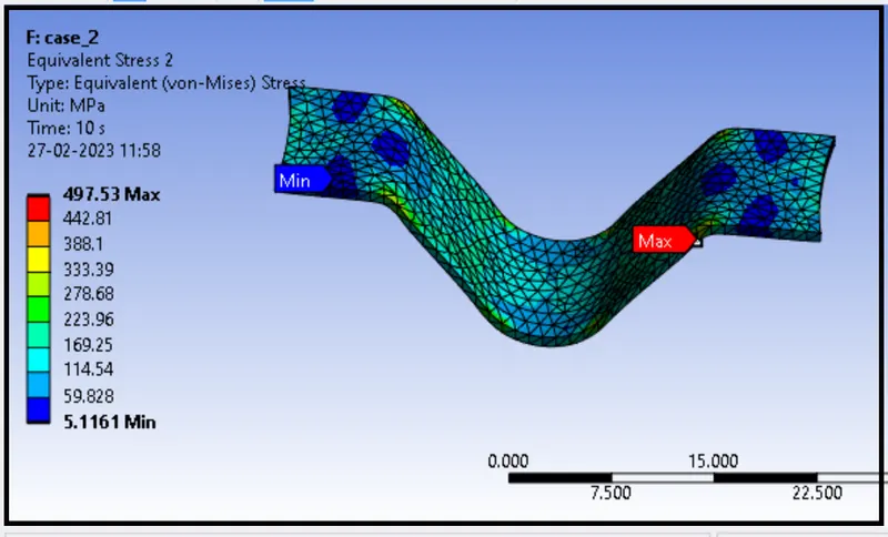
{Copper Alloy NL}
{Magnesium Alloy NL}
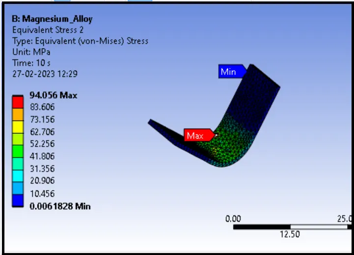
- Stress plots for sheet/plates
{Aluminium Alloy 1199}
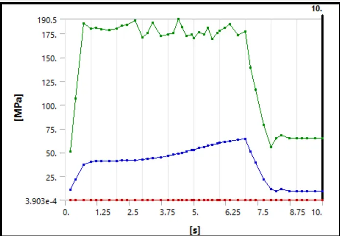
{Copper Alloy NL}
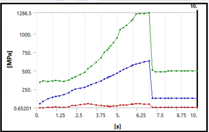
{Magnesium Alloy NL}
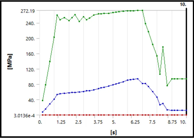
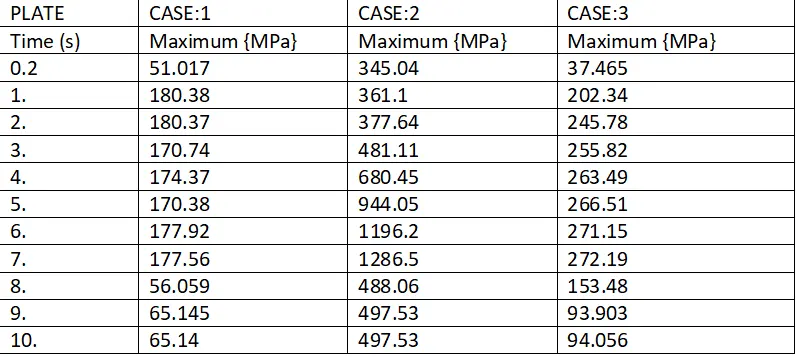
- Detail Stress {Aluminium Alloy 1199, Copper Alloy NL and Magnesium Alloy NL} Results for sheet:
*****************************************************************************************************************************
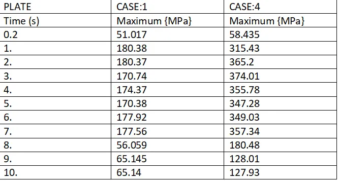
Comparison of CASE:1 & CASE:4
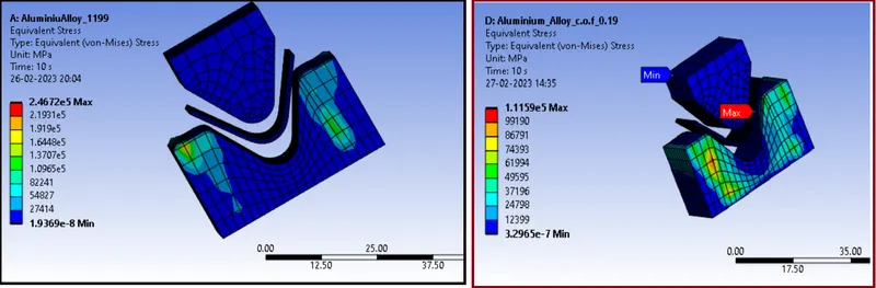
Now we will see the results and comparison of Aluminium Alloy 1199 and Aluminium Alloy (with Coefficient of friction = 0.19)
- Stress
- Stress Plots
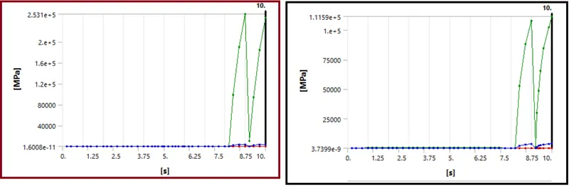
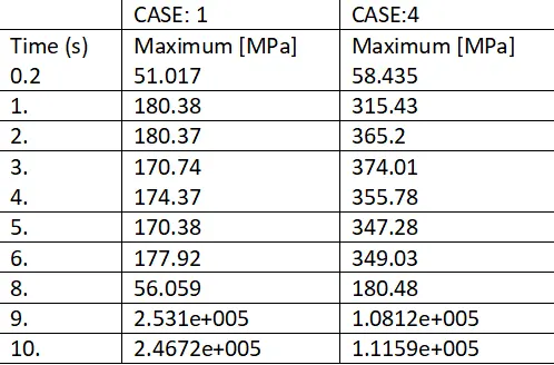
- Detail Stress {CASE:1 & CASE:4} Results:
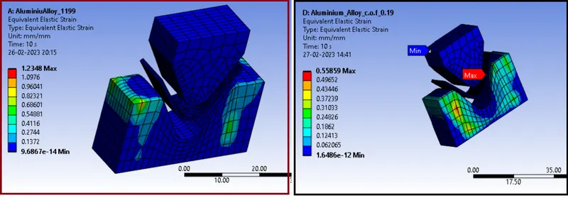
- Strain
- strain Plots
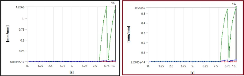
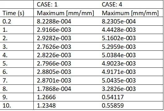
- Detail Strain {CASE:1 & CASE:4} Results:
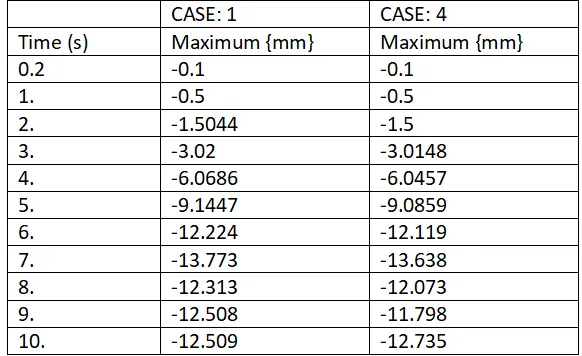
- Deformation
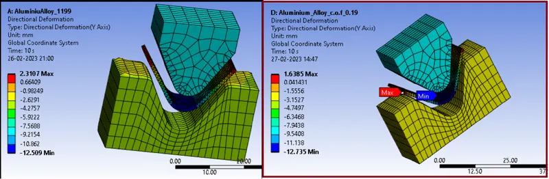
- Deformation Plots:
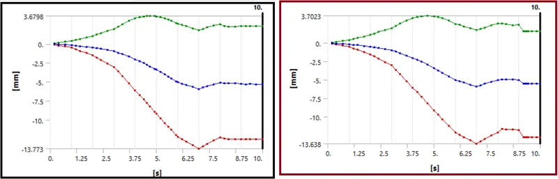
- Detail deformation {CASE:1 & CASE:4} Results:
- Stress for Sheet:
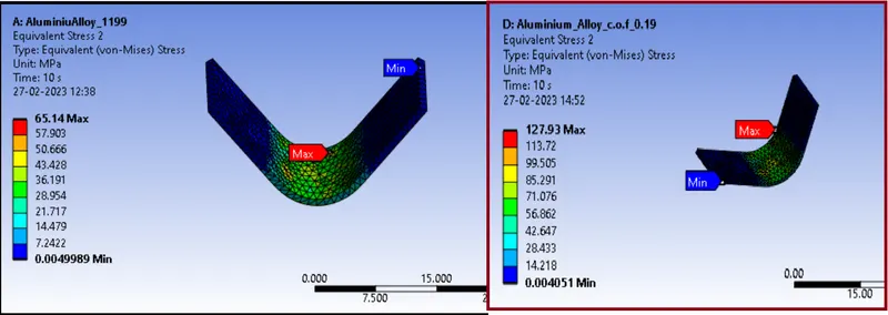
- Stress Plots for Sheet:
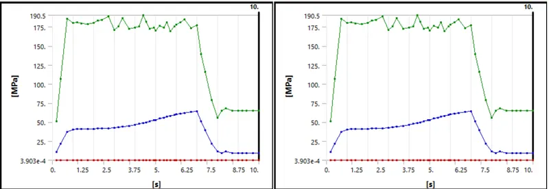
- Detail Stress for sheet {CASE:1 & CASE:4} Results:
*****************************************************************************************************************************
Comparison CASE:1 & CASE:5
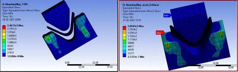
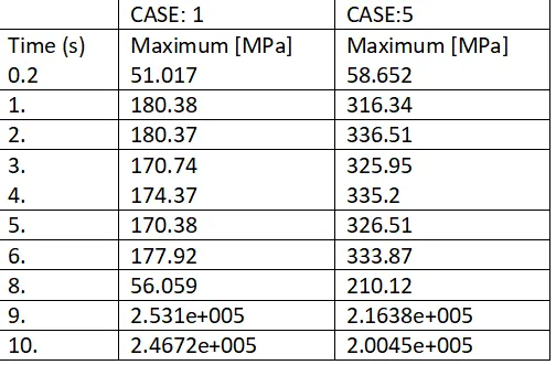
Now we will see the results and comparison of Aluminium Alloy 1199 and Aluminium Alloy (with Refined Mesh)
- Stress
- Stress Plots
- Detail Stress {CASE:1 & CASE:5} Results:
- Strain:
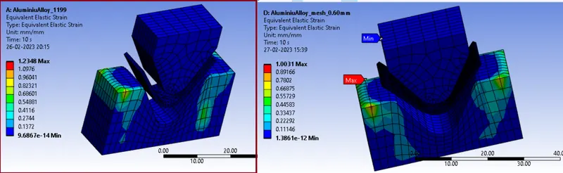
- strain Plots
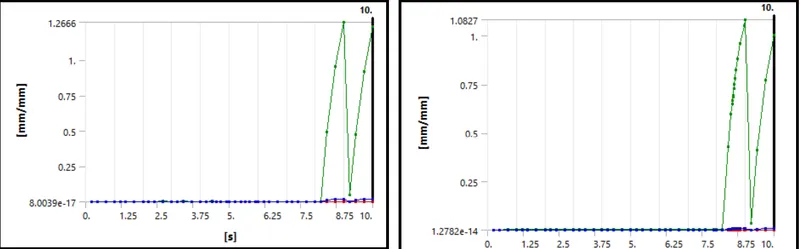
- Detail Strain {CASE:1 & CASE:5} Results:
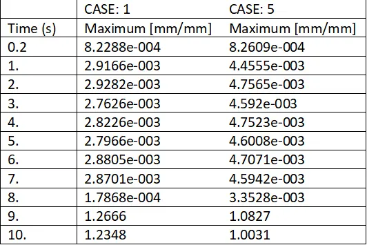
- Deformation
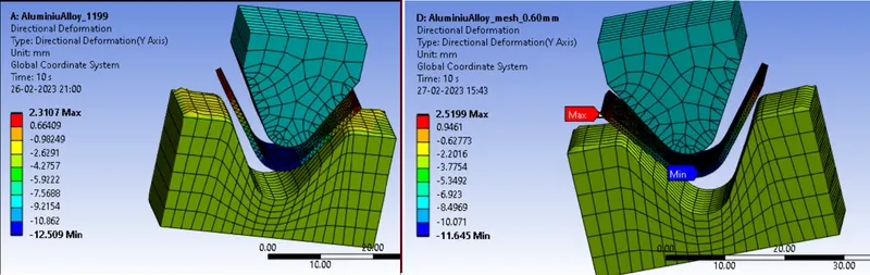
- Deformation Plots:
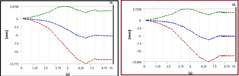
- Detail Deformation {CASE:1 & CASE:5} Results:
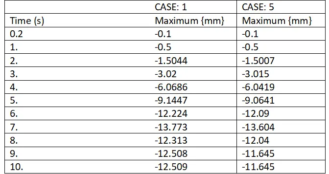
- Stress for Sheet:
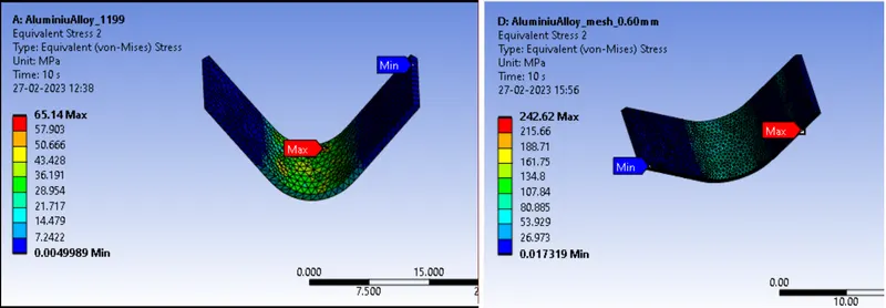
- Stress Plots for Sheet:
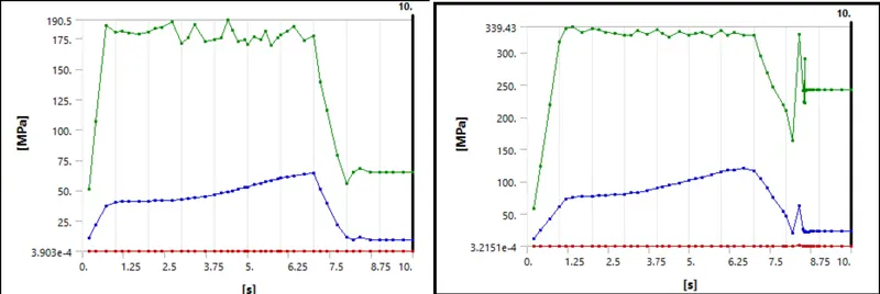
- Detail Stress for sheet {CASE:1 & CASE:5} Results:
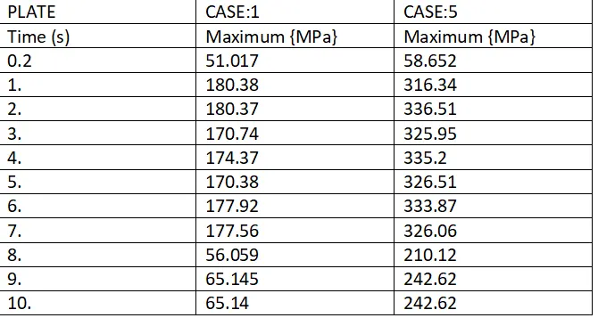
- As in CASE: 4 we can see higher stress values in sheet compared to CASE:1
- In CASE:5 our results having more accuracy due to refinement of Mesh. We can say that higher the refinement of mesh, higher the accuracy of the result.
- For CASE: 5, the material we have used is Aluminium Alloy. This has higher value of Young’s Modulus. And as the Young’s Modulus is higher, stress strain ratio will be higher. So, the Value of stress is also higher in CASE:5.
CONCLUSION:
- In This process sheet/ plates undergo plastic deformation. So, the stress value be higher.
- Depending on the stress concentration and properties of material, bending accuracy can be different.
- Sheet metal bending process is most effective in ductile material {Aluminium, copper} etc.
- As we observed in CASE:1, CASE:2 and CASE:3, among which in CASE: 1, with Aluminium Alloy 1199 has stress concentration in the middle portion can be noticeable.
- Also from the plots, we can observe that there can be an effect of spring break.
- From the comparison of CASE: 1 & CASE: 4, we can conclude that Aluminium Alloy with Coefficient of friction 0.19 give better results than Aluminium Alloy 1199. Because it has higher Young’s Modulus and it can give Elasto-plastic behaviour.
- When we compare CASE: 1 and CASE: 5, we can observe that Aluminium Alloy gives better results as there is a higher stress. We can see perfect stress distribution and good bending behaviour due to refined mesh.
- If we compare results of Aluminium Alloy with Friction coefficient 0.19 and with Friction coefficient 0.1, we can observe from CASE: 4 and CASE: 5, that results are very close in both cases.
- Also, Metal forming with aluminium is a common process used in manufacturing a wide range of products. Aluminium is a lightweight, durable, and corrosion-resistant metal that is easy to work with. aluminium’s excellent properties, combined with the variety of forming methods, make it a versatile and popular material for a wide range of applications.
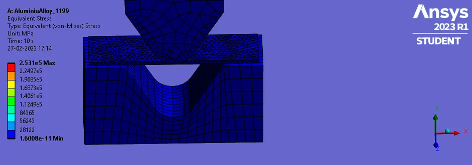
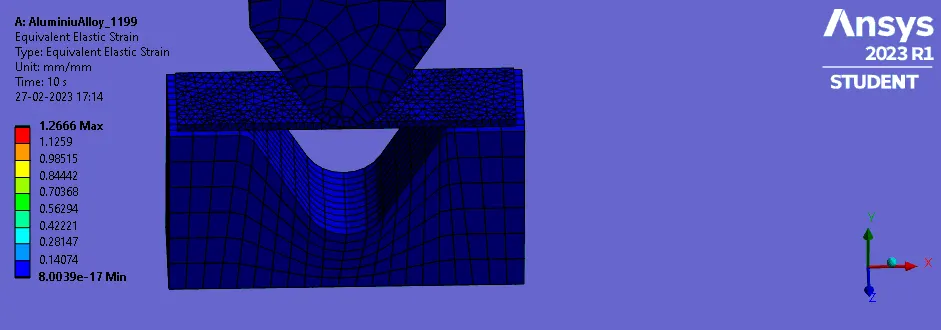
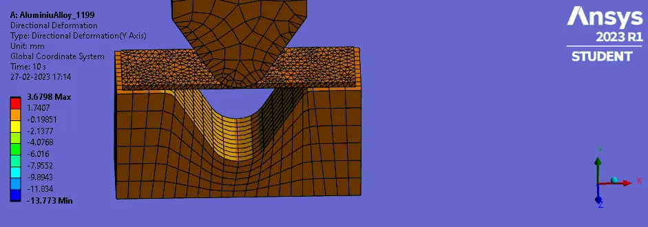
ANIMATION CASE:1
- Stress
- Strain:
- Deformation:
- Stress for Plate
**************************************************************************************************************************************************************************************************************************************************************************END
Here Due to large size of the Ansys file, I have attached a link for the Ansys .wbpz file in below "Model Browse" area.
Kindly find attached link via word document.
Thanks & regards,
Devesh kashyap