Week 1 Stress Concentration on a Plate with hole
AIM: To perform static structural analysis (simulation) to determine the stress concentration on a plate with holes.
OBJECTIVE:
- To Design and simulate the result for plate with single hole.
- To Design and simulate the result for plate with three holes.
- To Comparing the result of the two cases.
THEORY:
- Stress concentration is a phenomenon that occurs when the stress in a material is significantly increased in a localized area, compared to the average stress in the rest of the material. This occurs when there is a sudden change in the shape or geometry of the material, such as a notch, a hole, a crack, or a sharp corner.
- When a force is applied to a material, the stress is distributed throughout the material. However, in areas of geometric irregularities or sharp corners, the stress is not distributed evenly, and the material experiences higher stress in those areas. This can lead to a decrease in the strength of the material, and can eventually cause failure.
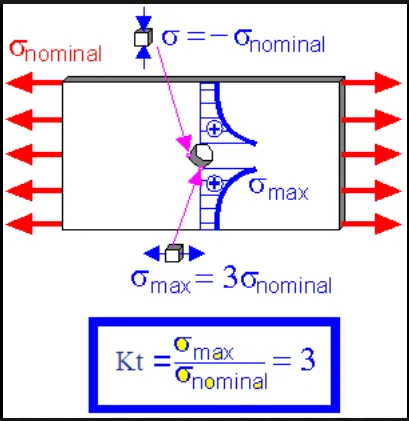
- When a plate is subjected to external loads, such as tension or bending, the stress distribution within the plate is not uniform. In particular, if the plate contains a hole, the stress concentration around the hole can be much higher than in the surrounding material. This is due to the fact that stress tends to concentrate at points where there is a sudden change in the geometry of the material, such as at the edge of a hole.
- The amount of stress concentration around a hole in a plate depends on a number of factors, including the size and shape of the hole, the thickness of the plate, and the type of loading applied to the plate. Typically, the stress concentration factor (SCF) is used to quantify the increase in stress at the edge of the hole, relative to the stress in the surrounding material.
- There are several ways to calculate the SCF for a given hole geometry and loading condition. One common method is to use the equations developed by E. Peterson, which provide approximate solutions for circular holes in plates subjected to tension or bending loads. Another approach is to use finite element analysis (FEA) software to model the plate and calculate the stress distribution and SCF numerically.
- In general, reducing the size of the hole or increasing the thickness of the plate can help to reduce the level of stress concentration. Other techniques for reducing stress concentration around holes include using fillets or chamfers to smooth the transition between the hole and the surrounding material, and adding reinforcing material or patches to distribute the load more evenly.
PROCEDURE/STEPS: -
Case :1Stress Concentration on a Plate with single centre hole
- Very first we need to Open the ANSYS Workbench software. Under the Analysis system select the Static structural and drag the curser into box (shown in the figure ) and wait for few seconds to pop up the window, which contains Engineering data, Geometry, Model, setup, Solution and Results.
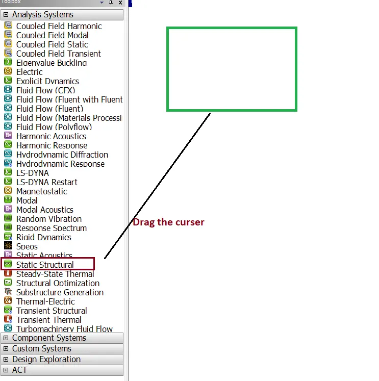
- Rename the static structural as Plate with single hole.
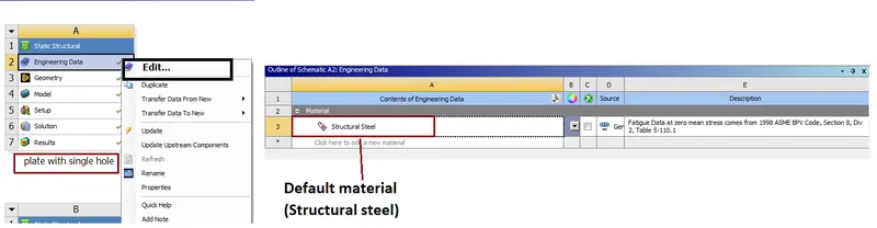
- Update the Default material (Structural steel) to the System, under the Engineering data.
- Now our next step is to Design a rectangular plate with hole by using space claim and assign the Dimensions as per the table
Plate dimensions:
|
Length = 300mm |
|
Height = 120mm |
|
Thickness = 30mm |
Circular Hole at the centre:
Diameter = 60mm
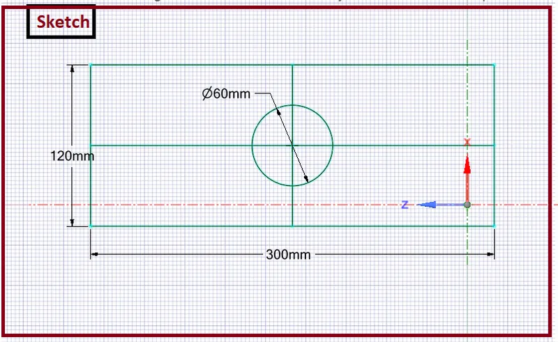
We assign the thickness by using pull option. (Thickness of the plate as 30mm.)
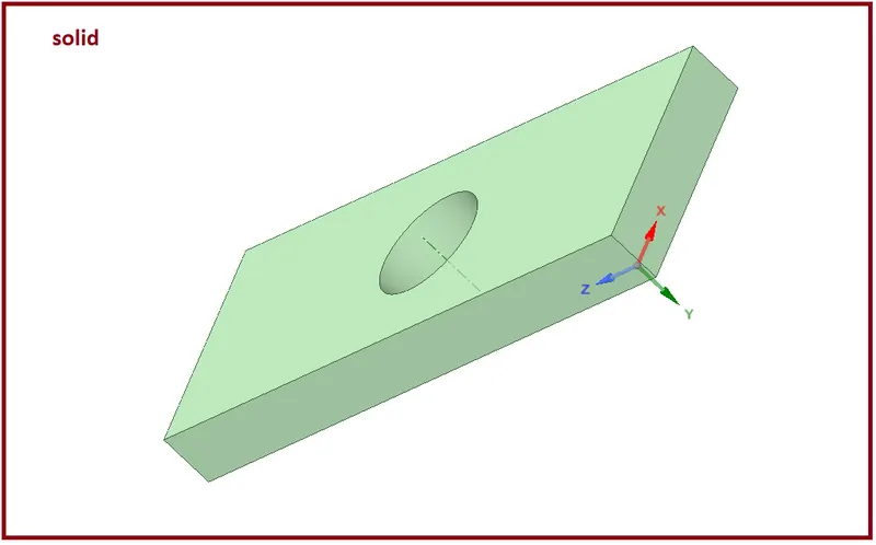
Now we close the space claim window.
- Our next step is right click on Model and hit edit. A new Mechanical browser tab will open.
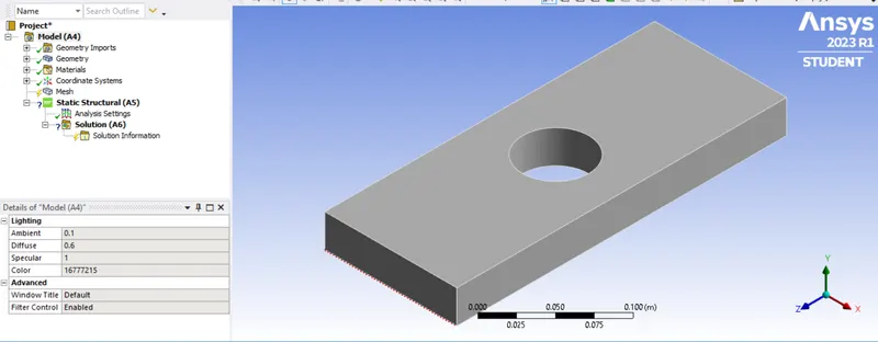
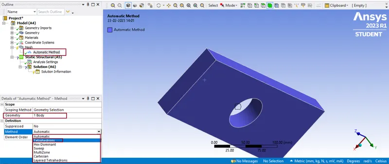
- Here we start our work from meshing tab, as it is a solid structure, we have to change the 2D Element to 3D Element. So, click on mesh and select the insert option. Under insert option select the method and select the geometry as well as under the method, select the tetrahedrons.
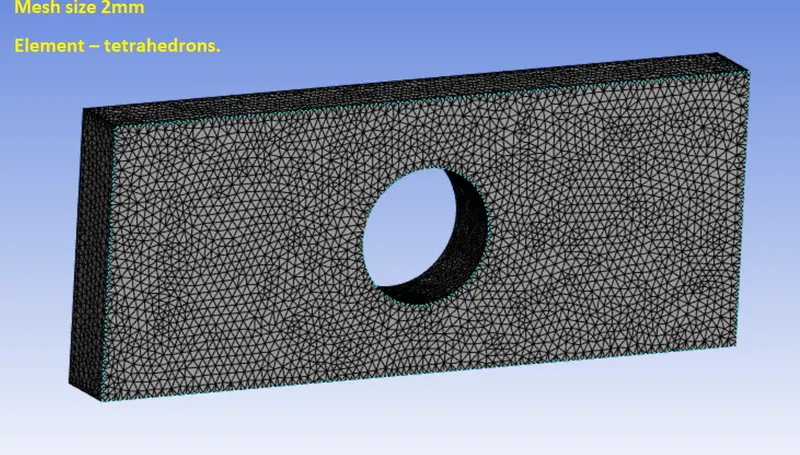
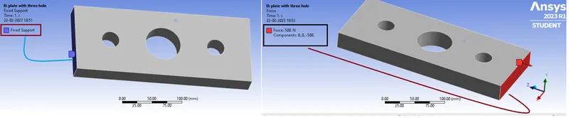
- Now the time for boundary condition settings, In order to get the results we have to fix the left end of the plate by using the fixed support option and apply the tensile force at right side of the plate.
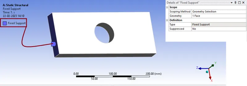
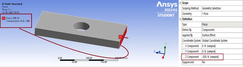
- Now hit solve also we need to Selecting the type of solution that we want that is Total deformation and Equivalent stress and our results are…
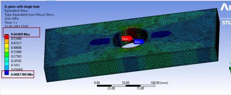
Equivalent (Von-Mises) Stress result
Animation...
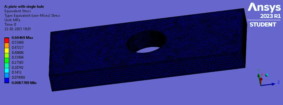
Total deformation:
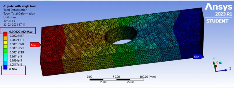
Animation.....
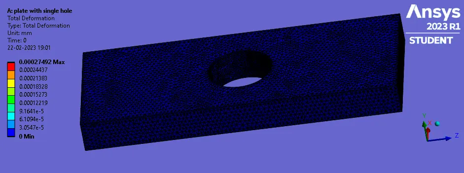
Case :2 Stress Concentration on a Plate with three holes
Here we follow similar steps as we follow previously or we can make duplicate of this project (plate with single hole) and do a single change that is update the geometry and simulate the Model.
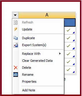
- Rename the duplicate project as plate with three hole
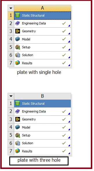
- Here only we need to update the geometry
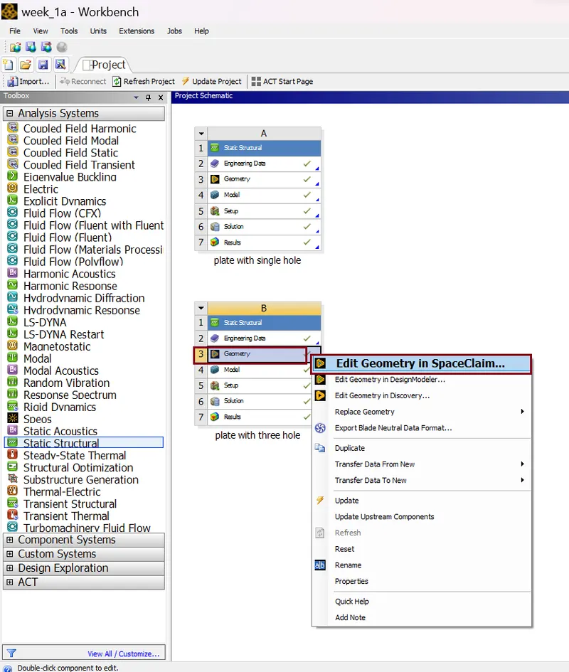
- Make a new geometry.....
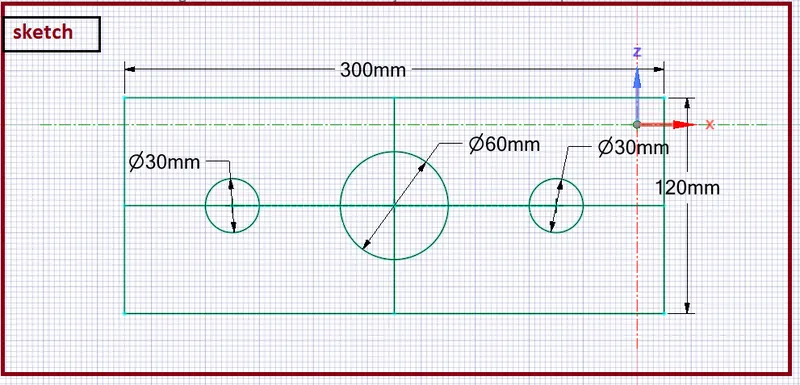
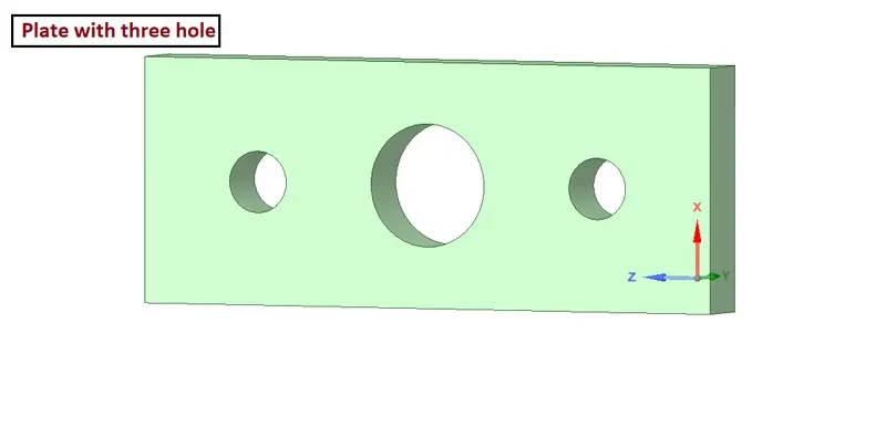
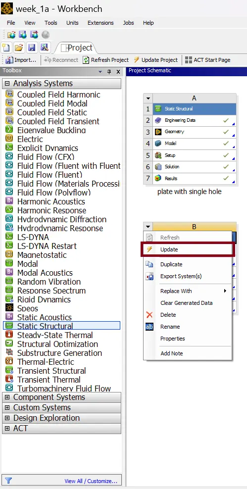
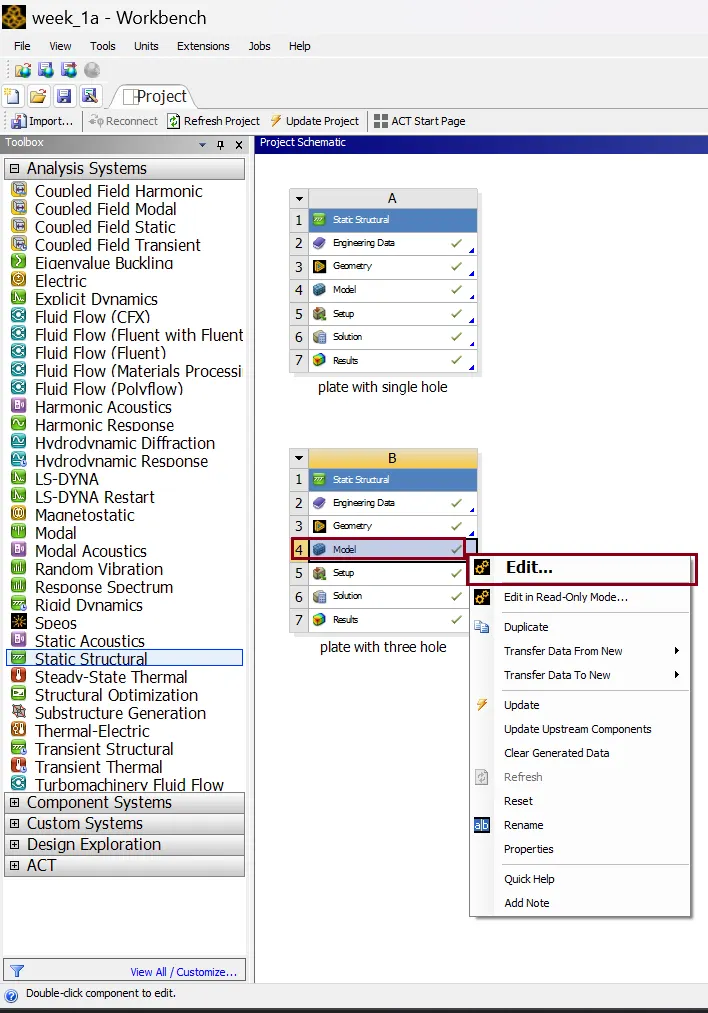
- After that we need to update the project (plate with three hole) as shown below
- after that go to Model >> right click
- Cross check our work….
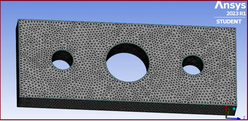
Mesh
boundary condition settings
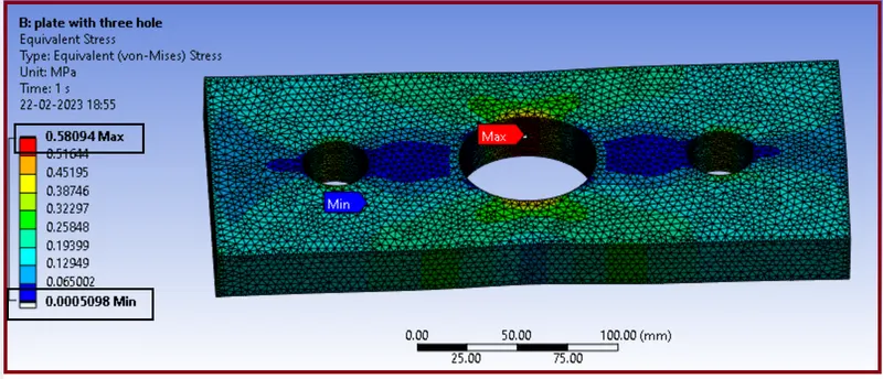
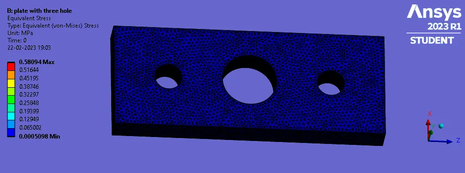
Equivalent (Von-Mises) Stress result
Animation:
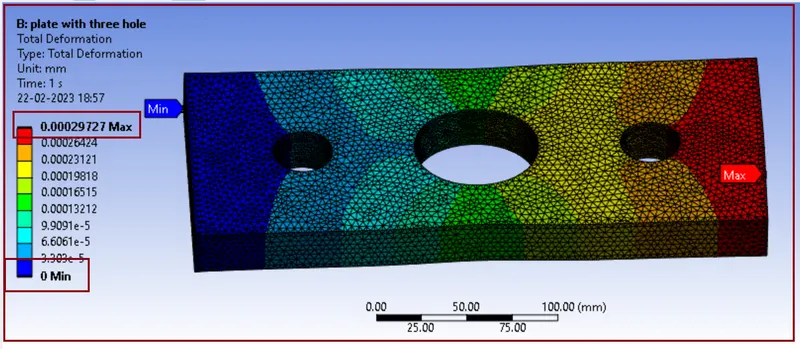
Total deformation:
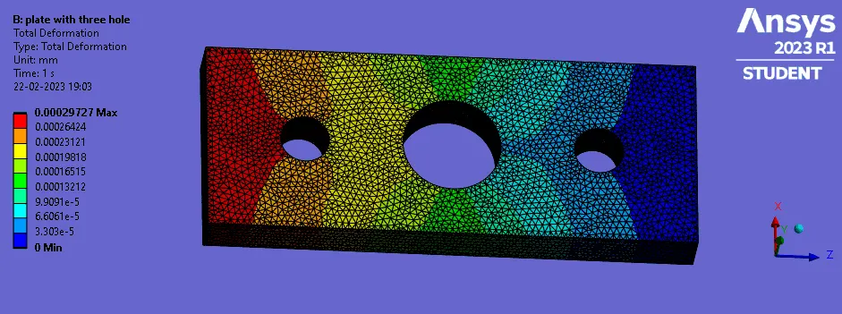
Animation:
RESULTS COMPARISM:
|
S.No. |
|
CASE:1 Plate with a hole |
CASE:2 Plate with Three holes |
|
1. |
Maximum deformation |
2.7492e-004 mm |
2.9227e-004 mm |
|
2. |
Average deformation |
1.3722e-004 mm |
1.4557e-004 mm |
|
3. |
Minimum deformation |
0 |
0 |
|
4. |
Maximum Equivalent stress |
0.60469 MPa |
0.58094 MPa |
|
5. |
Average Equivalent stress |
0.17408 MPa |
0.17081 MPa |
|
6. |
Minimum Equivalent stress |
8.7789e-003 MPa |
5.098e-004 MPa |
CONCLUSION:
- Here we observe that the plate with a hole has less deformation than the plate with three holes.
- Stress developed in the plate with a hole is higher than the stress developed plate with three holes.
From analysis point of view, we can say that choosing plate with three holes because if we compare the stresses, we will have less stress when compared with case: 1. For that reason we had selected the case-2 in analysis point of view.
From manufacturing point of view, we can choose plate with one hole because it has a smaller number of holes which in turn causes less work for application, thus resulting in saving total production cost.
The main concern of any manufacturer is
To reduce the wastage of material
To reduce the production time.
To reduce the cost of production.
So, the first case is very simple in design and requires less time for manufacturing as well as wastage of material will be less, where as in case-2 it requires more time for manufacturing as well as wastage of material will be high.
********************************************************************************************************************************************************************************************************************************************************************************END
Thanks & regards,
Devesh kashyap