Project 2
AIM:- To Developed forward energy-based fuel consumption model for P1 hybrid vehicle.
OBJECTIVE:-
- Tabulate the fuel economy numbers (kmpl) for UDDS and HWFET cycle. Compare these numbers with the baseline numbers for conventional vehicle model from Project 1.
- Plot the time trace for engine, transmission input, transmission output and wheel speed on one plot.
- Plot engine torque, engine power, fuel rate and fuel consumption using subplots.
- Plot accelerator and brake pedal, gear command, vehicle desired and actual speed, vehicle distance using subplots.
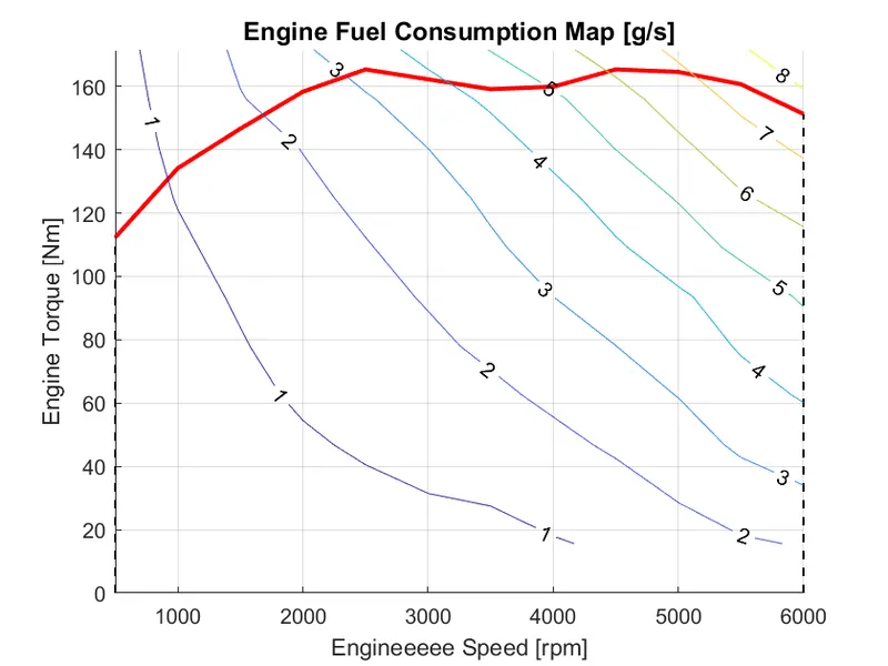
- Plot the engine operating points on the engine fuel map.
- Plot motor speed, torque, motor input power using subplots.
- Plot pack voltage, current and SoC using subplots.
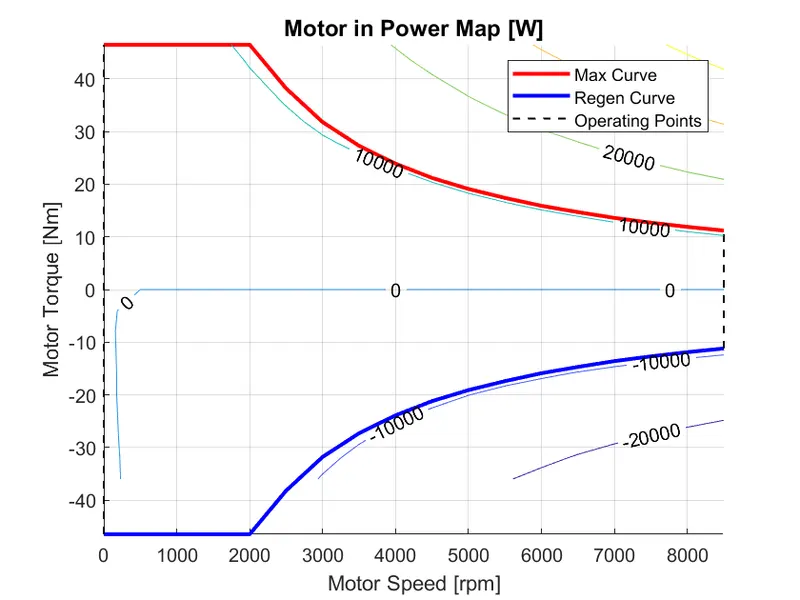
- Plot the motor operating points on the motor input power map, with the motor max motoring and generating torque curves.
- Generate the plots for both drive cycles.
THEORY:-
Hybrid electric vehicles (HEVs) are more famous around the worlds. It a combination an internal combustion engine and electric motors – battery. HEVs combine the benefits of high fuel economy and low vehicle emissions with the power and range of conventional vehicles. A hybrid combines at least one electric motor with a gasoline engine to move the car, and its system recaptures energy via regenerative braking. Sometimes the electric motor propel the vehicle and sometimes it's the IC engine, and sometimes they work together.
Hybrid electric vehicles will generally have two energy sources and converters. One will usually be a bidirectional energy source and converter. And other can be bidirectional or a unidirectional one. Due to the bidirectionality of one power train, multiple energy/power flow path can be achieved. increases flexibility of operation.
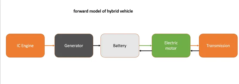
P1 Hybrid
Multiple powerplants power the wheels together i.e., in parallel. Engine and electric motor output power are combined mechanically before going to the wheels. The engine and electric motor both can provide power to the wheels individually or together. Generally, the engine is connected to the wheels using a conventional transmission. There are multiple ways to mechanically coupled the electric motor, in parallel with the engine, to the wheels.
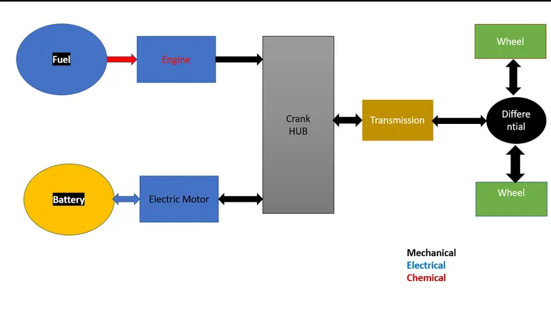
Operation Modes:
Pure electric driving: traction motor propels vehicle using the energy stored in the battery. Engine is off.
Pure engine driving: Engine powers the wheel, Electric motor is off.
Hybrid driving: Energy from fuel-engine and battery-electric motor used to propel the vehicle.
Engine driving and battery charging: Engine used for propulsion and to charge battery.
Regenerative braking: Vehicles kinetic energy used to charge battery through electric motor breaking.
Battery charging: Engine charges the battery through the electric motor, No propulsion.
Hybrid battery charging: Both engine and traction motor (through regen) charge battery.
Now we are interested to design P1 Hybrid vehicle (Honda Insight). we have some vehicle data, now we write MATLAB script to load these data in my MATLAB workspace and then we start making appropriate model for P1 Hybrid.
VEHICLE MODEL
Pre-Processing MATLAB script to load all the variables in the workspace.
%% Skill-Lync -> Hybrid Drives Development
% Project 2 - P1 Hybrid Vehicle Model
% By - DEVESH KASHYAP

% Description:

%% Initialization File
% Initialization file for loading the variables for the Conventional vehicle simulation model

%% Vehicle Parameters
M = 1500;       % Vehicle weight [kg]
Cr = 0.015;     % Rolling resistance coefficient
Rw = 0.35;      % Rolling radius [m]
Cd = 0.33;      % Drag coefficient
Af = 2;         % Frontal area [m2]
rhoa = 1.225;   % Air density [kg/m3]
Vwind = 0;      % Wind velocity [kmph]
g = 9.81;       % Gravitational acceleration [m/s2]
theta = 0;      % Slope [deg]
myu_road_tire = 1; % Coefficient of friction between tire - road interface

%% Powertrain Parameters
FDR = 3.73;                         % Final Drive Ratio / Diff Ratio
DiffEff = 0.99;                     % Differential efficiency (assumed independent of operating conditions)

NumGear = 4;                        % Number of gears in transmission
TransGear = [1:NumGear];            % Transmission Gears
TransRatio = [3.06, 1.62, 1, 0.7];  % Corresponding Transmission ratios
TransEff = 0.90;                    % Transmission efficiency (assumed independent of operating conditions)

TC_SR = [0, .5, .6, .7, .8, .87, .92, .94, .96, .97, 1];   % Torque Converter Speed Ratio (Matlab default) -> TurbSpd/PumpSpd
TC_TR = [2.232, 1.5462, 1.4058, 1.2746, 1.1528, 1.0732, 1.0192, 1, 1, 1, 1];   % Torque Converter Torque Ratio (Matlab default) -> TurbTrq/PumpTrq
TC_Cf = 1e-4 * [.72558, .66322, .63463, .59042, .51331, .4144, .29287, .22444, .12186, .04386, 0]; % Torque Converter Capacity Factor (Matlab default) -> PumpTrq/PumpSpd^2 [Nm/rpm^2]

load Vehicle_Data/Engine_data_1_9L_Saturn_95kW
load Vehicle_Data/Trans_Shift_map
load Vehicle_Data/EM_Honda_Insight_10kW
load Vehicle_Data/ESS_NiMH6


ESS_init_soc = 0.8;
ESS_soc_max = 0.9;
ESS_soc_min = 0.6;


%% Driver Parameters
Kp = 10;                    % P gain for driver PI model
Ki = 1;                     % I gain for driver PI model
Drive_Cycle_Select = 1;     % Drive cycle selection

% Drive cycle values in m/s

if Drive_Cycle_Select == 1
    load DriveCycles/UDDS;

elseif Drive_Cycle_Select == 2
    load DriveCycles/HWFET;

elseif Drive_Cycle_Select == 3
    load DriveCycles/FTP;

elseif Drive_Cycle_Select == 4
    load DriveCycles/US06;

elseif Drive_Cycle_Select == 5
    load DriveCycles/NEDC;

elseif Drive_Cycle_Select == 6
    load DriveCycles/WLTP;

end

time_end = cyc_time(end);
vel_end = cyc_vel(end);
Here we select Drive Cycle from above MATLAB Script, By changing the variable Drive_Cycle_Select to
|
1 |
UDDS |
|
2 |
HWFET |
|
3 |
FTP |
|
4 |
US06 |
|
5 |
NEDC |
|
6 |
WLTP |
Now we construct vehicle model one by one.Firstly, we create three subsystem blocks Driver, Controller and Powertrain.
MAIN MODEL:-
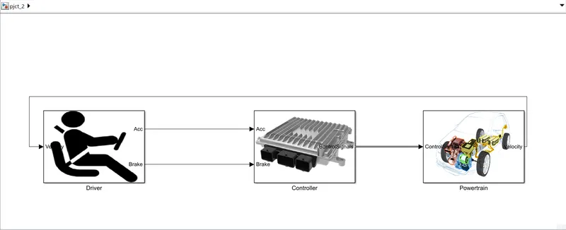
Driver controller is required to control the vehicle to follow a desired speed.The controller is implemented to model the driver that will either push the accelerator or the brake pedal to match the desired speed which enables to study the driver behaviour. The actual vehicle speed is given as feedback to the driver block, and the driver block gives the controller block the required acceleration or brake output, while the controller block provides control signals for the Powertrain model.
- Driver Model:-
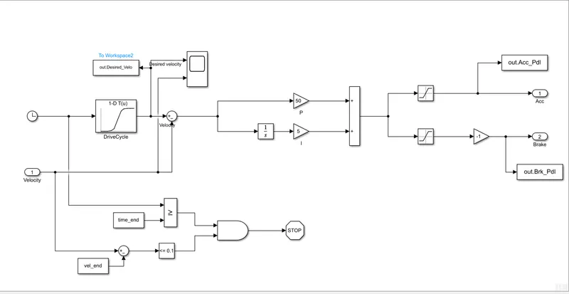
Driver block is power input block which regulate acceleration and brake pedal to achieve desired output speed. Here we connect Drive cycle data and velocity data to scope for comparison between desired speed and actual speed.
- Controller Block:
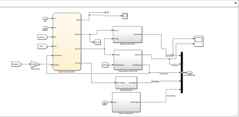
The main brain of entire vehicle is controller block/Model. It having electronic control units based on driver input it generates engine torque, motor torque, desired transmission gear and brake torque these data are fed to the Powertrain block.
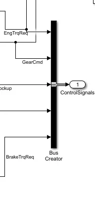
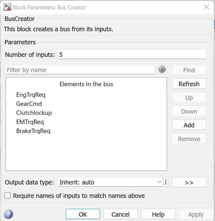
A state flow chart is used to represent the supervisory control unit, it decides the operating mode while it is start/stop mode or cruising mode or regen braking mode. for each modes the Engine drive and the electric motor drive are controlled. It has four subsystem blocks – Engine control unit, Transmission control unit, EM control unit, Brake control unit and a Bus creator to store data.
- supervisory control unit
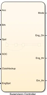
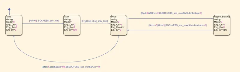
Here acceleration, Brake, Engine speed, vehicle speed, state of charge and ClutchLockup are input data and Mode, Engine On/off request, Engine input throttle and Electric motor input Throttle are output data.
- Engine Control unit:
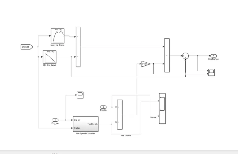
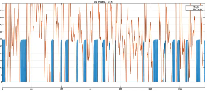
it compares engine speed with the maximum torque and minimum torque curves of the lookup table and give the required torque command to the engine block. The throttle input is combined with the idle speed throttle and gains with the torque output from the lookup table to estimate the torque input required for the engine.
it has one more subsystem block which is Idle Speed Controller.
The engine on/off feature can be implemented in this model to eliminate idle losses for the engine. by eliminating idle throttle for engine off conditions.
- Idle Speed Controller
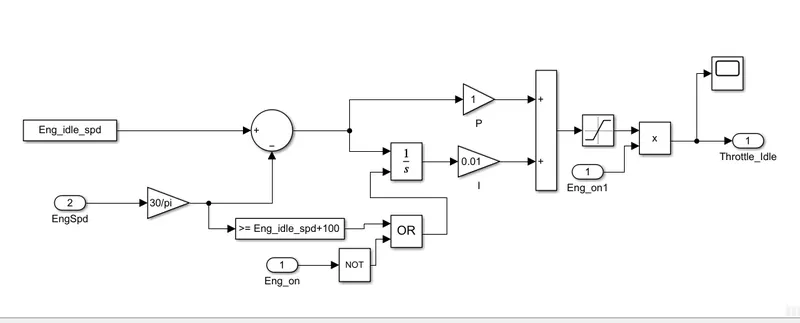
- Transmission Control
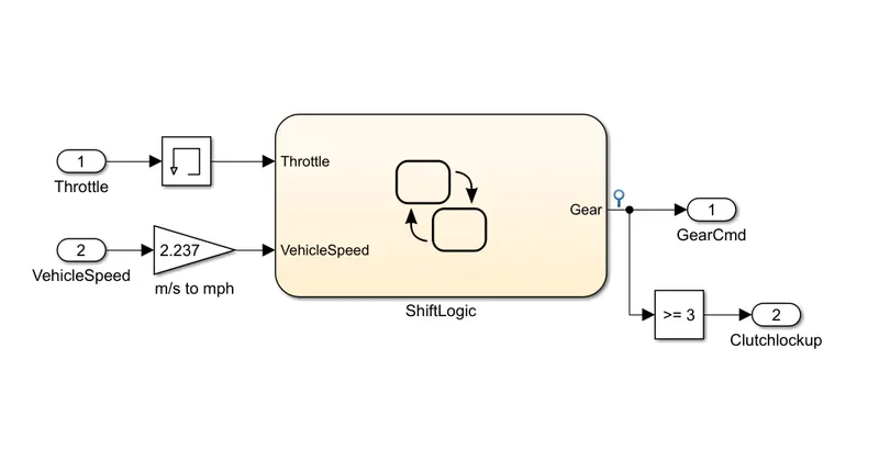
It controls the gear shifting by the use of study flow chart. The gear shift is controlled by vehicle speed and throttle it is determined whether the clutch is locked up or not. If the gear selection is greater than or equal to 3, the clutch will lock.
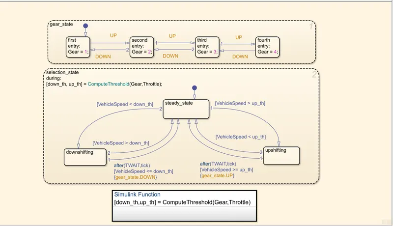
- Electric Motor Control Unit
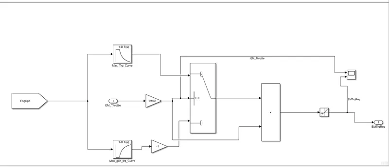
It compares EM speed with the maximum torque curve and maximum torque generation curves of the lookup table and give the required torque command to the Electric Motor. The EM throttle input is used to compare the lookup tables and to estimate the torque input required for the E-Motor for the drive.
- Brake control unit
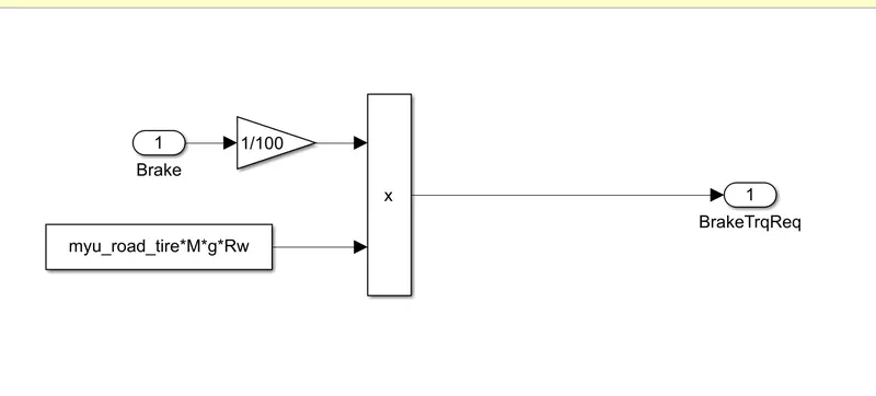
Brake control unit it produced required brake torque according to the brake pedal movement. And passes the brake torque to the wheel block in the transmission Model (under the powertrain subsystem).
- BusCreator:
- Powertrain Block
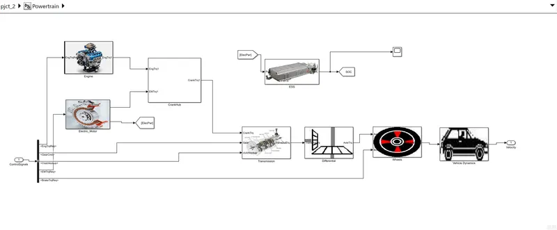
it includes Engine block, Electric motor block, Crank Hub, ESS (energy storage system), Transmission Block, Differential Block, Wheel Block and Vehicle Dynamic Block. These all blocks represent a subsystem block. It includes all the components that convert the power of the engine into vehicle motion.
- Engine Block
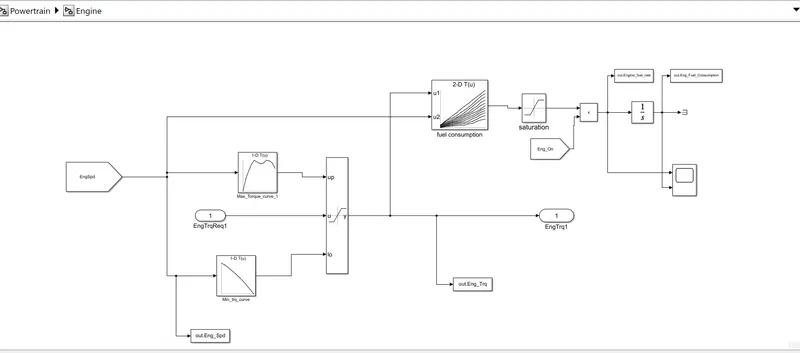
The required torque from the controller is saturated between Max torque curve and min torque curve Based on the Engine speed and passes the Engine torque to the Crank Hub. The 2D lookup table is used to calculate the fuel flow rate based on engine speed and engine torque. The fuel flow rate is then integrated to find the fuel consumption. The new engine also has an on / off feature to eliminate the fuel flow rate when the engine is off. Also, the engine torque cannot be negative torque as minimum torque curve made saturated. Estimated fuel flow rate, fuel consumption, engine torque and engine speed are passed to the MATLAB workspace using the to-workspace block. Engine fuel flow rate and Fuel consumption are scoped.
- Electric Motor Block
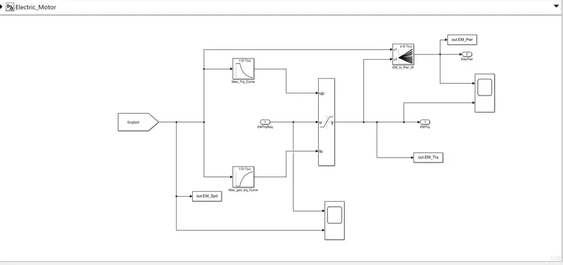
The required EM torque from the controller is saturated between Max EM torque curve and max EM torque Generation curve Based on the Engine speed and passes the EM torque to the Crank Hub. The 2D lookup table is used to calculate the Input Electric Power to the Motor based on EM speed and EM torque.
- Battery Block / ESS Block:
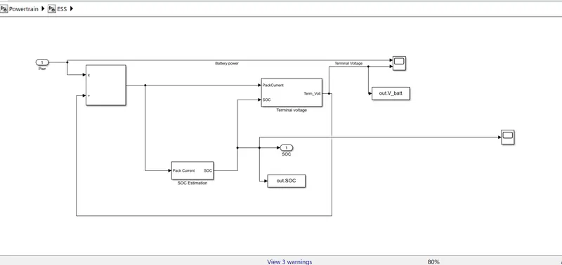
Here we create a battery pack subsystem in this subsystem Electric power termed as input, and Battery SOC is termed as output. Two different subsystem blocks have been created to determine the SOC and terminal voltage separately, the SOC being used to calculate the terminal voltage.
- SOC Estimation Block
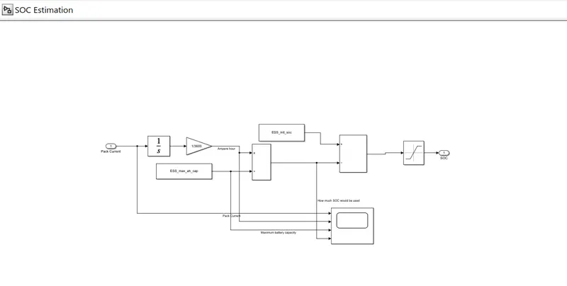
The value of SOC lies between 0.68 to 0.98 practically. Pack current in Ampere is converted to Ah (Ampere per hour) and divides with Max Capacity and adds with the Initial SOC to determine the SOC of the battery at each instance, the SOC value is limited between 0 -- 1.
- Terminal Voltage Block
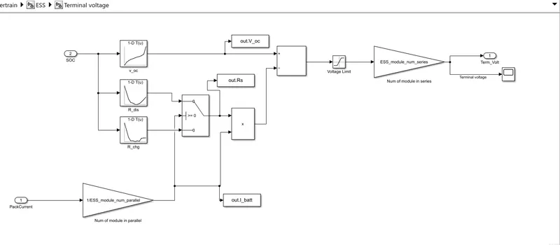
Internal resistance and Ideal voltage are determined by 1D lookup tables, and battery voltage is determined using the model. Specified values are sent back to workspace using the 'Two Workspace' block and can used for post processing.
- Crank Hub Block
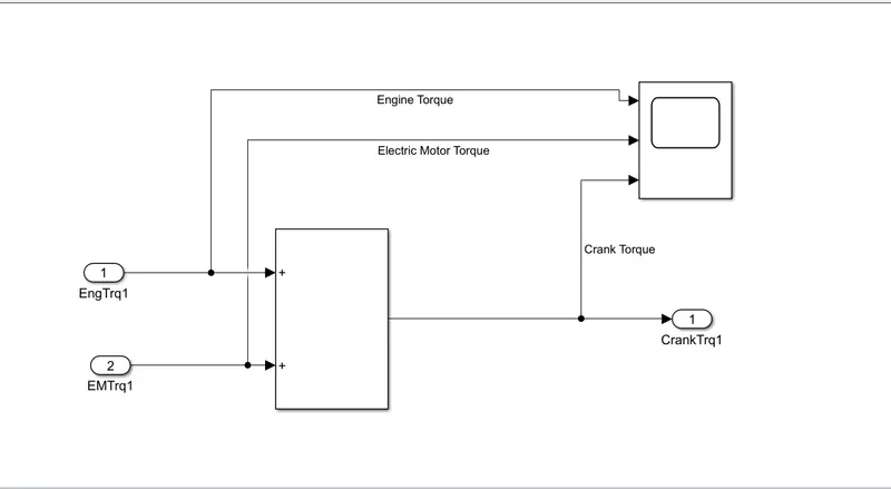
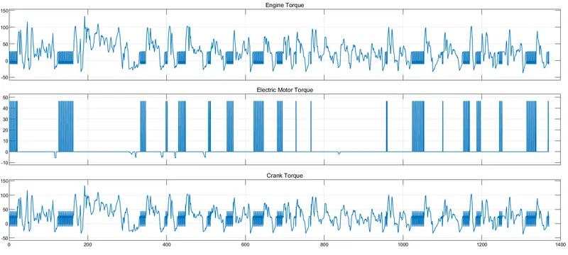
Its main function is addition of Torque (EM torque and Engine Torque) and pass it to the transmission block as the crank torque.
- Transmission Block
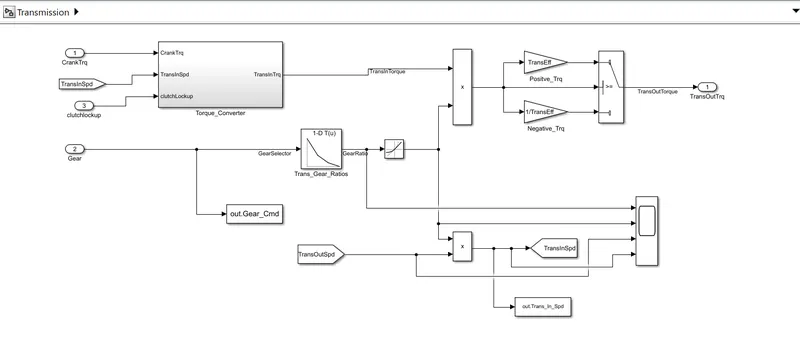
Here we add ClutchLockUp feature in this Hybrid version. Crank is connected to the automatic transmission via a torque converter. The output of the transmission is connected to the differential. gear selection from the transmission control unit is multiplied by the engine torque in this block, and the efficiency and engine dynamics of the torque converter are applied in this model. It has one subsystem name as Torque_Convertor.
- Torque Converter Block
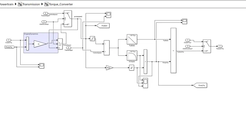
it defines the pump and turbine torque by the clutch lock up status, and the combination gives us the desired transmission torque. Pump and turbine combination are used in automatic transmission.
- Differential Block
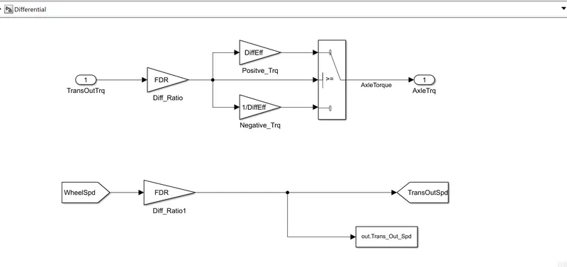
Transmission output torque is multiplied by the differential gear ratio and differential efficiency in this block and the torque is transmitted to the wheel as the axle torque.
- Wheel Block
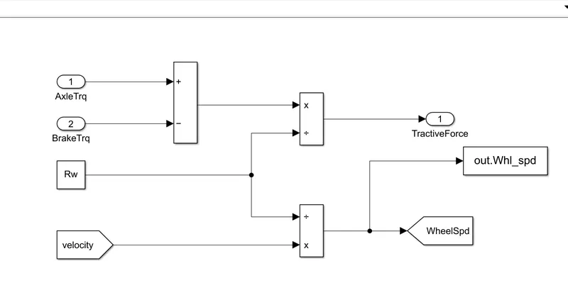
Wheel speed is calculated from the vehicle velocity and saved in the workspace. The brake torque from the control model is subtracted from the Axle torque and divides from the rolling radius to determine the Tractive force.
- Vehicle Dynamics Block
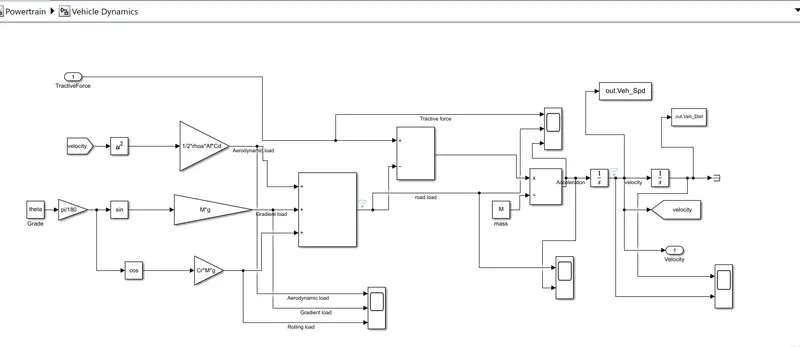
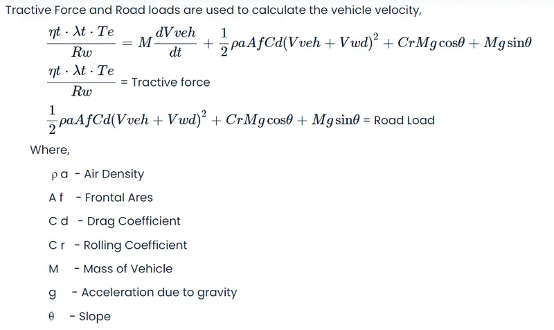
The Road load and longitudinal vehicle dynamics are represented by above block. Tractive Force and Road loads are used to calculate the vehicle velocity....
SIMULATION RESULTS (SCOPE):
UDDS Drive Cycle
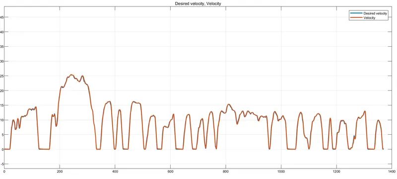
- Desired velocity Vs Actual Velocity
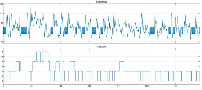
- Engine Torque required vs Gear Cmd
- Idle Throttle and Throttle
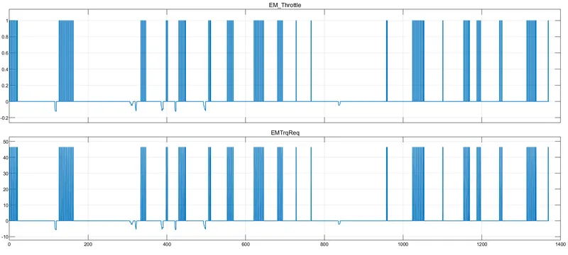
- Electric Motor throttle and EM Trq Req (electric motor torque required)
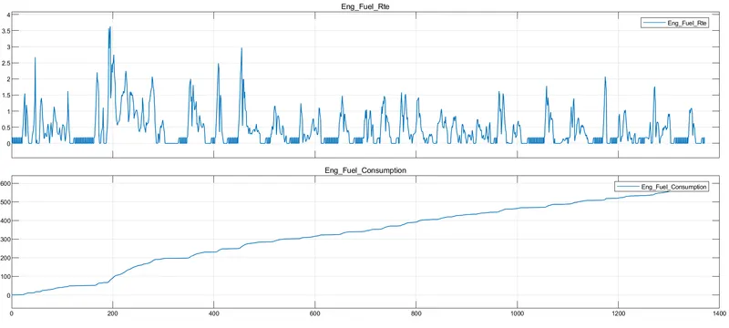
- Engine Fuel Consumption and engine fuel Rate
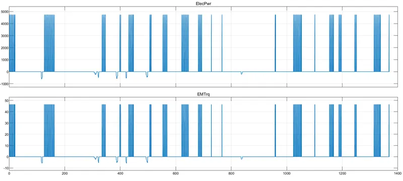
- Electric Motor Power and Electric Motor Torque
- Engine Torque, EM Torque and Net Crank Torque
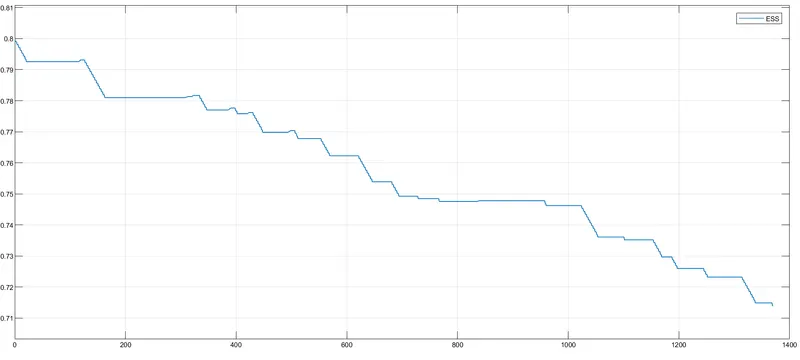
- SOC of ESS
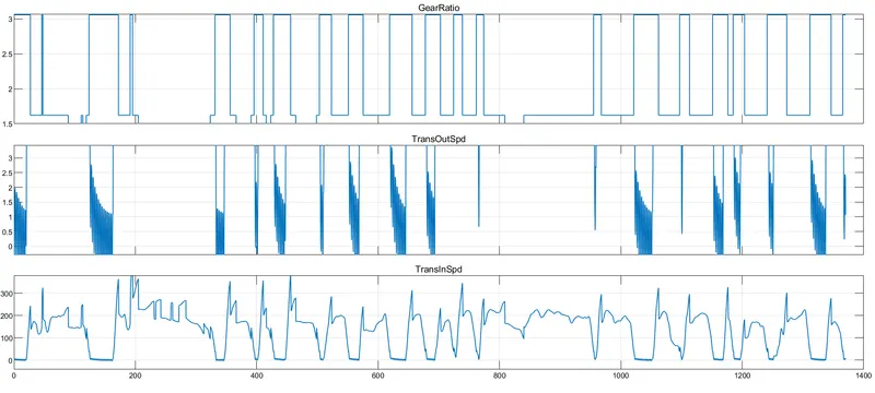
- Transmission input and output speed with gear ratio
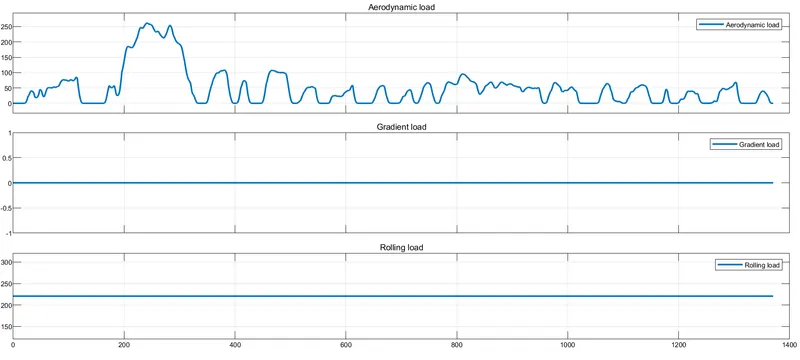
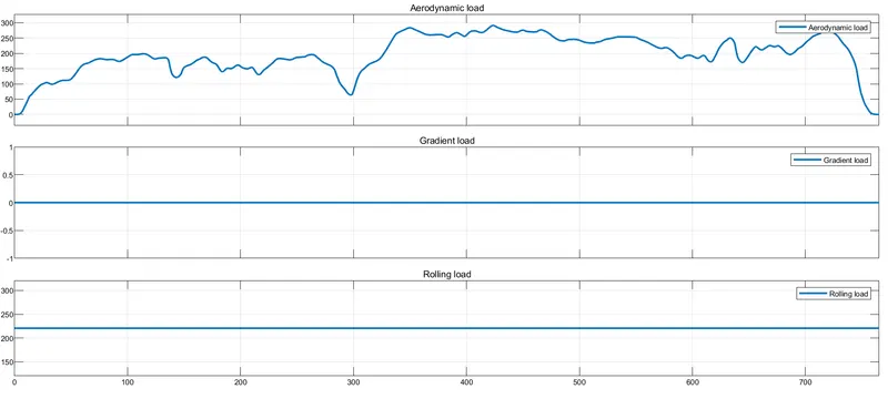
- Road Load
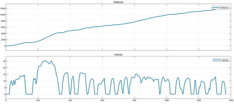
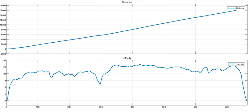
- Velocity and distance
HWFET Drive Cycle
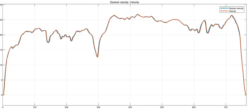
- Desired velocity Vs Actual Velocity
- Engine Torque required vs Gear Cmd
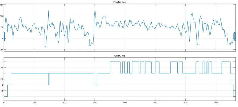
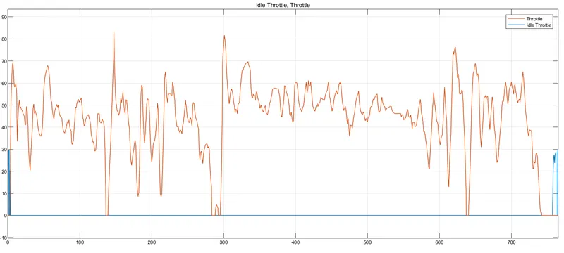
- Idle Throttle and Throttle
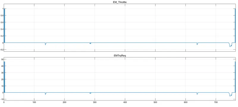
- Electric Motor throttle and EM Trq Req (electric motor torque required)
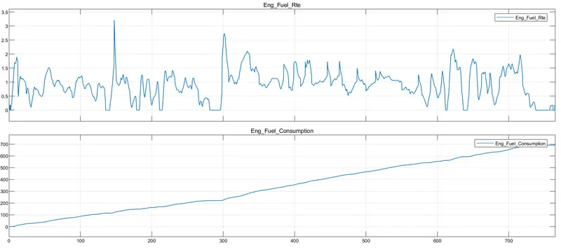
- Engine Fuel Consumption and engine fuel Rate
- Electric Motor Power and Electric Motor Torque
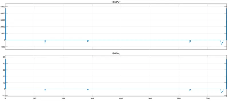
- Engine Torque, EM Torque and Net Crank Torque
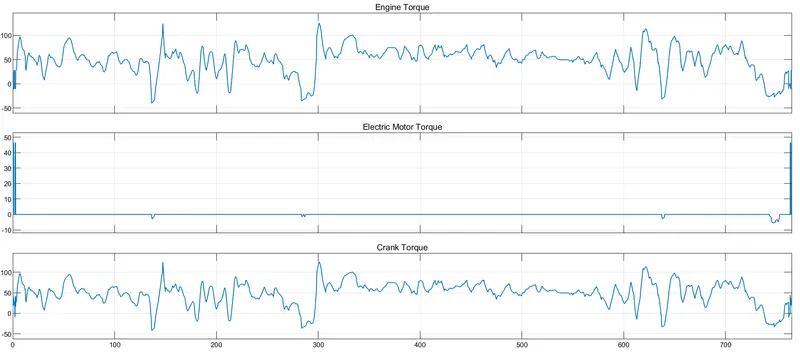
- SOC of ESS
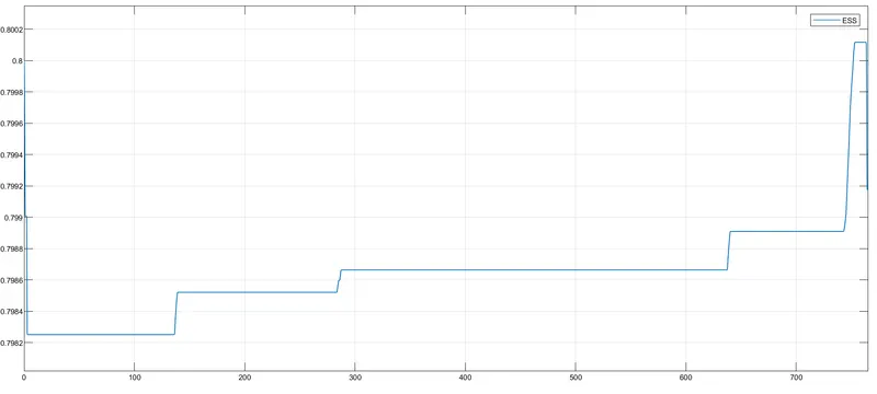
- Transmission input and output speed with gear ratio
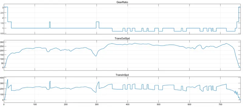
- Road Load
- Velocity and distance
POST-PROCESSING
MATLAB script for analysis and plots
%% Renaming variables
Time = out.tout;
Acc_Pdl = out.Acc_Pdl;          % Accelerator pedal [%]
Brk_Pdl = out.Brk_Pdl;          % Brake pedal [%]
Gear_Cmd = out.Gear_Cmd;        % Transmission gear
Trans_In_Spd = out.Trans_In_Spd*30/pi;  % Transmission input speed [rpm]
Trans_Out_Spd = out.Trans_Out_Spd*30/pi;% Transmission output speed [rpm]
Eng_Trq = out.Eng_Trq;          % Engine brake torque [Nm]
Eng_Spd = out.Eng_Spd*30/pi;    % Engine speed [rpm]
Eng_Fuel_Consump = out.Eng_Fuel_Consumption;    % Engine fuel consumption [g]

Eng_Fuel_rate = out.Engine_fuel_rate   ;
Veh_Dist = out.Veh_Dist/1000;   % Distance traveled by vehicle [km]
Veh_Spd = out.Veh_Spd*18/5;     % Vehicle speed [kmph]
Whl_Spd = out.Whl_spd*30/pi;    % Wheel speed [rpm]
A =sum(Veh_Dist) ;
% Desired_spd = out.Desired_Velo*18/5; % Desired Speed [Kmph]
EM_Spd = out.EM_Spd*30/pi;            % E Motor Speed [rpm]
EM_Trq = out.EM_Trq;            % E Motor Torque [Nm]
EM_Pwr = out.EM_Pwr;            % Motor Input Power [W]
V_batt = out.V_batt;            % Battery Pack Voltage [v]
I_batt = out.I_batt;            % Battery Pack Current [A]
SOC = out.SOC;                  % SOC [%]

%% Data Analysis
Eng_Pwr = Eng_Spd.*pi/30.*Eng_Trq/1000;   % Engine brake power [kW]
rho_petrol = 0.7197;                    % Density of petrol [kg/L]
kmpl = Veh_Dist(end)/(Eng_Fuel_Consump(end)/1000/rho_petrol);    % Fuel economy [kmpl]


%% Average speed, Maximum speed and Fuel economy
Avg_speed = sum(Veh_Spd)/length(Veh_Spd);
Max_Speed = maxk(Veh_Spd,1);
table(Avg_speed,Max_Speed,kmpl,'VariableNames',{'Average Speed [kmph]','Maximum Speed [kmph]','Fuel Economy [kmpl]'})


%% Plotting vehicle characteristics time trace
figure(1)
subplot(3,1,1)
hold on
grid on
plot(Time, Acc_Pdl, 'linewidth', 1, 'Color', 'black');
plot(Time, Brk_Pdl, 'linewidth', 1, 'Color', 'red');
ylabel('Pedal [%]')
xlim([0, Time(end)]);
legend('Accel','Brake');
subplot(3,1,2)
hold on
grid on
plot(Time, Trans_In_Spd, 'linewidth', 1, 'Color', 'black');
plot(Time, Trans_Out_Spd, 'linewidth', 1, 'Color', 'red');
ylabel('Speed [rpm]')
xlim([0, Time(end)]);
ylim([0, 6000]);
legend('Trans Input','Trans Output');
subplot(3,1,3)
hold on
grid on
plot(Time, Gear_Cmd, 'linewidth', 1, 'Color', 'black');
xlim([0, Time(end)]);
xlabel('Time [s]');
ylabel('Gear');

%% Plotting engine operating points on engine fuel map
figure('Name','Engine Operating Points');
hold on
grid on
title('Engine Operating Points','fontsize',12);
p1=plot(Eng_map_spd*30/pi,Eng_max_trq,'linewidth',2,'color','r');
p2=line([Eng_map_spd(end)*30/pi Eng_map_spd(end)*30/pi],[0 Eng_max_trq(end)]);
set(p2,'linewidth',1,'linestyle','--','color','k');
p3=line([Eng_map_spd(1)*30/pi Eng_map_spd(1)*30/pi],[0 Eng_max_trq(1)]);
set(p3,'linewidth',1,'linestyle','--','color','k');
[c,h] = contour(Eng_map_spd'*30/pi,Eng_map_trq,Eng_fuel_map');
clabel(c,h);
xlabel('Engineeeee Speed [rpm]');
ylabel('Engine Torque [Nm]');
title('Engine Fuel Consumption Map [g/s]');

%% Engine power,Engine Torque,Engine fuel rate and Engine fuel consumption
figure(2)
subplot(4,1,1)
hold on
grid on
plot(Time, Eng_Trq, 'linewidth', 1, 'Color', 'B');
ylabel('Torque [Nm]')
xlim([0, Time(end)]);
xlabel('Time [s]');
subplot(4,1,2)
hold on
grid on
plot(Time, Eng_Pwr, 'linewidth', 1, 'Color', 'G');
ylabel('Power [KW]')
xlim([0, Time(end)]);
xlabel('Time [s]');
subplot(4,1,3)
hold on
grid on
plot(Time, Eng_Fuel_rate, 'linewidth', 1, 'Color', 'R');
xlim([0, Time(end)]);
xlabel('Time [s]');
ylabel('Engine Fuel rate');
subplot(4,1,4)
hold on
grid on
plot(Time, Eng_Fuel_Consump, 'linewidth', 1, 'Color', 'Black');
xlim([0, Time(end)]);
xlabel('Time [s]');
ylabel('Fuel Consumption [gram]');
%% Plotting Drive Cycle
figure(3)
hold on
grid on
plot(cyc_time, cyc_vel, 'linewidth', 1, 'Color', 'R');
xlabel('Time [s]')
ylabel('Velocity [Mph]')
title('Drive Cycle')


%% EM
%% EM
% Plotting Motor Speed, Motor torque and Motor Input power
figure(6)
subplot(3,1,1)
hold on
grid on
plot(Time, EM_Spd, 'linewidth', 1, 'Color', 'R');
ylabel('Speed [rpm]')
xlim([0, Time(end)]);
title('Motor Speed')
subplot(3,1,2)
hold on
grid on
plot(Time, EM_Trq, 'linewidth', 1, 'Color', 'G');
ylabel('Torque [Nm]')
xlim([0, Time(end)]);
title('Motor Torque')
subplot(3,1,3)
hold on
grid on
plot(Time, EM_Pwr, 'linewidth', 1, 'Color', 'magenta');
xlim([0, Time(end)]);
xlabel('Time [s]');
ylabel('Power [W]');
title('Motor Input Power')

%% BATTERY
% Plotting Pack Current, Voltage and SOC
figure(7)
subplot(3,1,1)
plot(Time,V_batt,'LineWidth',1)
xlabel('Time [s]');
ylabel('Voltage [v]');
title('Pack Voltage')
xlim([0, Time(end)]);
grid on
subplot(3,1,2)
plot(Time,I_batt,'LineWidth',1)
xlabel('Time [s]');
ylabel('Current [A]');
title('Battery Current')
xlim([0, Time(end)]);
grid on
subplot(3,1,3)
plot(Time,SOC,'LineWidth',1)
xlabel('Time [s]');
ylabel('SOC [%]');
title('State of Charge - SOC')
xlim([0, Time(end)]);
grid on

%% Plotting engine operating points on engine fuel map
figure('Name','Electric Motor Operating Points');
hold on
grid on
title('Electric Motor Operating Points','fontsize',12);
p1=plot(EM_map_spd*30/pi,EM_max_trq,'linewidth',2,'color','r');
p4 =plot(EM_map_spd*30/pi,EM_max_gen_trq,'linewidth',2,'color','b');
p2=line([EM_map_spd(end)*30/pi EM_map_spd(end)*30/pi],[EM_max_gen_trq(end) EM_max_trq(end)]);
set(p2,'linewidth',1,'linestyle','--','color','k');
p3=line([EM_map_spd(1)*30/pi EM_map_spd(1)*30/pi],[EM_max_gen_trq(1) EM_max_trq(1)]);
set(p3,'linewidth',1,'linestyle','--','color','k');
[c,h] = contour(EM_map_spd'*30/pi,EM_map_trq,EM_inpwr_map');
clabel(c,h);
xlabel('Motor Speed [rpm]');
ylabel('Motor Torque [Nm]');
title('Motor in Power Map [W]');
legend([p1 p4 p3],{'Max Curve','Regen Curve','Operating Points'});
xlim([EM_map_spd(1)*30/pi EM_map_spd(end)*30/pi]);
ylim([EM_max_gen_trq(1) EM_max_trq(1)]);
MATLAB SCRIPT ANALYSIS RESULT:-
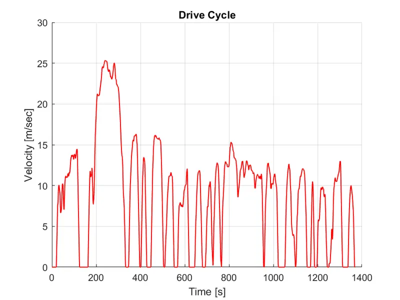
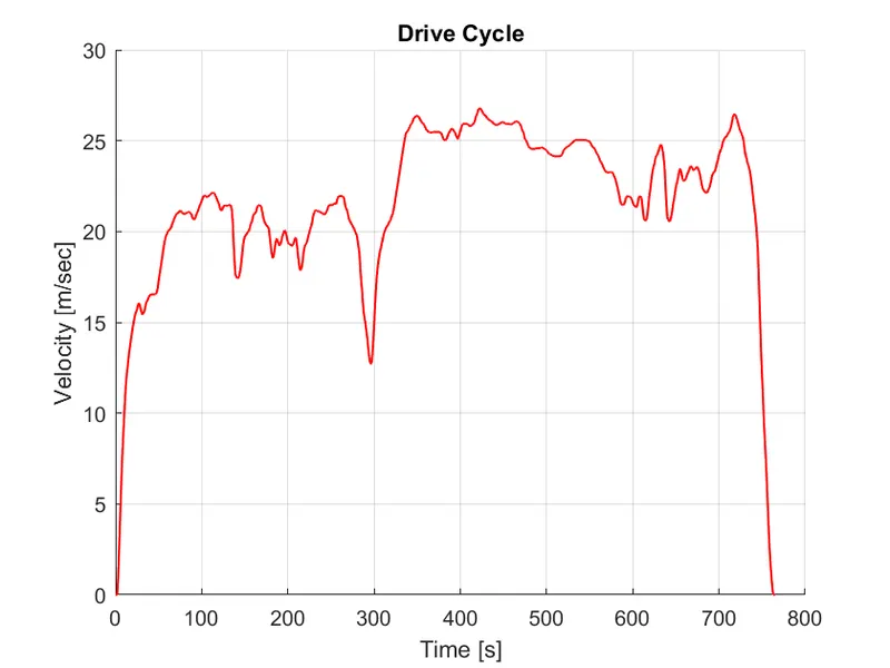
- Drive cycles
UDDS
HWFET
- Here we clearly seen in UDDS cycle the maximum speed is 25 m/sec ~= 90kmph and the cycle time is 1369 sec.
- In HWFET cycle the maximum speed is 27m/sec ~= 93 kmph and cycle time lies between 700- 800 sec.
- We see a greater number of fluctuations in UDDS cycle as compare to HWFET cycle
- Fuel economy numbers
UDDS
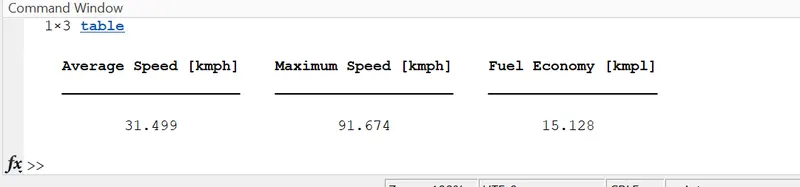
For conventional vehicle (15.128 kmpl)
For Hybrid vehicle (17.928 kmpl)
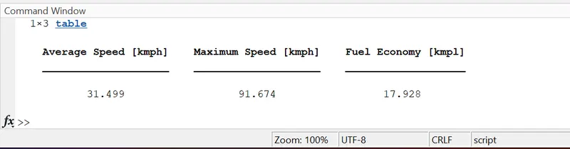
- At the starting engine is off and drive power provide by Electric Motor. In traffic (Fluctuation of velocity) Electric Motor drives the car. At ideal point vehicle is not consuming any energy.
- So, we can say that Fuel economy improves as the engine eliminates negative torque and negative power. This negative Torque revived with regeneration breaking
HWFET
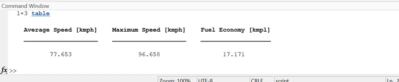
For conventional vehicle (17.171kmpl)
For Hybrid vehicle (20.971kmpl)
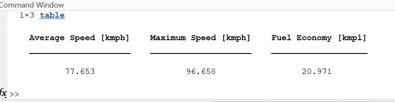
- Fuel efficiency improved more as the highway has less negative power as compare to urban drive. all the negative power will be regenerated with regen braking and the battery SOC will increase.
- The City Fuel Economy is much lower than the highway drive as the brake pedal engagement and idle time on the drive cycle is less.
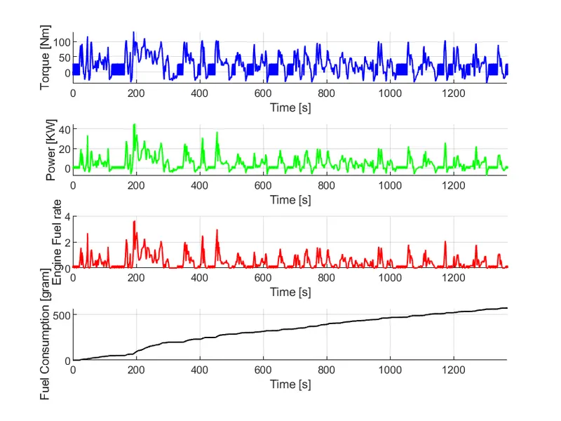
- Engine Torque, Engine Power, Fuel Rate, Fuel Consumption
UDDS
HWFET
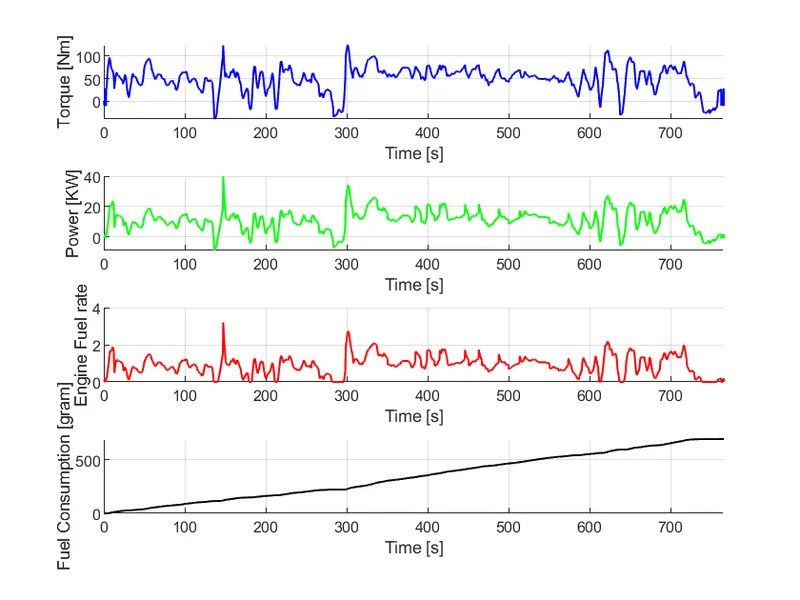
- The Power and torque requirements of the drive cycle are different, so the fuel flow rate varies and fuel consumption is calculated. We also observe the engine Torque, Engine Power and Engine Fuel rate Graph fluctuation more in Urban drive cycle as compare to Highway drive cycle
- The HWFET drive cycle has higher power and torque requirements and less negative torque and power.
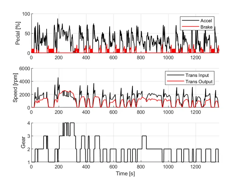
- Accelerator and brake pedal, gear command, input and output Speeds in RPM
UDDS
HWFET
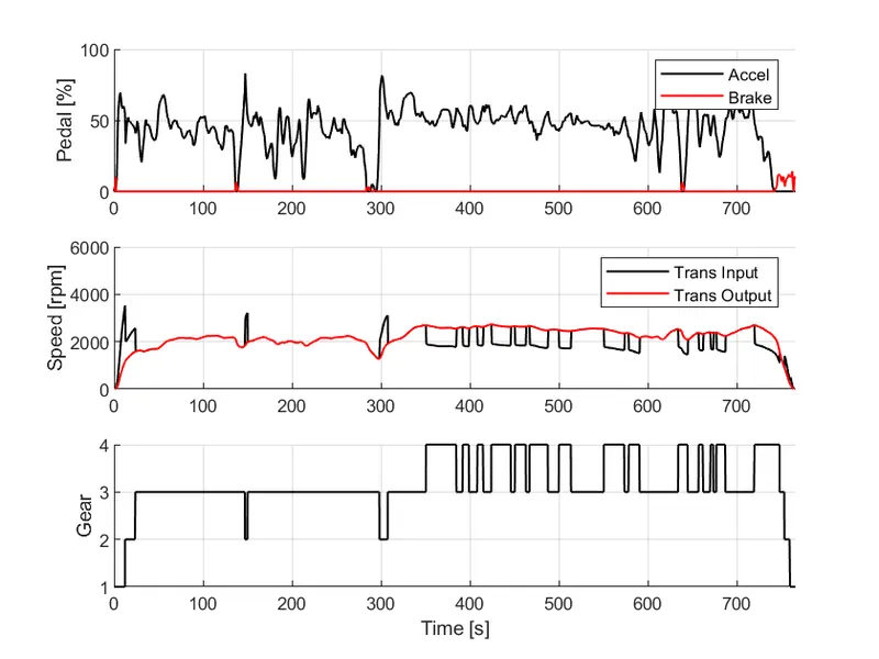
- Accelerator and brake pedals are used more in urban drive cycle because the drive cycle is not very smooth and also the gear shifted frequently.
- Brake requirements are lower in Highway drive cycle, more accelerator pedals are applied on the highway drive cycle, and gear shifts often occur because the drive cycle is smoother.
- Accelerator and brake pedal, the gear command of the transmission control unit, the required speed of the vehicle, the actual vehicle speed is plotted.
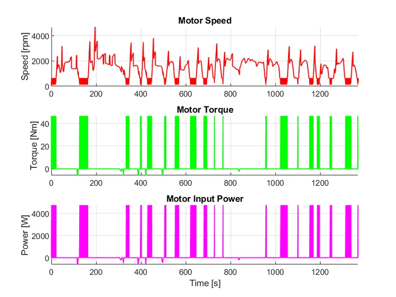
- Motor speed, torque, motor input power.
UDDS
HWFET
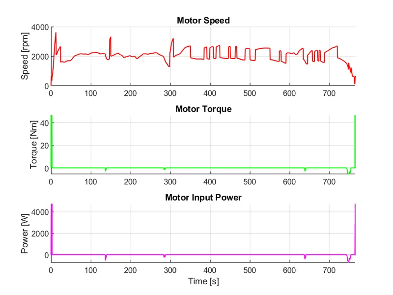
- Motor torque Drive the vehicle at starting, in the urban drive cycle frequent start and stops points is very high that’s why Electric Motor Torque requirement is too high as compare to Highway drive cycle.
- EM motor torque demand is low as the vehicle moves at high speeds and less idle on highway drive. Here most of the time vehicle drive on engine power.
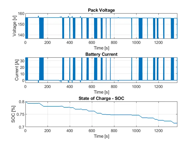
- ESS Pack voltage, current and SOC
UDDS
HWFET
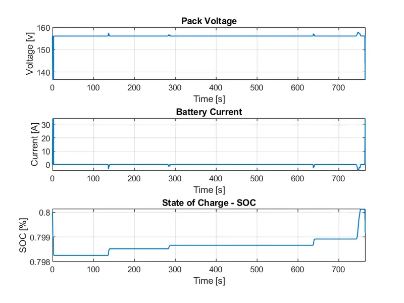
- The energy storage system (Battery) SOC is responding according to the Motor torque request and the Regen braking. If battery drive the motor and motor is drive the car the battery Voltage (pack voltage) and SOC decrease with time. And when we apply brake the battery store vehicle kinetic energy into battery potential energy and soc is also increase.
- Battery SOC increases on highway drive cycles due to less Electric Motor usage and regeneration braking is charged the battery.
- Engine operating points on the engine fuel map
UDDS
HWFET
- Motor operating points (motor input power map, with the motor max motoring and generating torque)
UDDS
HWFET
Electric motor operates between max motoring torque curve and max generating torque. Motoring Torque is used to drive the vehicle while the generating Torque is used to charge the battery. Here we plot Motor Torque with motor Rpm.
CONCLUSION
- Here we are able to Analyses and understands vehicle operating points based on engine and motor speed, torque, transmission speeds, pedal positions, gear, distance travelled, battery voltage, current, SOC etc.
- We are able to Post process calculations were performed and the required graphs were successfully plotted.
- Here we learn How improvement in the fuel efficiency numbers are done for the hybrid vehicle (kmpl) and we compared this data with conventional vehicle.
- We done all calculation for the Urban Cycle (UDDS) and Highway Cycle (HWFET).
- Therefore, the forward energy-based fuel consumption model of a P1 hybrid vehicle has been successfully Simulated using MATLAB and Simulink.
Reference:
Technical support engineer “Akash” .
**********************************************************************************************************************************************************************************************************************************************************************END