Week -2
CASE:1
AIM:- To make a simulink model of Door Bell using solenoid block.
OBJECTIVE:-
- To Create a situation where the switch is closed for 2 seconds and then released. Observe the physical movement of the plunger.
THEORY:-
- A solenoid is a type of electromagnet formed by a helical coil of wire whose length is substantially greater than its diameter, which generates a controlled magnetic field. The coil can produce a uniform magnetic field in a volume of space when an electric current is passed through it. The term solenoid was coined in 1823 by Andre-Marie Ampere.
-
The helical coil of a solenoid does not necessarily need to revolve around a straight-line axis,for example, William Sturgeon's electromagnet of 1824 consisted of a solenoid bent into a horseshoe shape (not unlike an arc spring).
- Solenoids provide magnetic focusing of electrons in vacuums, notably in television camera tubes such as vidicons and image orthicons. Electrons take helical paths within the magnetic field. These solenoids, focus coils, surround nearly the whole length of the tube.
- In engineering, the term "solenoid" refers not only to the electromagnet but to a complete apparatus providing an actuator that converts electrical energy to mechanical energy.
-
Obvious uses include door locking, in hotels, offices and secure areas, vending machines, remote access systems, turnstiles, car park and access barriers.
- use in Automation within automobiles- The most frequent use of a solenoid is an interlock device for integration into automatic gearbox drive selector. The function prevents the selection of “drive” without first receiving a release signal from the brake pedal, starting is only possible when parked.
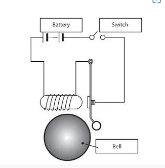
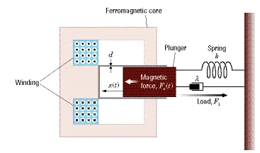
Basic components used to make a simple Doorbell
- Solenoid.
- A bell with plunger.
- Battery.
- Switch.
SIMULINK MODEL ( For Door Bell ):-
EXPANATION:-
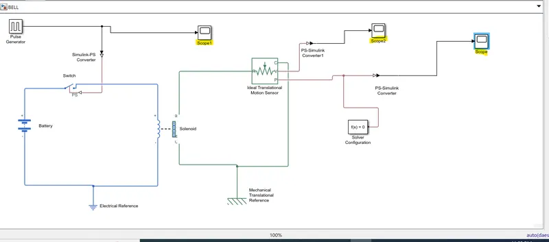
- First we select solenoid Block from library browser, and then we select Battery Block similarly from Library browser.
- Now we connect solenoid block with battery block via positive and negative terminal.
- A switch block is placed in between Solenoid block and battery block and it is connected with both the blocks. For the operation of switch we need to provide a physical signal through "Ps" port in the "Switch Block".
- Now, to provide physical signal for operating the switch. We use Pulse generator Block which generate a continuous square pulse.
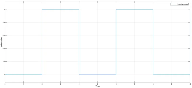
- Here we change some parameter for pulse generator (we set period value 4, Pulse width 50, Pulse delay 2 Sec and amplitude by default 1) it means initially the Pulse will be 0 for first 2 sec.
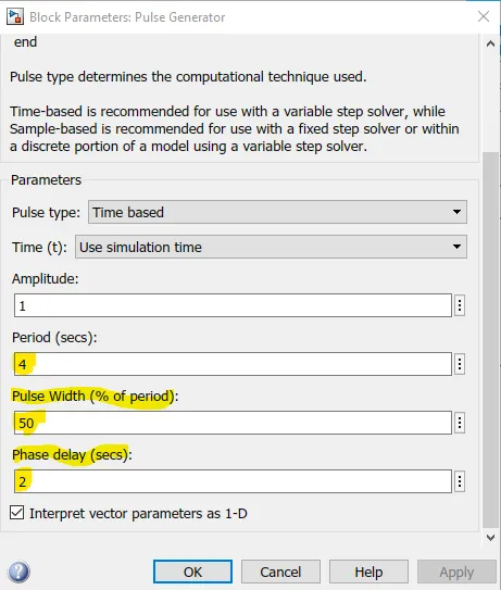
- For starting to end Pulse will take 4sec of time. For first 2 sec Pulse is 0 and for next 2 sec Pulse will be 1.
- Pulse that coming from Pulse generator Block is a Simulink value so we need to convert this value into Physical value for this we use "Simulink-PS converter" Block, since switch only takes physical values.
- When Amplitude is 1 the switch will be close and when Amplitude is 0 switch will be open.
- Now, we use Electrical reference Block which represents Earthing of the circuit. This Electrical reference Block must be connected through negative terminal of the battery.
- In solenoid we have R and C port, R represents plunger and C represent fixed point.
- Now, we connect R with "Ideal Translational Motion Sensor Block" (which senses the position of plunger) in the solenoid block.
- The Ideal Translation Motion Sensor Block has a output port V (for velocity of plunger ) and P (for position of plunger)
- Now we connect C port of Solenoid and C port of Ideal Translation Motion Sensor Block with “Mechanical Translational Reference” Block. Which represent fixed point.
- Now we connect both output port of Ideal Translation Motion sensor Block with "PS-Simulink converter Block". here physical value of (Ideal Translation Motion Sensor) block is converted into Simulink value.
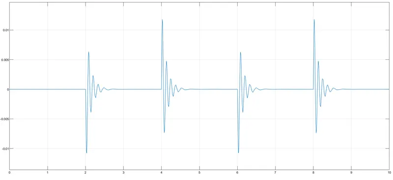
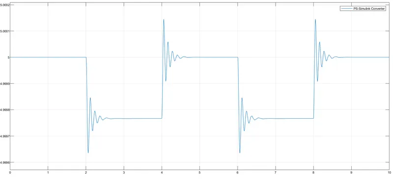
- Now, “PS-Simulink” converter Block is connected with Scope. Here we connected( two scope one with port V – scope and another with port P – Scope) and scope generated plot for position of plunger and velocity of plunger.
SCOPE RESULTS:-
- scope1 (pulse value)
- scope2( velocity of plunger)
- scope( Position of plunger)
*****************************************************************************************************************************************************
CASE:2
AIM:- To make a Simulink Model Using Thermistor to sense the tempearture of heater & turn on or turn off the fan.
OBJECTIVE:-
- Temperature source should be 20 °C from 0 to 10 seconds, 27 °C from 10 to 30 seconds, 23 °C from 30 to 50 seconds.Fan conditions should be ON if the temperature above 25 °C, OFF otherwise.
THEORY:-
- A thermistor is a type of thermal resistor whose resistance is strongly dependent on temperature, more so than in standard resistors. The word thermistor is a portmanteau of thermal and resistor.
- Thermistors are divided based on their conduction model. Negative Temperature Coefficient (NTC) thermistors have less resistance at higher temperatures, while Positive Temperature Coefficient (PTC) thermistors have more resistance at higher temperatures. Hence, a PTC thermistor's resistance is directly proportional to temperature.
- NTC thermistor are widely used as inrush current limiters, temperature sensors, while PTC thermistors are used as self-resetting overcurrent protectors, and self-regulating heating elements. An operational temperature range of a thermistor is dependent on the probe type and is typically between −100 ⁰C and 300 ⁰C (−148 °F and 572 °F).
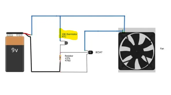
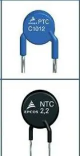
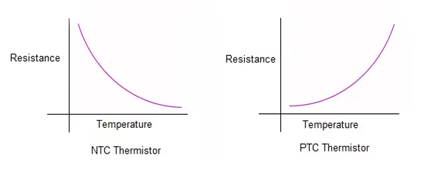
figure:1 (simple cooling fan circuit having Battery, Thermistor, Fan, Transistor, Resistor) || figure:2 (Types- PTC & NTC) || figure:3 (Resistance Vs Temperature) ||
Depending on materials used, thermistors are classified into two types:
- NTC thermistors, resistance decreases as temperature rises; usually due to an increase in conduction electrons bumped up by thermal agitation from the valence band. An NTC is commonly used as a temperature sensor, or in series with a circuit as an inrush current limiter.
- PTC thermistors, resistance increases as temperature rises; usually due to increased thermal lattice agitations particularly those of impurities and imperfections. PTC thermistors are commonly installed in series with a circuit, and used to protect against overcurrent conditions, as resettable fuses.
SIMULINK MODEL:- ( Fan Operations using THERMISTOR )
ExPLANATION:-
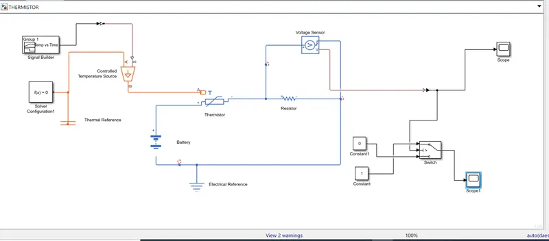
- A "Thermistor Block" is taken form Library browser in the Model, and a "Battery Block" is also taken and connect them ( +ve with +ve and -ve with -ve ) now we take "Resistor Block" and connected with "Thermistor Block" (+ve terminal of Thermistor is connected with –ve terminal of Resistor).
- Now, an "Electrical Reference Block" is connected near the negative terminal of the "Battery Block" which represents the earthing of actual circuit.
- Now, we use "Voltage sensor Block" in place of voltmeter, and connect in the circuit parallel to the "Resistor Block" after that we need some physical quantity as input signal for Thermistor.
- We use "Controlled Temperature Source Block" one port of this block is connected to "Thermal reference Block" that is port A and another port is connected to "Signal builder Block" with the help of "Simulink-PS converter Block". In "Signal builder Block" we create an input signal for system as per given condition.
- In [0-10] sec – Temperature is 20 Degree Celsius (293.15K)
- In [10-30] sec – Temperature is 27 Degree Celsius (300.15K)
- In [30-50] sec – Temperature is 23 Degree Celsius (296.15K)
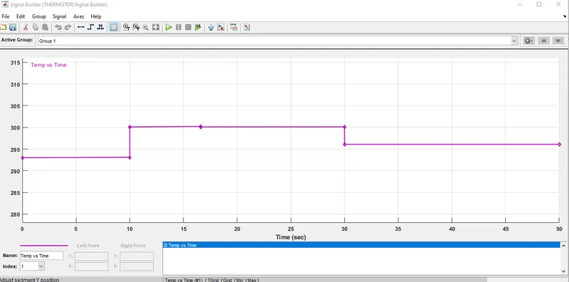
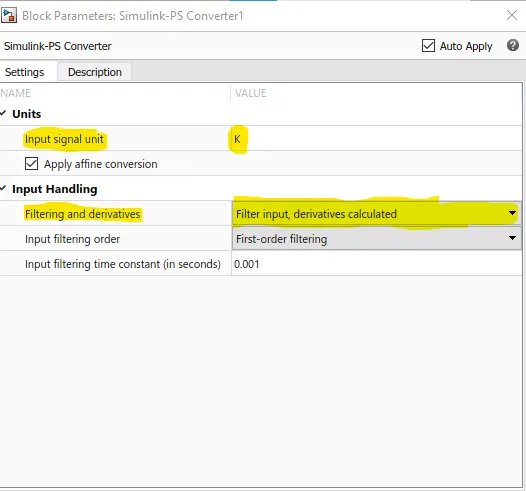
- Here the Temperature is converted in Kelvin and also selected solver requires input derivatives, in "Simulink-PS converter".
- The output of "Voltage sensor Block" is connected to "Scope" with the help of "PS-Simulink converter" ( to convert Physical value to Simulink value).
- After run the simulation and double click on the "Scope Block" we will get..
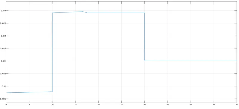
Scope 1 result
- We observe that from graph How Voltage is changing with time. In [0-10sec] when Temperature is 293K Voltage is in between [0.0095-0.01], and from [10-30sec] when Temperature is 300K Voltage is in between [0.0125-0.013], and from [30-50sec] when Temperature is 296K Voltage is approx. 0.011.
- Fan should be "ON" when Temperature is More than 25 Degree Celsius, from above graph we can observe when Voltage is more than 0.0125 Fan should be "ON" and when Voltage is below 0.0125, Fan Should be "OFF".
- To follow above logic we use "Switch Block" which is connected to "Voltage sensor Block" with the help of "PS-Simulink converter".
- The top port of "Switch Block" is connected to a "Constant Block" of value 1 and bottom port of the Switch Block is connected to another "Constant Block" of value 0.
- The Middle port of the "Switch Block" is conditional input port, it means when the Voltage value is greater than threshold value then "Switch Block"pass the value 1 and when Voltage is less than threshold value it pass the value 0.
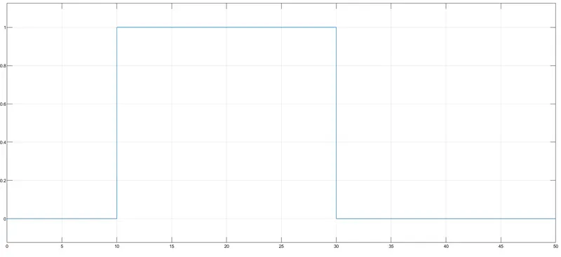
scope 2 RESULT
- By double clicking the scope block we can observe the graph as mentioned above.
FINAL CONCLUSION:-
- Here we run both the model (CASE: 1 and CASE: 2) and presented the report.
- We learn how to use of block to make a MODEL, how to edit the block as per our need or system demand.
- We learn how to configure pulse generator and signal building block.
************************************************************************************************************************************************************************************************************************************************************************************************************************ END..............