Assignment 7-Side Pole Crash Simulation Challenge
AIM: To perform side pole crash simulation with the given BIW frame and request for Time History plots.
OBJECTIVE:
The Objective is to simulate for the following problem statements.
- Sectional force in the cross member.
- Intrusion at B pillar, hinge pillar and fuel tank region.
- Peak velocity of an inner node of the door.
THEORY:
- A side pole car crash is a type of car accident that occurs when a vehicle collides with a pole or a tree on its side. This type of collision can be particularly dangerous because the pole or tree can penetrate the car's cabin, potentially causing serious injuries or even fatalities to the occupants.
- Side pole car crashes can happen for a variety of reasons, including driver error, weather conditions, or road design. In some cases, the design of the vehicle itself can play a role in the severity of the crash.
- To reduce the risk of injury or death in a side pole car crash, it is important for occupants to wear their seatbelts and for the vehicle to have appropriate safety features, such as airbags, crumple zones, and reinforced side pillars. Additionally, road safety measures such as guardrails and properly placed utility poles can help to prevent these types of crashes from occurring in the first place.

SAFTEY STANDARDS
Several safety standards have been developed to address side pole car crashes and improve the safety of vehicles in such accidents. Here are some of the key standards:
- Side Impact Protection: Most modern cars are designed with side-impact protection features, such as side airbags, that help to protect occupants in the event of a side pole car crash. The National Highway Traffic Safety Administration (NHTSA) in the US requires all new cars to meet certain standards for side-impact protection.
- Roof Crush Resistance: The strength of a car's roof is crucial in preventing the roof from collapsing in a side pole car crash. The Federal Motor Vehicle Safety Standard 216 (FMVSS 216) in the US specifies minimum requirements for roof strength.
- Side Pole Test: Many vehicle safety ratings organizations, such as the Insurance Institute for Highway Safety (IIHS), conduct side pole tests to evaluate a vehicle's performance in such a crash scenario. This test simulates a car striking a pole or tree at an angle of 75 degrees at a speed of 20 mph.
- Side Impact Test: Another important safety standard is the side impact test, which evaluates a vehicle's performance in a side collision. The NHTSA and IIHS both conduct side impact tests to assess a vehicle's crashworthiness.
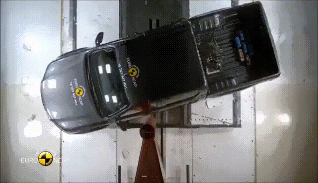
Overall, these safety standards are designed to ensure that vehicles are equipped with the necessary safety features and structural strength to protect occupants in the event of a side pole car crash. It is important for consumers to look for vehicles that meet these standards when shopping for a new car.
PROCEDURE/STEPS: -
- Import the model
Very first we Import the ".rad" starter file of the model, "neon_side_reduced_0000.rad" in Radioss using Import Solver Deck option.
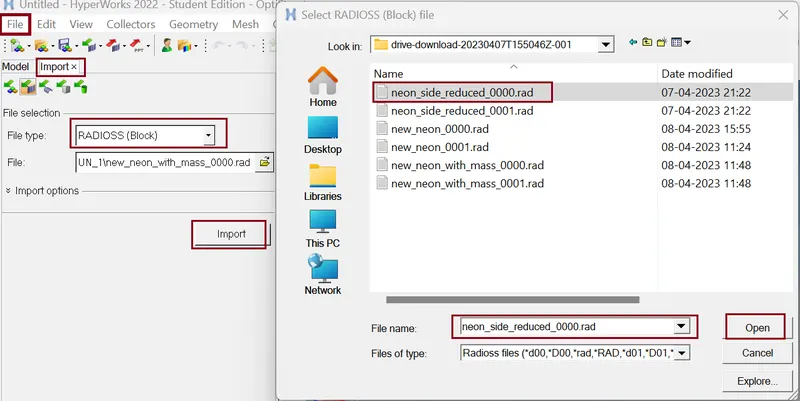
Our model is open in Hyper Mesh GUI
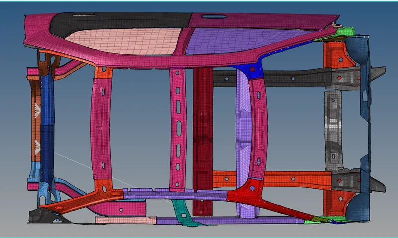
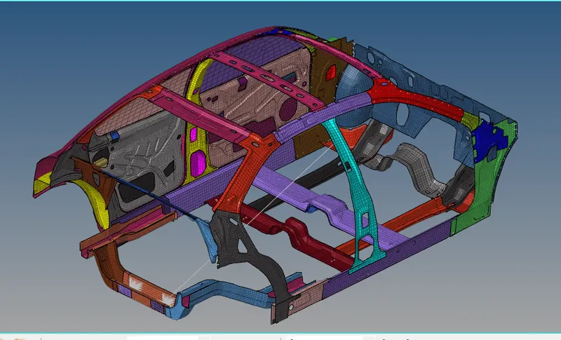
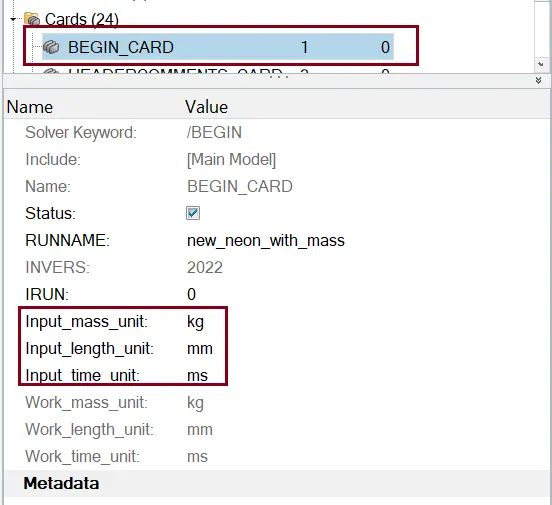
- Checking for unit system
Command: Model >> Cards >> BEGIN_CARD
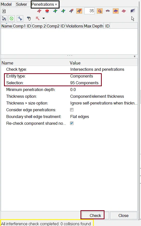
- Checking for Penetration and intersection
Command: Tools >> Penetration check >> Edit the card as per figure below.
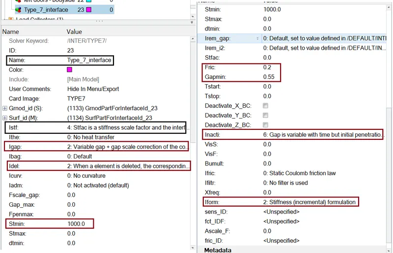
- Create appropriate interface
Here we use Type-7 Node to surface contact for Both the Slave nodes and the Master nodes.
- Correct rigid bodies if any issues
As there is no penetrations and intersections there is no need of rigid bodies.
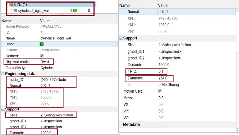
- Create rigid wall with friction 0.1
Here we need to create a cylindrical rigid wall at the left side of the car, we will need the outermost node at the front left door of the car. So we will create the outermost node on the element edge using temp nodes option.
Command: Solver Deck >> Right click >> Rwall >> CYL
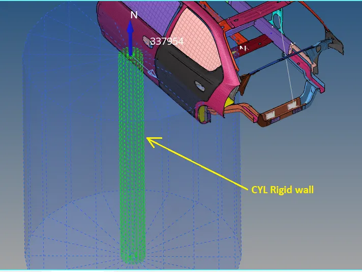
- Reach the target weight of 700 kg and Balancing COG
The BIW model doesn't consist of the exact weight of the vehicle so Additional mass should be added to the BIW model considering the weight of the Body after manufactures e.g. with the weight of the seats, the weight of the persons and all other weights in realistic condition.
The targeted weight is given 700kg where the actual mass before adding external weight is 166kg.
For mass balancing we use Hyper crash application and import the model in Hyper crash GUI.
Edit the tab as figure below..
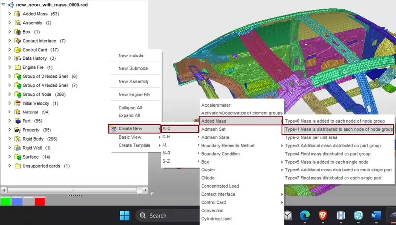
And distribute the mass (700 – 166 = 534 kg) in the car body
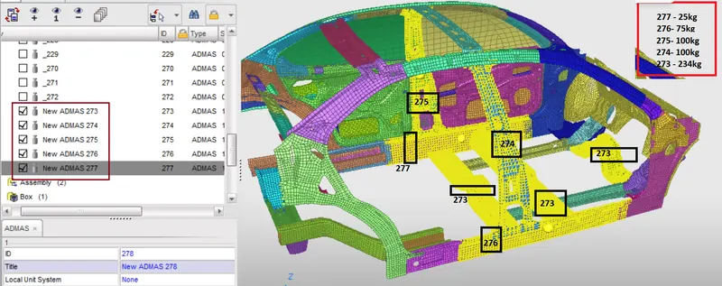
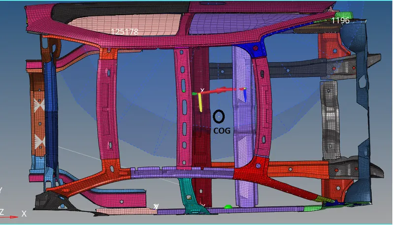
After that import the same model in Hyper Mesh and check Mass and cog
For this we use Command: Tools >> mass Details >> mass, cog and inertia
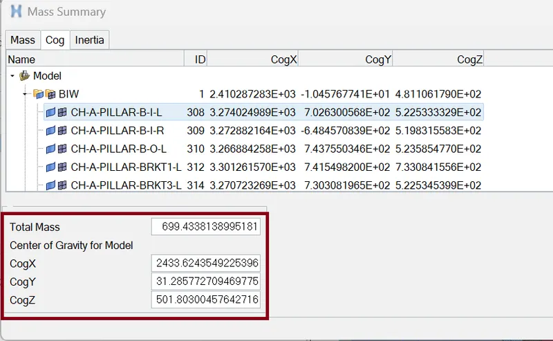
Current COG location
- Applying initial velocity
solver >> create >> boundary conditions >> INIVEL
- Initial velocity 20 mph.
- Converting 20mph into mm/ms
- 1mph = 0.447 mm/ms
- So, 20mph = 8.94 mm/ms
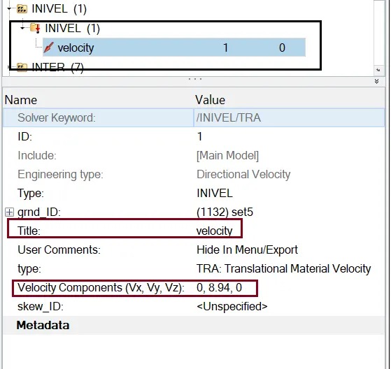
Define the Node group on which specified initial velocities are applied (grnd_ID1). For our simulation, we will be selecting the whole vehicle setup.
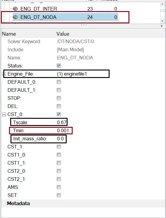
- Creating Time-step (0.5 to 0.1 microseconds)
We use command :Solver >> ENGINE_KEYWORDS >> DT/NODA
- Simulation Run time
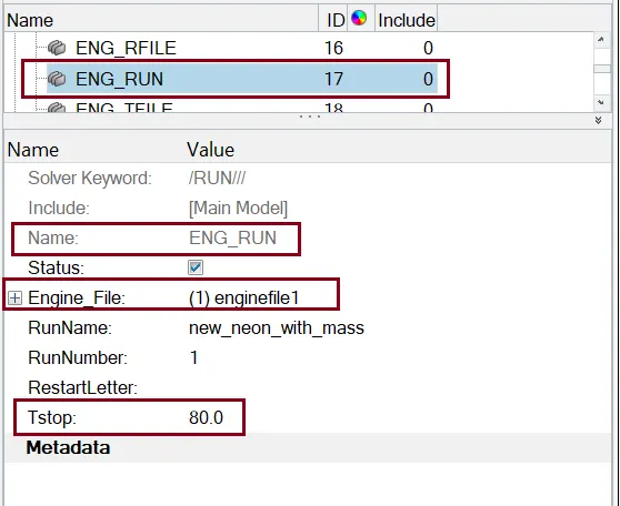
- 80 ms
Goto Model browser >> Cards >> Eng_Run >> Tstop = 80.
- Creating Cross Section
The results which we want on required cross sectional parts will be calculated based on a frame of reference. So before creating cross section, we will create moving frames on a particular node of that section. Now as we have to create the moving frames which are also called as local axis, we have to perfectly align our local axis to the global axis.
For creating Moving FRAME we use solver >> right click >> create >> FRAME >> MOV select the three node as given below and hit create.
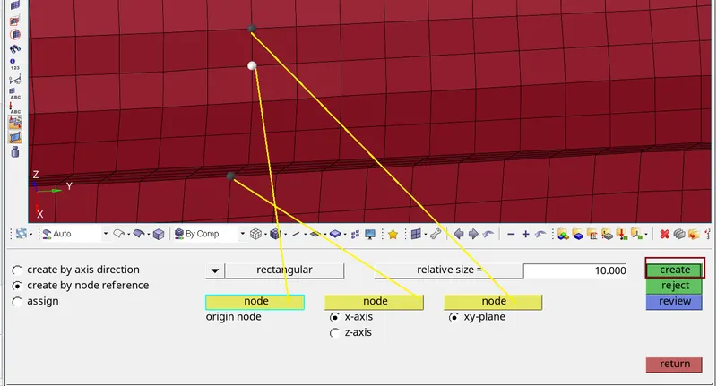
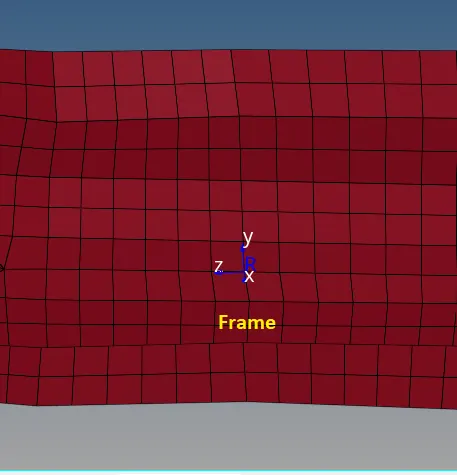
For creating Section, we use solver >> right click >> create >> SECT. select the N1, N2 and N3 in similar way as previous.
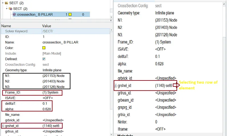
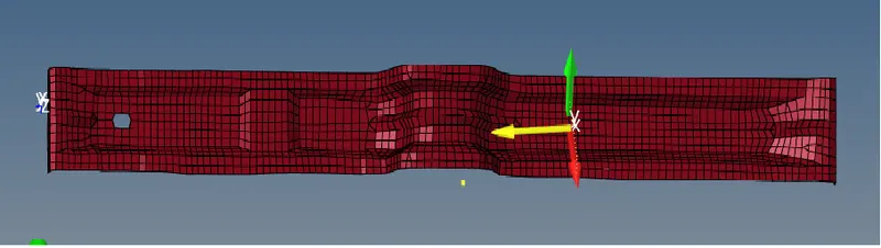
Similarly, we create other section
- Intrusion at B pillar, hinge pillar and fuel tank region
Steps
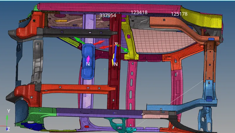
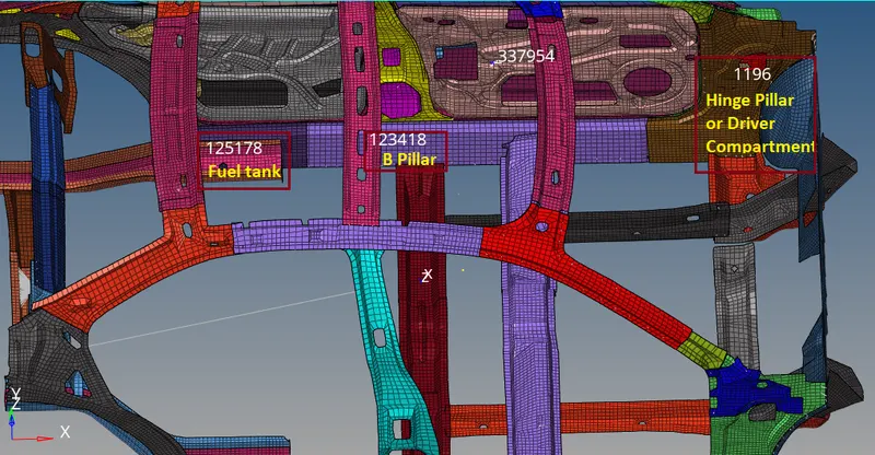
- Highlight the node at B pillar, hinge pillar and fuel tank region
- Create a moving skew on exact opposite frame
solver >> right click >> create >> skew >> MOV select the three node.
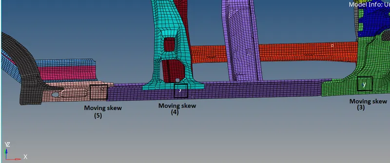
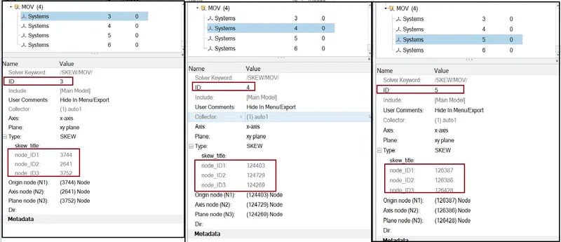
- Measure the distance between highlighted nodes and skew.
Distance between node “1196” (Hinge Pillar) to skew 1st or skew ID (3)
Distance between node “123418” (B Pillar) to skew 2nd or skew ID (4)
Distance between node “125178” (Tank region) to skew 3rd or skew ID (5)
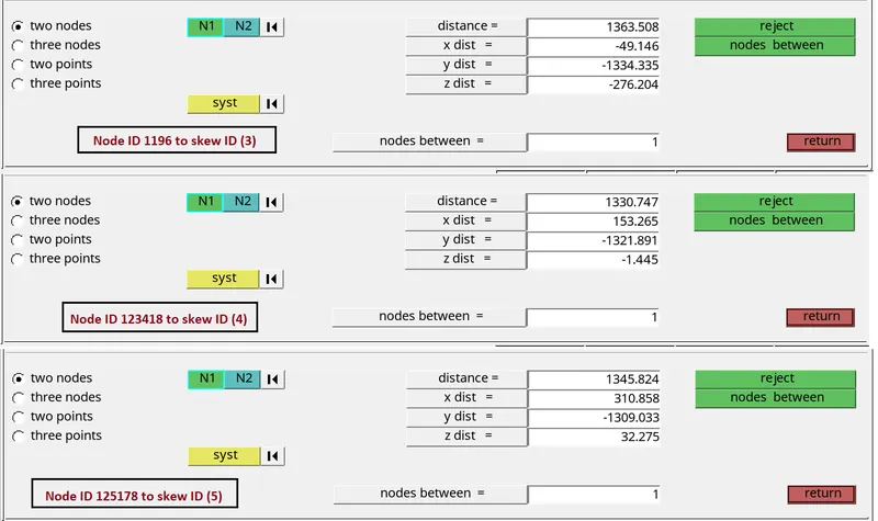
In intrusion output displacement we need to subtract this distance value.
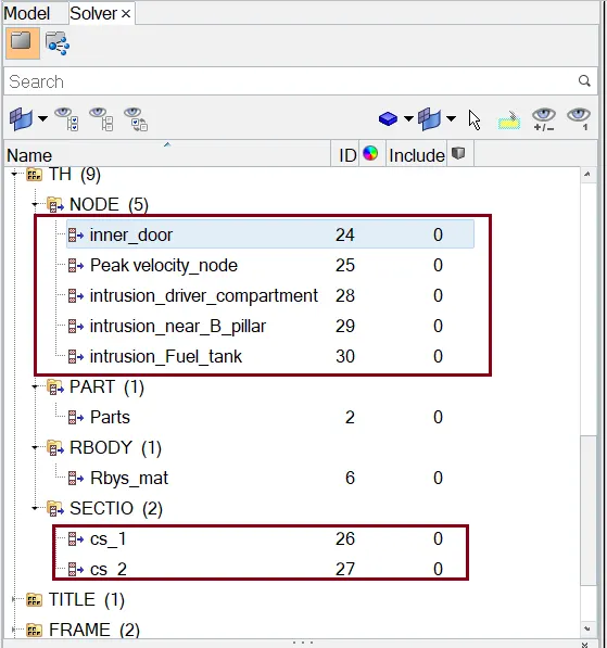
- Requesting TH (time history files) for sectional force, intrusion and peak velocity node
- CHECKS:
Here we need to delete the unwanted data in the model.
The Model checker will give us any warnings and Errors regarding the model definition and, the boundary and Kinematic conditions, etc.
Command: Tools >> Model Checker >> Radioss Block >> right click >> Run
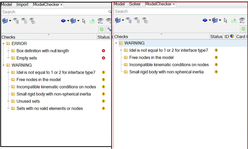
All error are fixed by auto fix option.
RUN THE ANALYSIS:
Analysis >> Radioss >> Input File: (File Location) >> Hit Radioss
The input file is the same Started file (contains model information) that we had just imported.
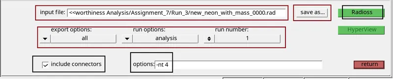
After 2.5 hrs our simulation is completed. it will show JOB IS COMPLETED.
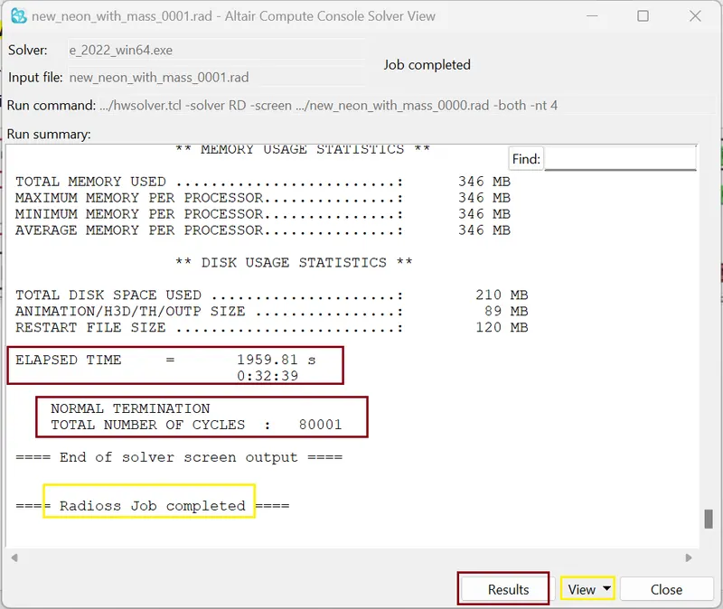
- Checking energy error and mass error:
we need to check the output of simulation in 0001.out file
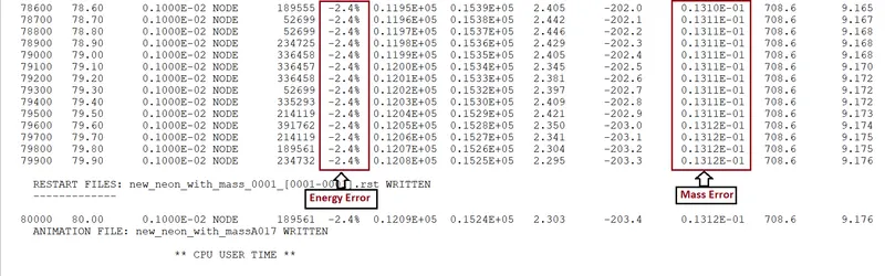
Here we have Energy Error -2.4% and mass error is 0.01312.
- Condition for acceptable result
- The error {Energy} must be less than – 15 % at the end of computation (0% for a good model setup).
- The error {mass} must be less than 2%.
So, from output data our both the condition is satisfy we go for plots.
RESULTS
- Energy Graphs:
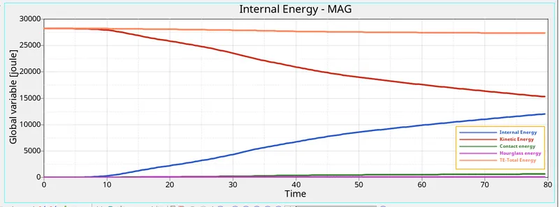
The changes in kinetic and internal energies occur at the exact moment the BIW makes contact with the rigid cylindrical wall. Understandably, the BIW loses kinetic energy throughout the simulation due to the obvious decrease in velocity. At the same time, it absorbs the forces, and this results in an increase in internal energies, and as a result, the deformations also occur.
SECTIONAL FORCES:
1.) Sectional force in the cross member (Section 2)
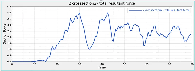
The maximum value of Force is 4.011kN at 42.500 ms (mili seconds)
2.) Sectional force in the cross member (Section 1 near B Pillar)
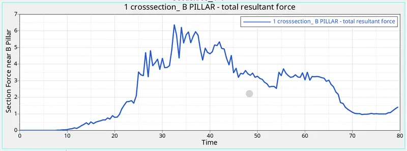
Here we get the maximum Force is 6.66kN at 32.500ms (mili seconds)
We also observe the point of impact is near to B Pillar so, we get Maximum Force in section 1 as compare to section 2.
Comments:
Cross-members are very crucial in the side-impact analysis as these components prevent the body to shrink or deform inward. When the car hits the rigid body maximum number of forces will pass through the cross member of the base and roof. This component along with door bar and support, door outer, B pillar, and rocker are also involved in the majority to prevent deforming. But the forces acting on every other component eventually pass from the cross member.
INTRUSION
1.) Driver Compartment
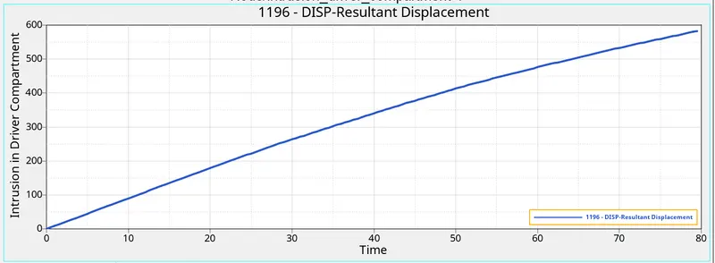
Here from plots, we get maximum intrusion is 582.8331mm.
But I know the distance between node and Skew is 1363.508 mm
So, Effective intrusion in the Driver Compartment is (1363.508 – 582.8331 = 780.6749mm)
2.) Near B Pillar
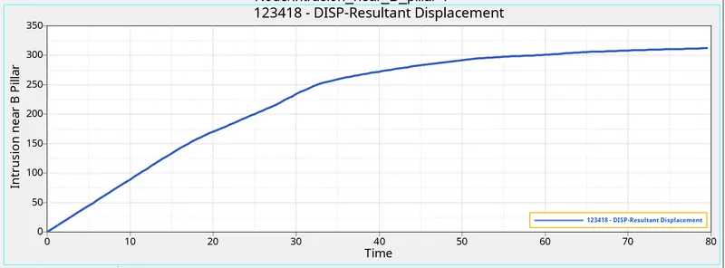
Here from plots, we get maximum intrusion is 312.177mm.
But I know the distance between node and Skew is 1330.747 mm
So, Effective intrusion near B Pillar Compartment is (1330.747 – 312.177 = 1018.57mm)
3.) Near Fuel Tank
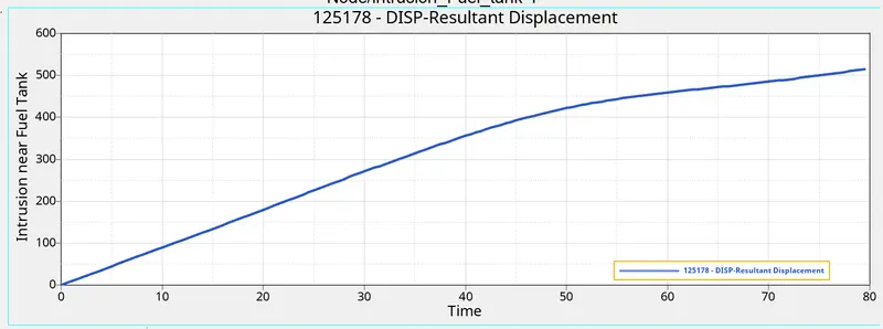
Here from plots, we get maximum intrusion is 515.087 mm.
But I know the distance between node and Skew is 1354.824 mm
So, Effective intrusion near Fuel Tank Compartment is (1354.824 – 515.087 = 839.737mm).
- Peak velocity at Inner Door:

As we all know that when the car hits the pole first impact will be the door and due to the deformation, the inner portion of the door might hit the passengers inside the car and lead to injuries. Hence it is important that the Peak velocity at the door region is to be calculated.
From the Graph, the peak velocity of the node on the door is 10.5760 mm/ms at 12 ms. The velocity of the node is almost constant before hitting the rigid cylindrical wall (up to 7 ms). After impact, there is a steep drop and then a small rise, probably due to the folding deformation created as the crash progressed (due to inertia). As time passes, we can see the velocity gradually decreasing (at the 77.5ms we get minimum velocity 0.075 mm/ms).
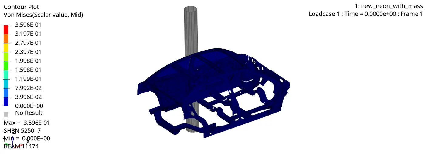
VON-MISES STRESS
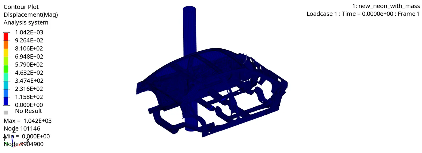
DISPLACEMENT
CONCLUSION:
Here we done the Side crash analysis on the given BIW model of the Dodge Neon as per requirements. The output requests were also generated after the creation of cross-sections in each of those regions. Peak velocity and intrusion values were also measured at certain points of the model.
Fuel tank intrusion and intrusions, in general, could be reduced by using anti-intrusion beams (or side-impact beams) between the pillars.
LEARNING OUTCOME:
- How to change the COG position.
- How to check for the penetrations and intersections.
- How to create the interfaces and how to find connectivity, to check whether the free parts exist in the component.
- How to give Peak Velocity of an inner node of the door.
- How to assign the initial velocity.
- How to obtain intrusions.
- How to create a rigid pole.
- How to request For outputs.
***************************************************************************************************************************************************************************************************************************************************************************END
Thanks & regards,
DEVESH KASHYAP