Week 6 - Creating connection for Rear door
AIM:- To perform the connections on the rear door (Model), By using different connections techniques.
OBJECTIVE:-
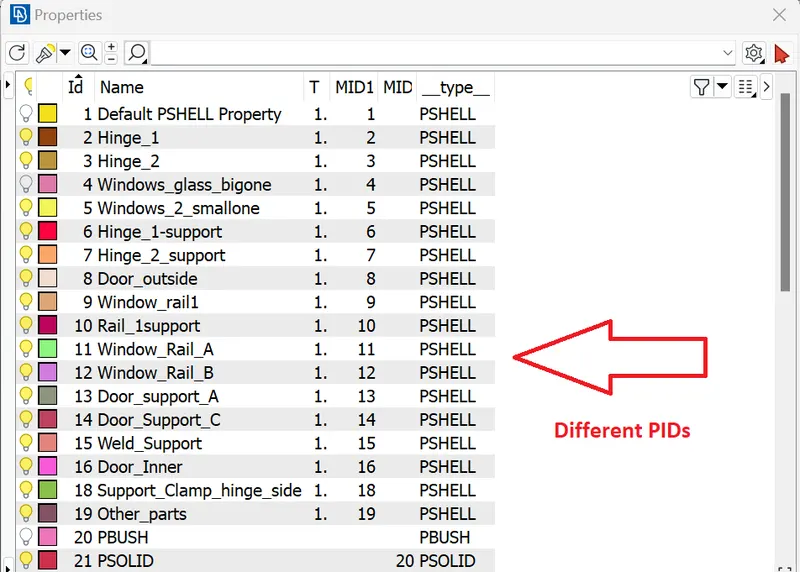
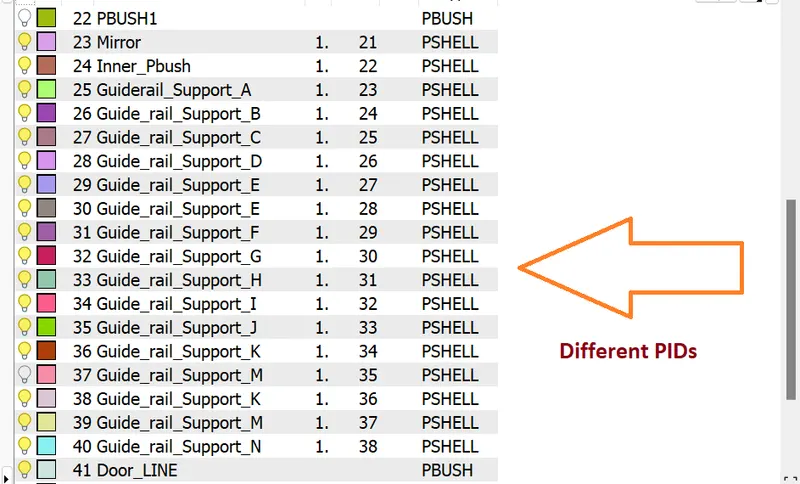
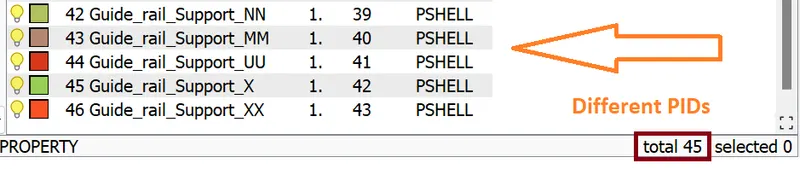
- To Create different PIDs for different components.
- To Perform suitable connections.
PROCEDURE/STEPS:
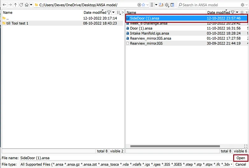
- Importing the CAD model
Command: File >> Open >> SideDoor(1).ansa
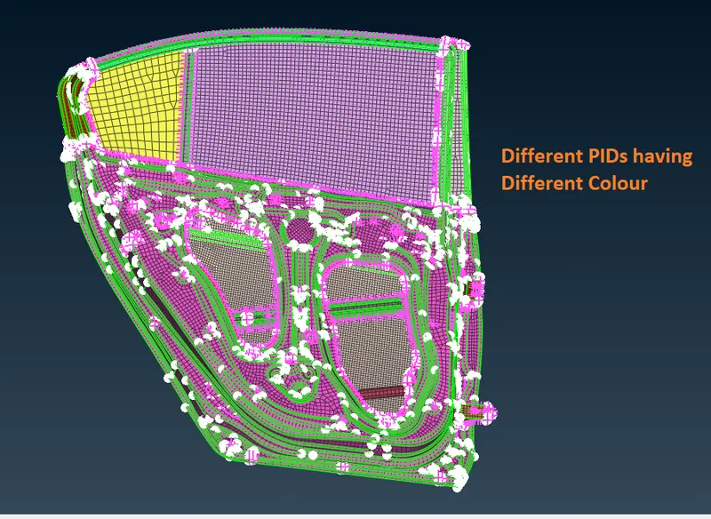
- Creating different PIDs
Command: Classic MESH >> Macros >> SetPIDs >> Macro (Feature Selection) >> Select Part (left click for selection and using Boolean operator) >> hit middle mouse click >> New >> PSHELL >> Name ……. >> ok.
- Connection
- RBE2 Connection
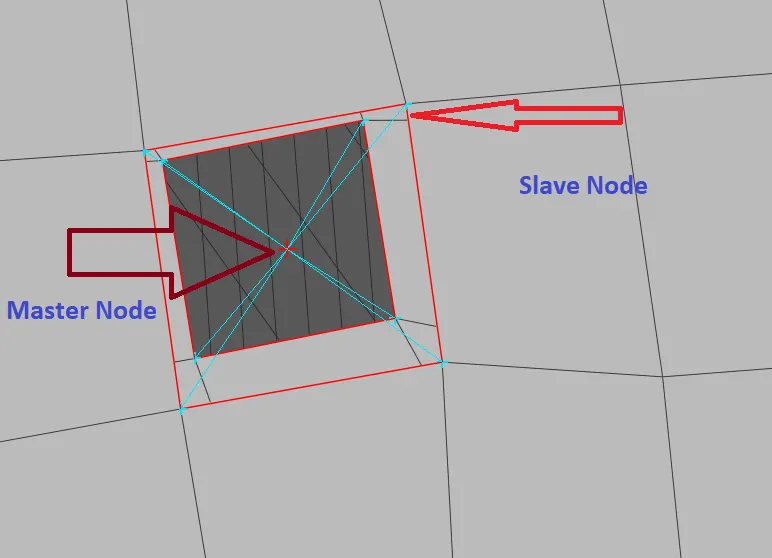
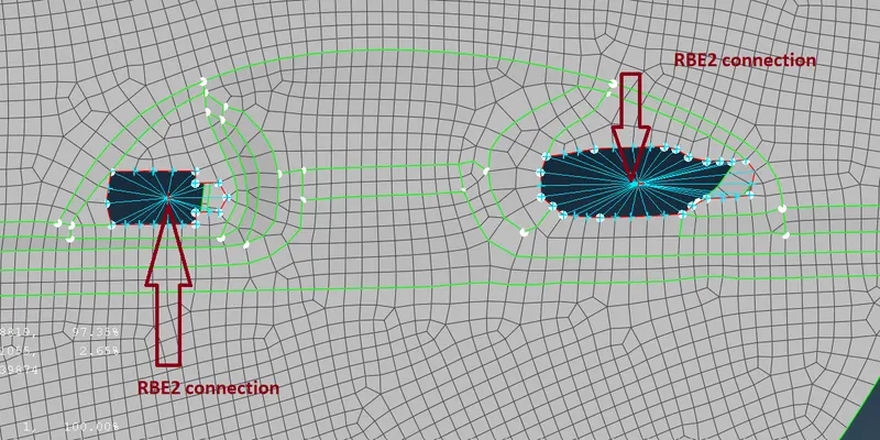
RBE2 type connection are rigid connection (it means all 6 degrees of freedom are restricted). Any rigid type of connection having two Nodes Master Nodes (Independent Nodes) and Slave Nodes (Dependent Nodes). Dependent Nodes behaves as per Independent Nodes.
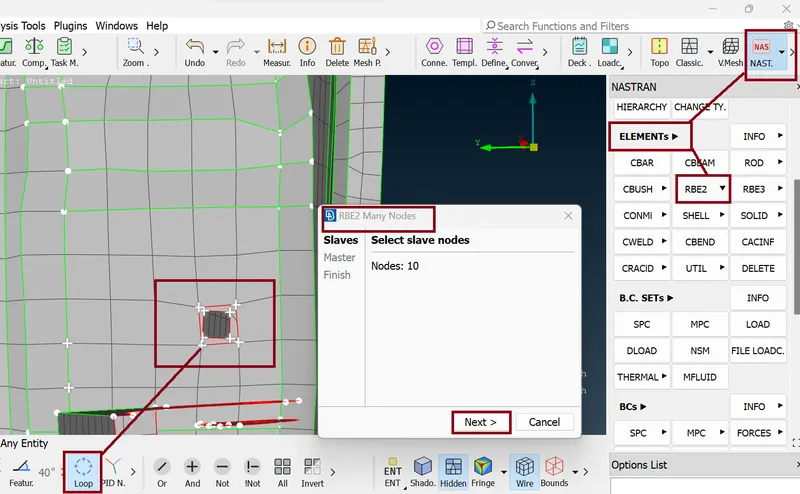
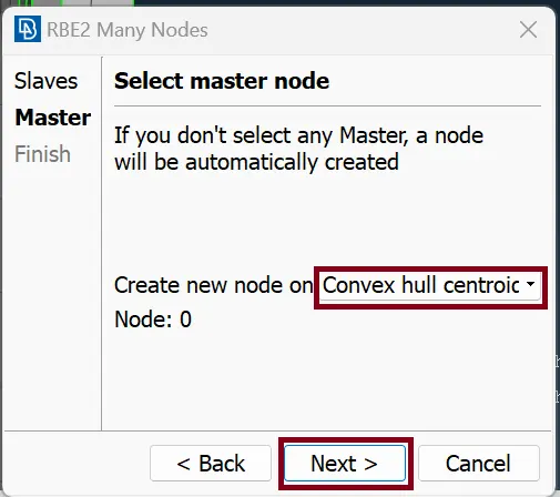
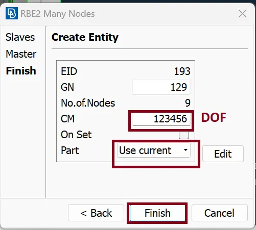
Command: NASTRAN >> ELEMENTs >> RBE2 >> Many Nodes >> selecting Slave Nodes ( Nodes on the Edges of the hole ) and Switch on the Loop button (Feature Selection) >> Next >> Convex null Centroid >> Next >> create Entity >> Next
Finally we create RBE2 connection which is shown in below
- Bolt Connection:
Command : Topo >> Points >> On COG >> switch on the LooP >> Select the Edge >> hit middle mouse click.
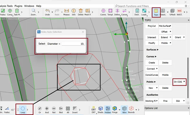
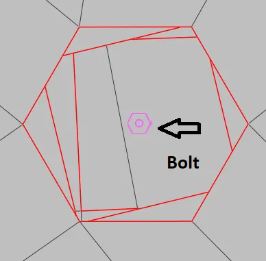
Now COG is created we need to convert this COG into Bolt. for this we use command : Assembly >> Convert >>3D Points >> Selecting COG points >> hit middle mouse click >> Select Bolt option >> ok.
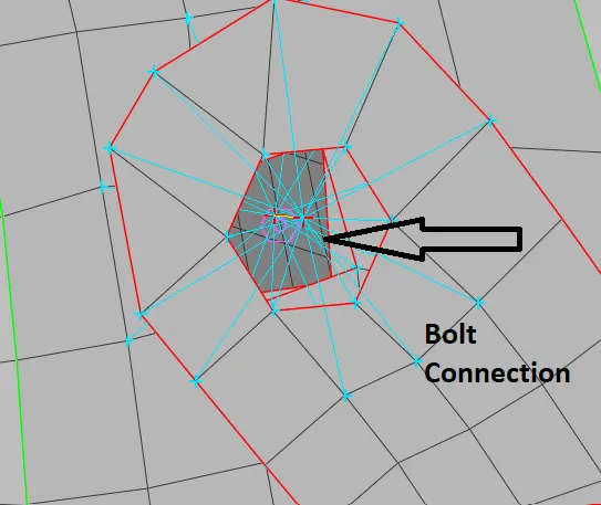
Now for the Bolt connection we Go : Assembly >> Connection Manager >> Selecting Bolt >> Hit Middle Mouse click >> selecting P1,P2,P3 and P4 as per requirement >> hit middle mouse click >> Edit connection Manager as per figure given below.
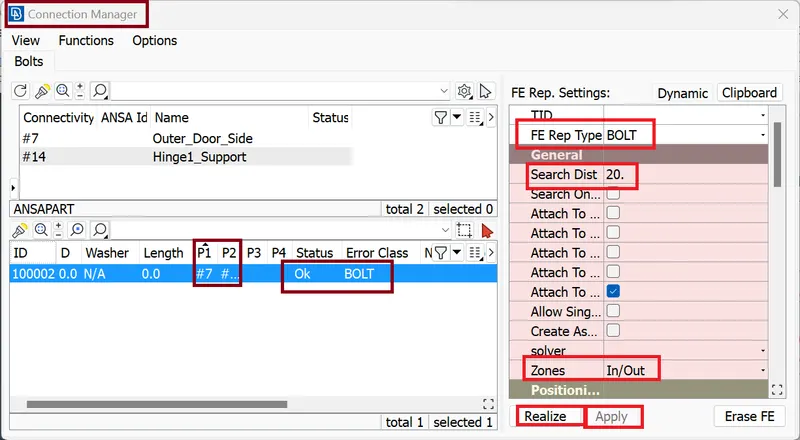
Finally we have Bolt connection
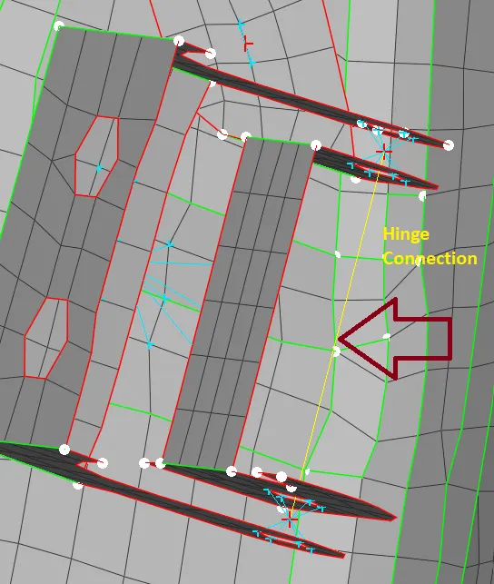
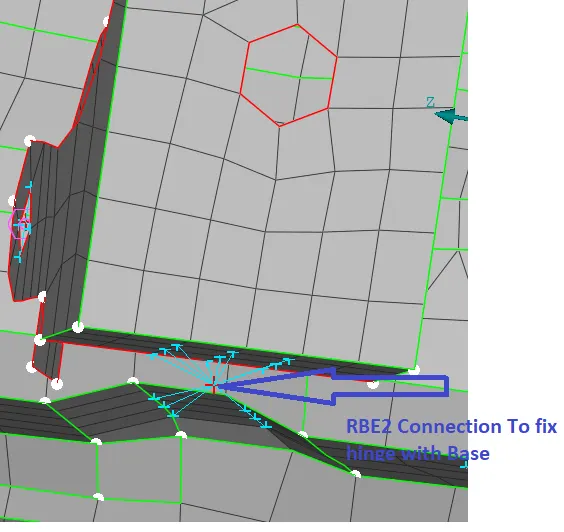
- Hinge Connection: - Hinge need to be rotate in one direction so we need to restricted hinge connection in 5 directions.
Command: NASTRAN (deck) >> ELEMENTs >> RBE2 >> Two Nodes >> selecting Master Node of these two RBE2 connection.
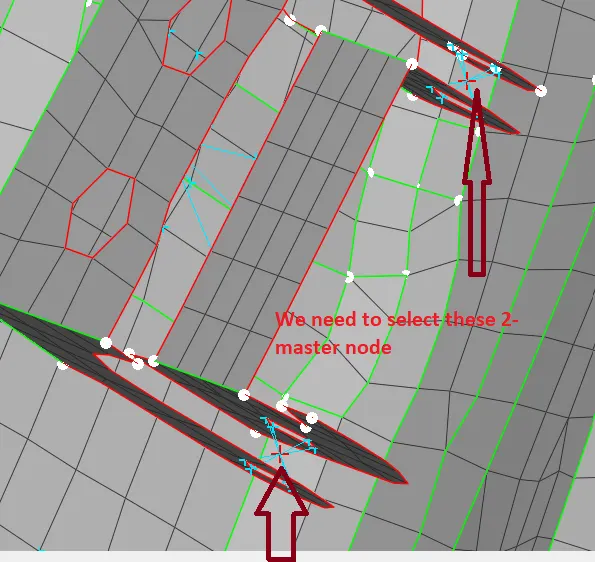
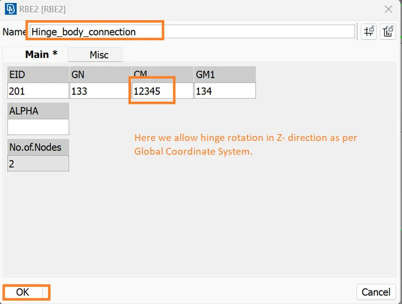
Finally we get Hinge Connection
- Spotweld Connection:
Command: Topo >> Points >> On COG >> switch on the LooP >> Select the Edge of the Element >> hit middle mouse click.
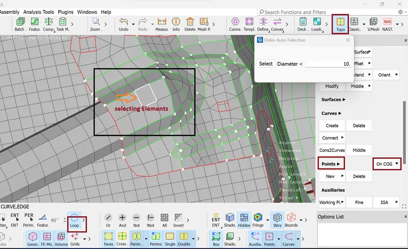
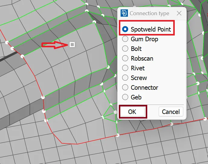
Now COG is created we need to convert this COG into Spot weld. for this we use command: Assembly >> Convert >>3D Points >> Selecting COG points >> hit middle mouse click >> Select Spotweld Point option >> ok.
Now for the Spot weld connection we Go : Assembly >> Connection Manager >> Selecting Spot weld >> Hit Middle Mouse click >> selecting P1 and P2 >> hit middle mouse click >> Edit connection Manager as per figure given below.
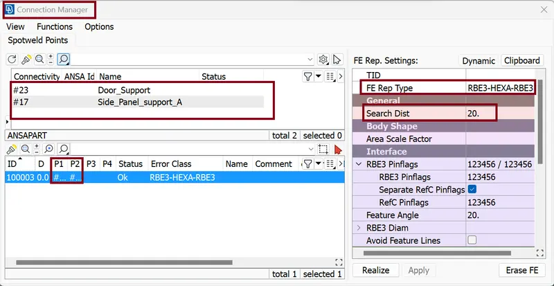
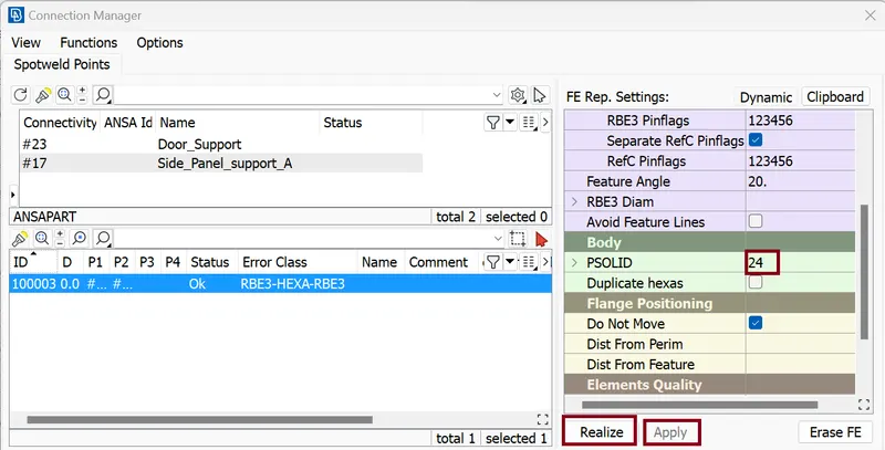
Here we create PSOLID card ID which represent solid connection.
Finally, we have Spot weld connection
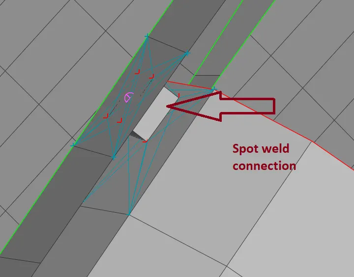
- Door_Handle Connection:-
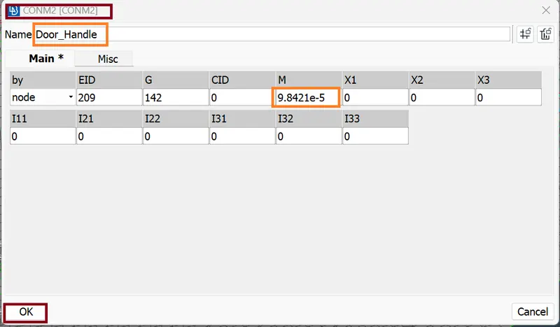
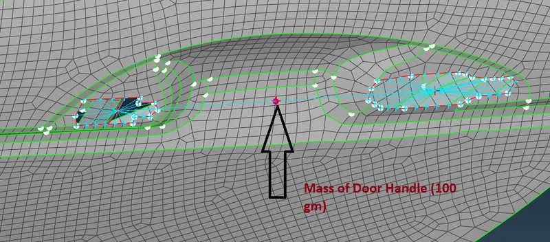
The Door Handle Connection is a type of RBE2 connection. Here we add a point mass by using the CONMi option present in the elements deck. Select CONM2 and pick the necessary node to add the masses. It is to be noted that mass has to be entered in tonnes. The realized connection is shown in the figure below.
Command: NASTRAN (deck) >> ELEMENTs >> RBE2 >> Many Nodes >> Switch ON Loop (Feature section) >> Next >> Convex hull centroid >> part use current >> Finish.
Now for Handle we need to assign some mass (Aprox.. 100gm) For this we use Command: NASTRAN (deck) >> ELEMENTs >> RBE2 >> Many Nodes >> selecting Master Node of these two RBE2 connection >> Next >> Convex hull centroid >> part use current >> Finish.
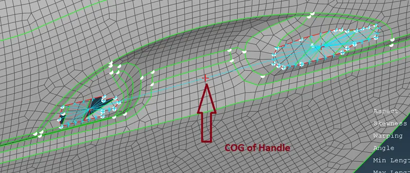
Now we asssign some mass (100gm) to Door Handle
Command: NASTRAN (deck) >> ELEMENTs >> CONMi >> CONM2 >> Nodes >> selecting COG node or Node where we need mass representation >> CONM2 CARD will open ( we edit Name as Door_Handle and put mass value in tonnes) >> ok
The final view of Door Handle is given below
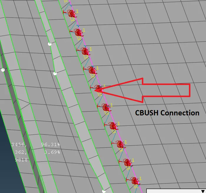
- CBUSH Connection: - in this connection type we use damping material for connection. Generally, we use CBUSH connection near the glass edge.
Command: Topo >> Curves >> Cons2curves >> Featureline (Feature Section) >> selecting all four edge of window glass...
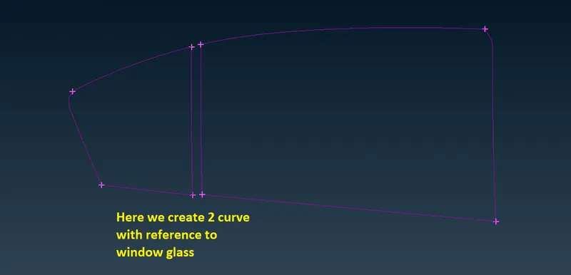
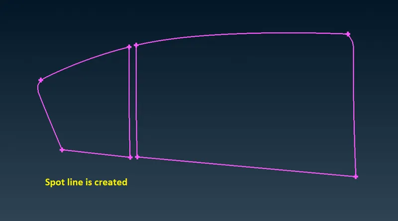
Now we convert these two curves into Spot line
Command: Assembly >> Convert >> Curves >> select Curves >> middle mouse click >> Spot Line >> OK
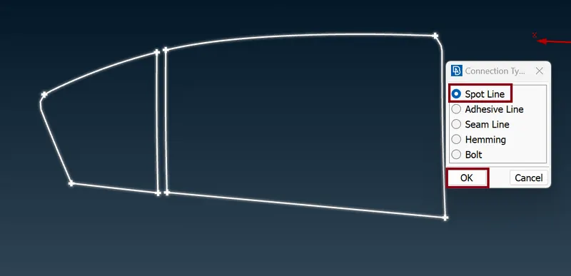
spot Line is created
Now we go to: Connection Manager >> Select Spot Weld line >> Hit Middle mouse click >> Edit Connection Manager as per figure given below
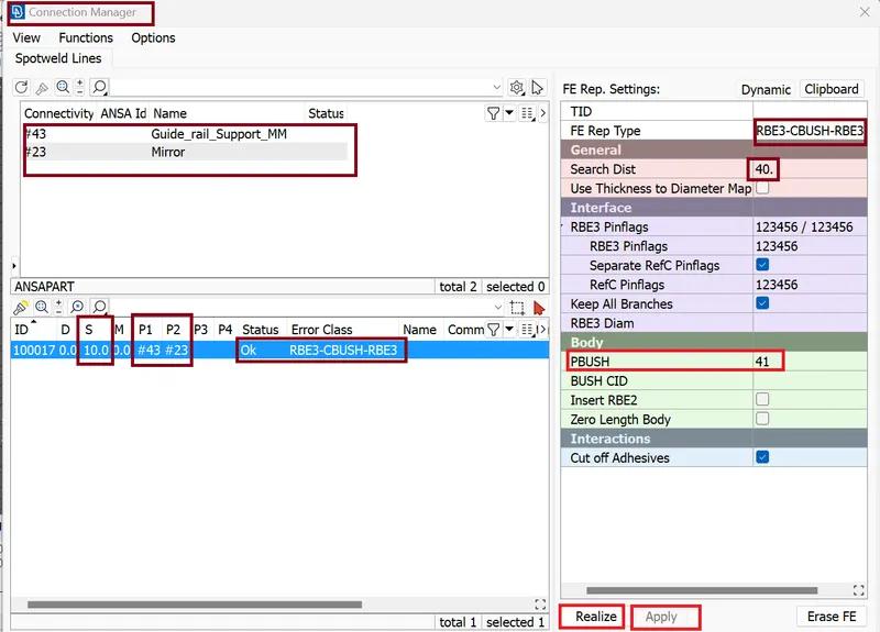
Hit apply and Realize.
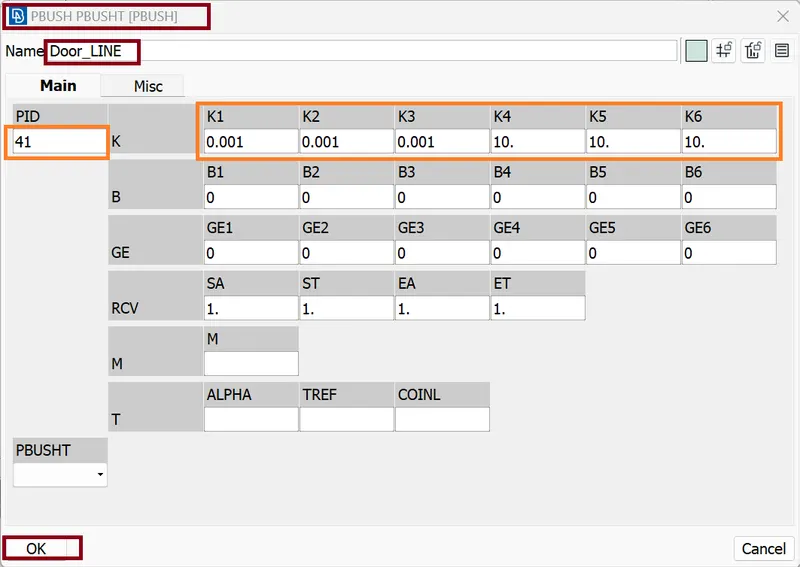
Here we create PBUSH PIDs and edit them as per figure
Now finlly we gate CBUSH Connection
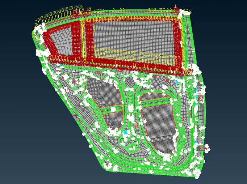
Similarly we use CBUSH Connection in all four side for both glass as shown in below
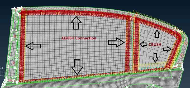
Finally we have
LEARNING OUTCOME:
- We learn how to assign PID for various parts as per our requirement.
- Here we learn various type of connections like BOLT Connection, RBE2 Connection, Spotweld Connection and CBUSH Connection.
- We learn how assign mass to any Connection Nodes.
CONCLUSION:
The PIDs are assigned to the various parts in the given model as per our requirement.
Here we work on
- Rigid body element connection
- assigning Mass to Door Handle.
- Spot welding component connection.
- CBUSH element Connection
All objectives are satisfied.
*************************************************************************************************************************************************************************************************************************************************************************************************************END