Week 4- Rolling operation
AIM: To Perform Static-Structural Analysis/Simulation for Rolling Operation.
OBJECTIVE:
To simulate the rolling operation and find out
- Equivalent stress for the whole setup
- Equivalent Plastic strain for the workpiece
- Directional Deformation in the Z axis for the workpiece
- Prove that the workpiece has displaced by 90mm
THEORY:
Mechanical rolling is a metalworking process that involves deforming a metal object by passing it through a set of rollers. The rollers compress the metal, reducing its thickness and changing its shape. Rolling is a widely used manufacturing process that is used to produce sheet metal, plate metal, and other metal products with precise dimensions and properties. In rolling operation, the metal is placed between two rollers, which rotate in opposite directions. The rollers exert a force on the metal, causing it to deform and take on the shape of the rollers. The metal is pulled through the rollers, and the gap between the rollers is adjusted to achieve the desired thickness.
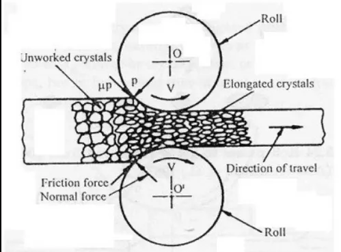
There are several types of mechanical rolling operations, including:
Hot rolling: In this process, the metal is heated above its recrystallization temperature to make it easier to deform. Hot rolling is used to produce sheet metal and plate metal for a wide range of applications.
Cold rolling: In this process, the metal is rolled at room temperature, which increases its strength and hardness. Cold rolling is used to produce sheet metal and plate metal for applications that require high strength and durability.
Roll forming: In this process, the metal is gradually bent into a specific shape by passing it through a series of rollers. Roll forming is used to produce products such as metal roofing and siding, window frames, and automotive parts.
Mechanical rolling operations require precise control of the rolling process to achieve the desired dimensions and properties of the metal product. The rollers must be properly aligned and maintained to ensure consistent results.
ANALYSIS SETUP:
Here we will start our work Structural Analysis for Rolling {Copper} Operation. we will put a Copper Rod between two Rolls and extract the sheet form of copper metal.
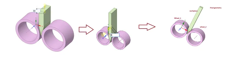
- Given Geometry:
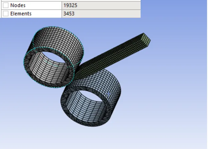
- Mesh:
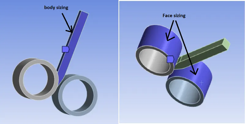
Details:
- Global Element Size: Default
- Body Sizing: Workpiece
- Element Size = 4.0 mm
- Face Sizing: Wheel_1 & Wheel_2
- Element Size = 4.0 mm
- Material:
Copper Alloy NL
Density: 8300 Kg/m3
Young’s Modulus: 1.1 E+05 MPa
Poisson’s Ratio: 0.34
Yield Strength: 280 MPa
Tangent Modulus: 1150 MPa
Initial Steps:
- Import model in Static Structural named as “Skill_Lync_Copper_Rolling.stp” in Geometry section.
- Change in the geometry as follows:
- Increase length of Copper Workpiece by 60 mm.
- Decrease width of Copper Workpiece by 8 mm.
Connections:
Very first we need to Delete automatically created contacts and create new contacts as given below
Contact: 1st one
Contact Body = workpiece
Target Body = Wheel_1
Contact: 2nd one
Contact Body = workpiece
Target Body = Wheel_2
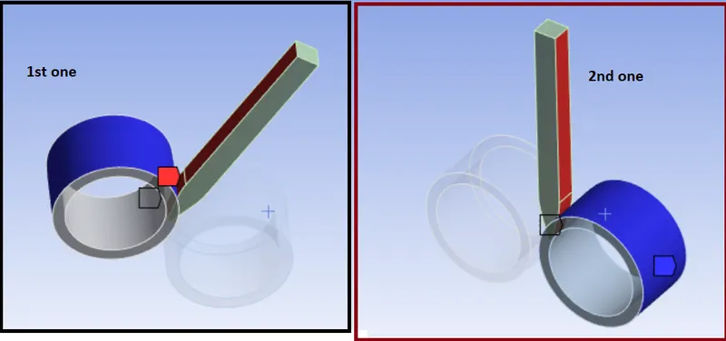
Settings we need to edit for Both the Contacts.
Type: Frictional
Friction Coefficient: 0.2
Formulation: Augmented Lagrange
Normal Stiffness: By factor
Normal Stiffness Factor: 0.1
Update Stiffness: Each Iteration
Interface Treatment: Add Offset, Ramped Effects
Joints:
Joint: 1
Connection Type: Body-Ground
Type: Cylindrical
Body: Wheel_1
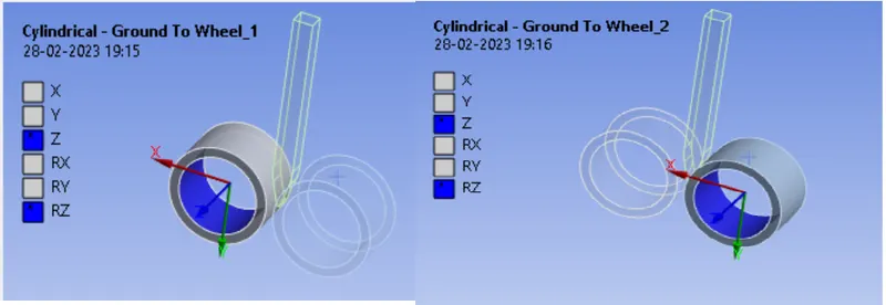
Joint: 2
Connection Type: Body-Ground
Type: Cylindrical
Body: Wheel_2
- Boundary Conditions settings:
Analysis Settings:
- Number of Steps: 14
- Auto Time Stepping: Program Controlled
- Solver Type: Program Controlled
- Large Deflection: ON
- Nonlinear Controls:
- Stabilization: Constant
- Method: Energy
- Energy Dissipation Ratio: 0.1
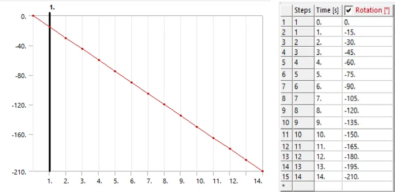
Here we want Rolling operation for this we need give motion to both the wheels and also we need to give motion to workpiece.
So, we have to give different displacements in order to move the work piece
Other Boundary conditions for joints
Displacement:
For workpiece
Direction: Y axis (Negative)
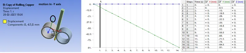
Joint Load: 1 and Joint Load: 2 {for both the wheel}
Joint: Revolute – Ground to Wheel_1 and Revolute – Ground to Wheel_2
Type: Rotation
Magnitude: Tabular Data
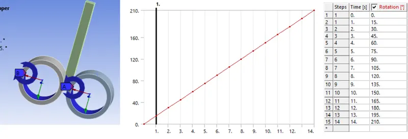
Wheel direction of rotation is different but magnitude is same
SOLUTION
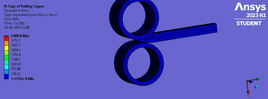
After giving proper boundary conditions, create desired solutions for output results. Create Solutions for Equivalent (Von Mises) Stress for whole setup, Equivalent (Von Mises) plastic Strain for the work piece and and Directional Deformation in Z -axis.
- Stress induced in Whole Setup
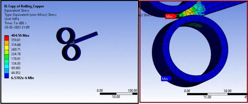
- Stress Plot {Whole Setup}
Comments:
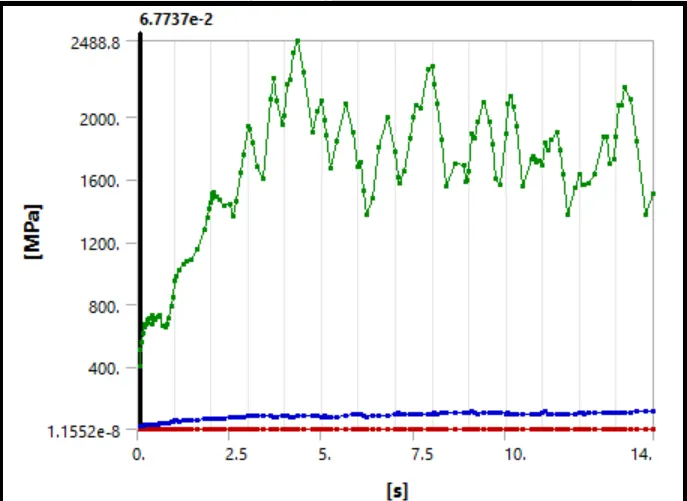
The initial increase in the magnitude of Equivalent Stress is attributed to the fact that, in the beginning there is increase in material amount, which get compressed in the gap between the rollers. This causes more material to resist the deformation & hence high values of Stresses develops. Also, rollers apply pressure to the material, it undergoes plastic deformation, which causes it to experience compressive stresses in the rolling direction and tensile stresses in the transverse direction. These stresses are distributed unevenly across the material, with the highest stresses being concentrated at the edges of the rollers.
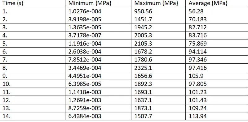
- Detail stress result on whole setup
Animation...
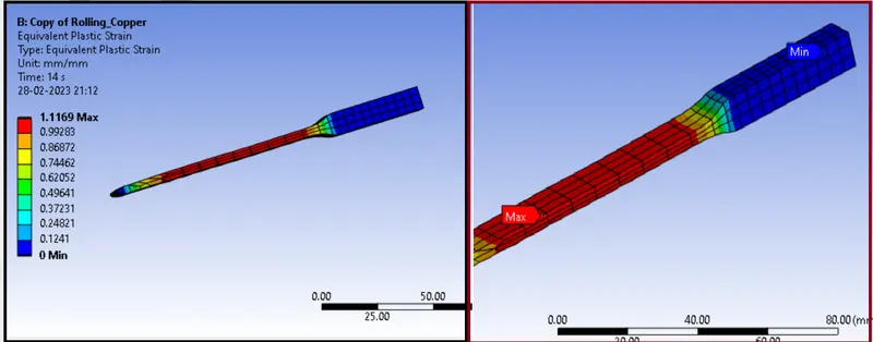
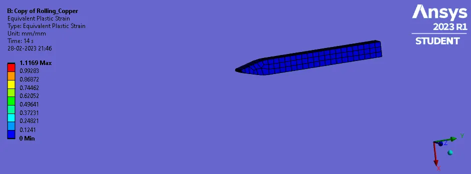
- Plastic Strain on {workpiece}
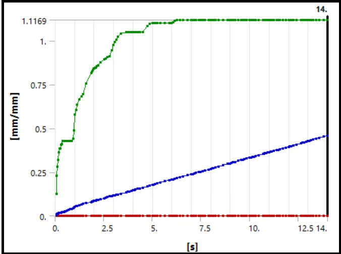
- Plastic Strain plots
Comments:
We observe here Plastic deformation in copper during the operation occurs and we know that when plastic deformation occurs (force is applied to a copper material that exceeds its yield strength). As the copper material is compressed, its thickness decreases and its length increases, resulting in a reduction in its cross-sectional area. Copper is a ductile material that exhibits good plastic deformation properties. Therefore, it can be rolled into thin sheets or wires without fracturing or cracking.
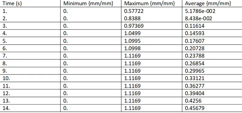
- Detailed strain result on workpiece
Animation...
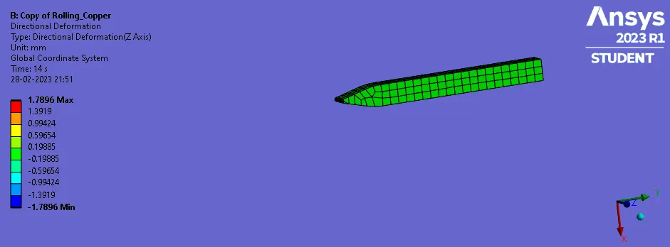
- Directional Deformation for workpiece in Z-Axis
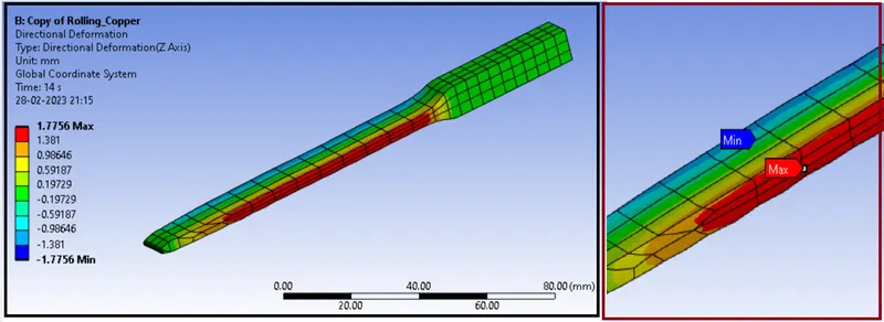
- Directional Deformation {for workpiece} plots
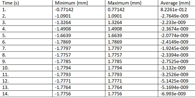
- Detailed Directional Deformation {for workpiece} results:
Animation...
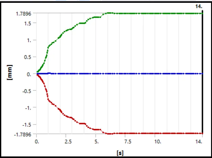
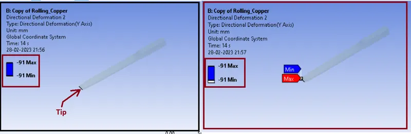
Directional Deformation of the workpiece tip in Y-axis
Plots
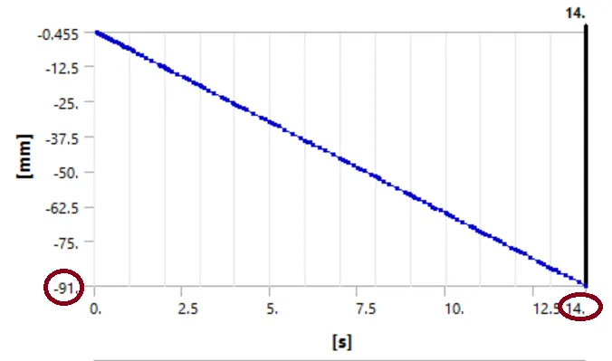
Here we can observe from plots the directional deformation of the workpiece tip along the lengthwise direction. It is observed that the way in which deformation occurs is almost exactly similar to the boundary displacement condition hence confirming the displacement of workpiece is approximately 90 mm.
Maximum Values over time
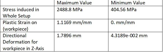
The above tabular data shows the equivalent stress, Equivalent Plastic Strain, directional deformation (Z-Axis). Copper experiences a maximum equivalent stress of 2488.8 MPa, for the whole body, Equivalent Plastic strain for the workpiece is 1.1169 , Maximum Directional Deformation in the Z axis for the workpiece is 1.7896 mm, we has Proved that the workpiece has displaced by Approximately 90mm by assigning the displacement value randomly.
Application
The Rolling operation has several important applications in various industries, including:
- Production of Sheet Metal: Mechanical rolling is commonly used to produce sheet metal with precise thickness and surface quality. The process helps to eliminate defects and improve the mechanical properties of the material, making it suitable for various applications.
- Manufacturing of Structural Components: Mechanical rolling is also used to manufacture structural components such as beams, columns, and tubes. These components are widely used in the construction and engineering industries for their strength and durability.
- Cold-Forming: Mechanical rolling is an essential process in cold-forming operations. It is used to form metal parts and components without heating the material, which saves time and energy.
- Automotive Industry: The automotive industry uses mechanical rolling to produce various components such as car body panels, wheels, and suspension parts. The process helps to achieve the required thickness and surface finish for these components.
- Aerospace Industry: Mechanical rolling is also used in the aerospace industry to produce components such as wings, fuselages, and engine parts. These components require precise tolerances and high strength, which can be achieved through mechanical rolling.
Overall, mechanical rolling is an important process in the metalworking industry that helps to produce high-quality components with the required thickness, surface finish, and mechanical properties.
CONCLUSION:
From the above result we can conclude that the equivalent stress of copper Alloy NL is 2488.8 MPa. The workpiece has displaced by 91mm is proved by adding a random value to the displacement, upto 91mm and the tip of the workpiece is chosen as Geometry and by the directional deformation the workpiece is displaced Approximately 90 mm as shown in above figure.
***********************************************************************************************************************************************************************************************************************************************************************END
Thanks & regards,
Devesh kashyap