Project - 2 - Meshing on the suspension Assembly
AIM: To Mesh the given (rear suspension assembly) Model with 2D & 3D meshing (Volume meshing) as per the given quality criteria and deployed the connection between the sub components.
OBJECTIVE:
- To perform Geometry Clean-up.
- To Extract Mid surface for uniform thickness Components & deployed 2D meshing.
- To perform Solid & Volume Meshing.
- To performed appropriate connections to connect the component
- To perform Symmetry for Replication.
Given Quality Criteria
- Quality Criteria for Surface Meshing of Tyre and Rim (Element type: Tria)
|
S.No. |
Quality Criteria |
Value |
|
1. |
Average length |
6.5 |
|
2. |
Minimum Length |
5 |
|
3. |
Maximum Length |
10 |
|
4. |
Skewness |
45 |
- Quality criteria for Surface Meshing of Non Uniform thickness components other than Tyre and Rim (Element type: Tria)
|
S.No. |
Quality Criteria |
Value |
|
1. |
Average length |
4 |
|
2. |
Minimum Length |
2 |
|
3. |
Maximum Length |
6 |
|
4. |
Skewness |
45 |
- Quality Criteria for Volume meshing of all non-Uniform thickness components (Element type: Tetra Elements)
|
S.No. |
Quality Criteria |
Value |
|
1. |
Tet-collapse |
0.2 |
- Quality criteria for Mid surfacing of Uniform thickness part which has thickness less than 5 mm (Element type: Mixed elements)
|
S.No. |
Quality Criteria |
Value |
|
1. |
Average length |
4 |
|
2. |
Minimum Length |
2 |
|
3. |
Maximum Length |
6 |
|
4. |
Aspect |
3 |
|
5. |
Warpage |
15 |
|
6. |
Skewness |
45 |
|
7. |
Jacobian |
0.7 |
|
8. |
Minimum Quad Angle |
45 |
|
9. |
Maximum Quad Angle |
135 |
|
10. |
Minimum Tria Angle |
30 |
|
11. |
Maximum Tria Angle |
120 |
THEORY:-
The rear suspension is the mechanical system that holds the car’s body and frame aloft as the connection between the car and the road. The rear suspension includes the frame (or body connections in a unibody vehicle), joints, bearings and bushings, rods, shock absorbers, springs, wheels, and tires. The rear suspension’s job is to work with the front suspension to conduct the car down the road smoothly and to keep it under control while it travels. On a basic level, the rear suspension prevents the vehicle’s body from contacting the ground and keeps the tires in contact with the road.
ensuring steering stability and smooth handling to delivering a comfortable ride, the suspension system plays a key role in the performance of the vehicle.
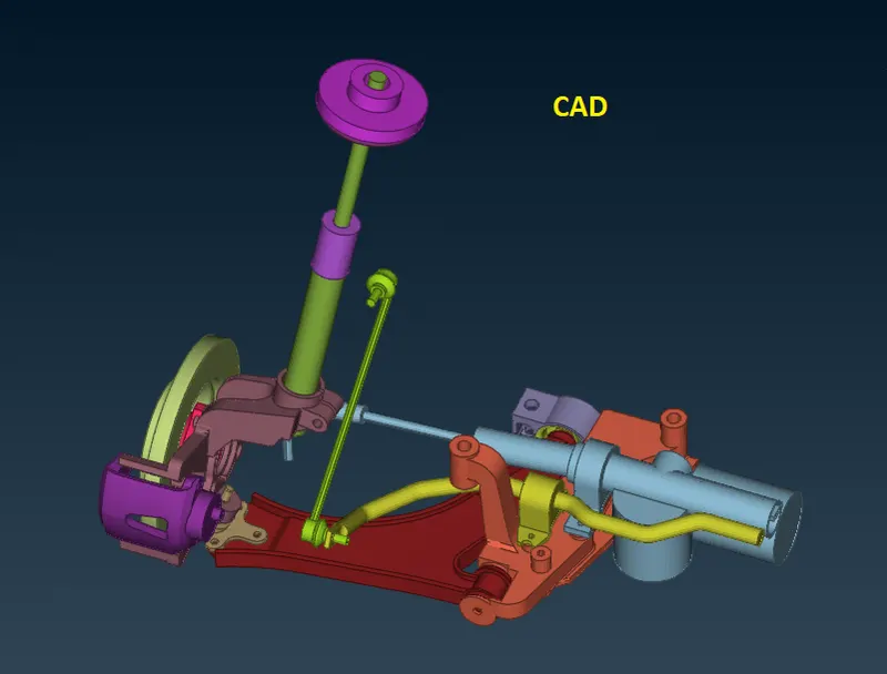
Modern day suspensions are composed of different parts, and vehicles vary tremendously in their suspension designs, but every suspension is composed of certain basic parts which are common in all, some of which are shown below.
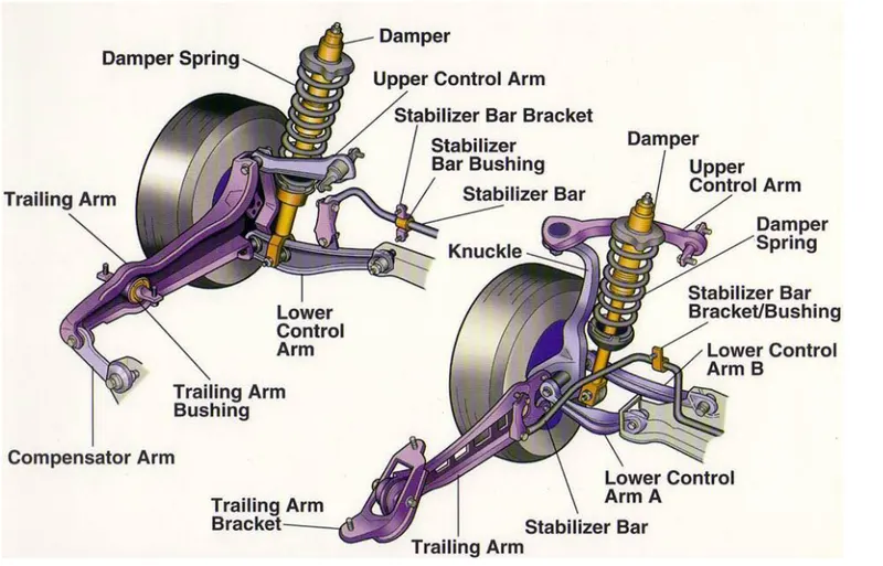
Given model Pictorial view
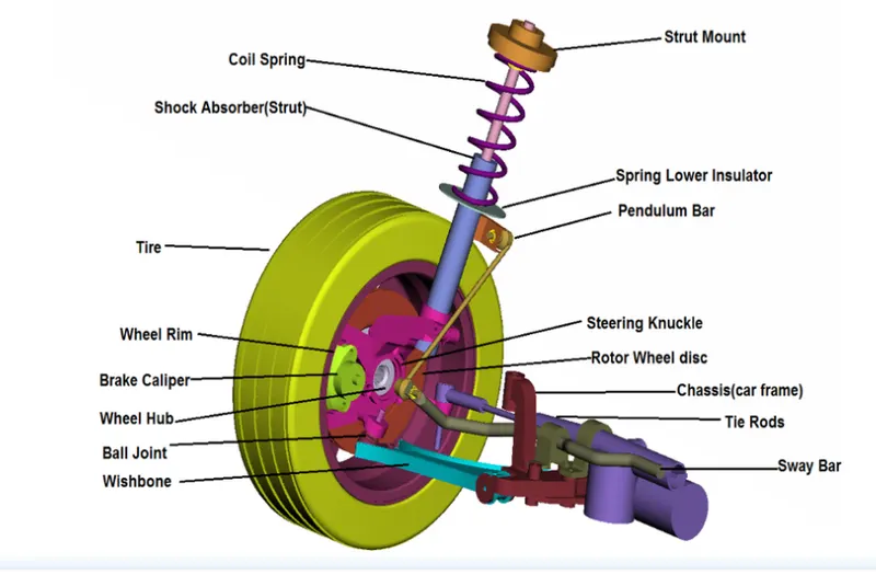
The basic components of a suspension system are as follows:
1.) BALL JOINTS - ball joints provide a pivot point for each wheel to pivot, or turn upon, as the steering system turns the front wheels left and right and the control arms move up and down.
2.) SHOCK ABSORBER - Shock absorbers work on the principle of fluid displacement on both the compression and extension cycle. The primary purpose of the shock absorber is to control spring and suspension movement. This is accomplished by turning the kinetic energy of suspension movement into thermal energy, or heat energy, to be dissipated through the hydraulic fluid. All modern shock absorbers are velocity-sensitive hydraulic damping devices - meaning the faster the suspension moves, the more resistance the shock absorber provides.
3.) STRUT - A strut is a major structural part of a suspension. It takes the place of the upper control arm and upper ball joint used in conventional suspensions. Because of its design, a strut is lighter and takes up less space than the shock absorbers in conventional suspension systems. Struts perform two main jobs. First, struts perform a damping function like shock absorbers and second struts provide structural support for the vehicle suspension, support the spring, and hold the tire in an aligned position. Additionally, they bear much of the side load placed on the vehicle's suspension. As a result, struts affect ride comfort and handling as well as vehicle control, braking, steering, wheel alignment and wear on other suspension parts.
4.) STABILIZER BAR - A stabilizer bar tries to keep the car's body flat by moving force from one side of the body to another. When we taking a turn the part of the car on the outside of the turn gets pushed down toward the road and the part of the car on the inside of the turn rises up. In other words, the body of the car "rolls" 10 or 20 or 30 degrees toward the outside of the turn. If you take a turn fast enough, the tires on the inside of the turn actually rise off the road and the car flips over. Roll is bad. It tends to put more weight on the outside tires and less weigh on the inside tires, reducing traction. It also messes up steering. What you would like is for the body of the car to remain flat through a turn so that the weight stays distributed evenly on all four tires. in simple word we can say it limits the body roll of the vehicle during cornering.
5.) CONTROL ARM - The control arms are one of the core components of a suspension system and serve as the direct connection points between the front wheel assemblies and the vehicle's frame. The control arms allow a driver to steer a car while also guiding the wheels up and down with the road surface. in other words we can say it is a movable lever that fastens the steering knuckle to the vehicle frame or body.
6.) CONTROL ARM BUSHING - Control arm bushings are important for driving comfort and handling. They cushion the suspension system which in turn controls noise and vibrations, and also provide a softer ride over bumps. Bushings can flex and move while retaining stiffness and the ability to return to their original shape and position. or we can say it is a sleeve, which allows the control arm to move up and down on the frame.
7.)STRUT ROD - A Strut Rod is used in a variety of suspensions and provides bracing to the (usually lower) control arm to limit front and rear movement. Some also allow for adjustment of caster during alignment. in other word we can say it is prevents the control arm from swinging to the front or rear of the vehicle.
8.) SPRING - springs are the link between wheels and car body. Their primary task is to compensate uneven road surfaces. And secondary they must ensure that the wheels always have safe contact with the road regardless of its condition. suspension springs are one of the most safety-critical components of modern vehicles. They affect handling, roadholding and braking performance.
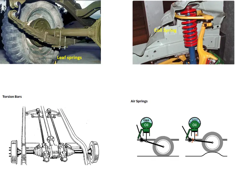
Modern springing systems are based on four basic designs - leaf springs, coil springs, torsion bars, and air springs.
a.Leaf springs - Leaf springs are made up of a cascading set of blades held together by a U-bolt. The different lengths of the blades allow for the steady support for the entire vehicle the next while remaining flexible. First used on horse carriages, leaf springs were widely used in the rear suspension of cars until the late ’80s, but has since been abandoned for newer systems.
Pros: Leaf springs can take on the heaviest of loads, which is why they are still pretty common in heavy-duty trucks and commercial vehicles.
Cons: They are very noisy, a lot bulkier, and provide a more rigid ride than today’ systems.
b.Coil Springs - it is a helical type of spring, which is basically a heavy-duty torsion bar wound around an axis.
Pros: can take on heavy loads.
Cons: extremely bouncy.
c.Torsion Bars -it is a type of spring relies on the twisting properties of a straight steel rod to mimic the performance of coil springs. Attached to the vehicle’s control arm, the rod gets twisted along its length as the arm moves up and down.
Pros: very affordable, easy to maintain and replace.
Cons: it won’t be able to handle bumps very well.
d. Air Springs – it relies on the compressing quality of air to absorb impact. Air springs are made up of a cylindrical air chamber strategically placed between the undercarriage and wheel.
Pros: extremely smooth performance, with these springs, a car is literally floating on air.
Cons: very expensive, tend to fail more frequently.
PROCEDURE/STEPS:
- Importing the CAD model
Command: File >> Open >> Project_1_Ip_Console_Half_22dec
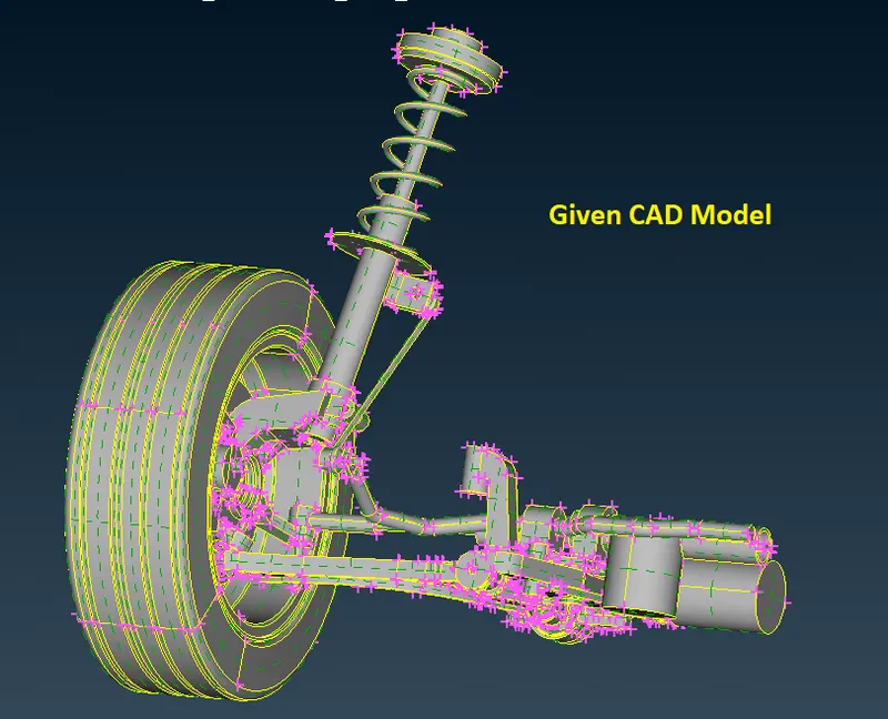
Here we closely observe surfaces are attached in proper way and no orientation issue.So, Tropological clean up is not required. We jump on Geometry clean up.
- Geometry Clean up
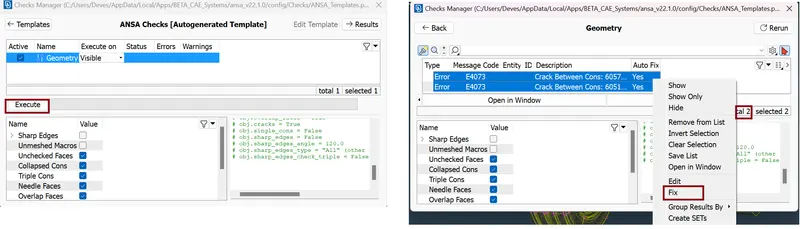
We Observe whenever CAD model is imported into the ANSA, there might be several geometrical errors like intersecting surfaces, missing/distorted surfaces etc. due to the format conversion process or inherent bad model. And, it is important to clear all these errors before starting meshing.
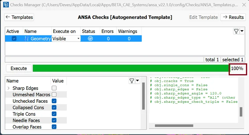
Command: Tools >> Checks >> Geometry >> Execute.
after auto fix
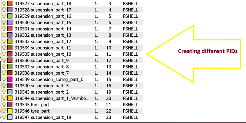
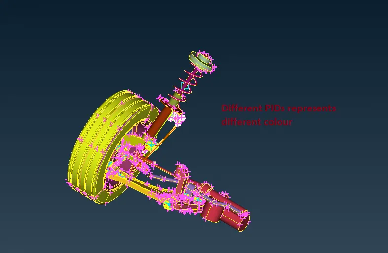
- Creating different PIDs
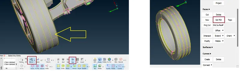
Now we need to assign different PIDs so that it will be easy to work on them.
Command: Focus >> !Not >> PID Region (Feature section) >> selecting the component >> hit middle mouse click >> Topo >> Set PID >> select the component >> New >> PSHELL >> Edit the Name and Thickness >> hit ok.
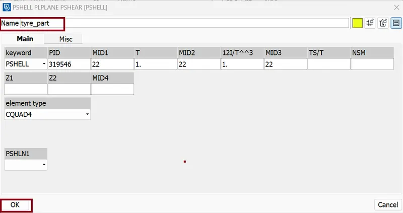
Similarly we create PIDs for all the components
- 2D MESHING and VOLUME MESHING for Non-Uniform Thickness Parts
Surface Meshing (2D Meshing) :- After geometry clean-up and PIDs generation we need to filter out component for solid meshing, we use solid Meshing for component having non uniform thickness. each part is Meshed using ortho trias or normal trias. Ortho trias are mainly used in areas where there is complex shapes or curved areas, like fillet region. Normal trias are used in areas where it is flat. Before Meshing we need to defeaturing (avoid feature areas/lines) the component for better Mesh flow.
2D Meshing & check quality criteria for Non Uniform thickness components other than Tyre and Rim.
Here we have to check (Geometry check) for every PID component in model. In case if we find any error, fix that by AUTO FIX option or fix it manually. After fixing everything, Using Command: Classic Mesh >> Perimeters >> Length >> select the entire Component (window selection) >> change the to TARGET elements length > parameters/Macros >> ok. It will help to place the node at interval of target length. In this model maximum components are of non-uniform thickness and thickness more than 5mm. So, for this type of components, we have to do VOLUME mesh. For Volume mesh, first we have to do the surface mesh using TRIAS & ORTHO TRIAS and the converting those surface mesh to Volume mesh. Here We will prefer ORTHO TRIAS for curve surfaces as it will capture the feature more accurately as compared to normal TRIAS and NORMAL TRIAS for straight surfaces.
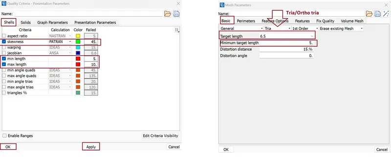
Setting Quality Parameters
quality parameters are configured by using command: Utilities >> Quality Criteria.
similarly Next we open Utilities >> mesh parameters and edit parameter as per figure given below.
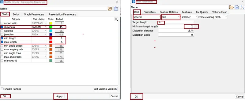
For surface Mesh we use Command: Classic Mesh >> Mesh Generation >> Best/Spot Mesh >> selecting the faces one by one >> hit Middle mouse click.
mesh is refined by using command: Shell Mesh >> Reconstruct / Improve/ Smooth. Also we are able to fix quality failure element while using this Command.
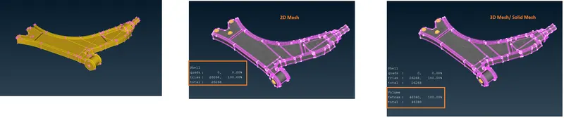
VOLUME MESH/3D MESH:
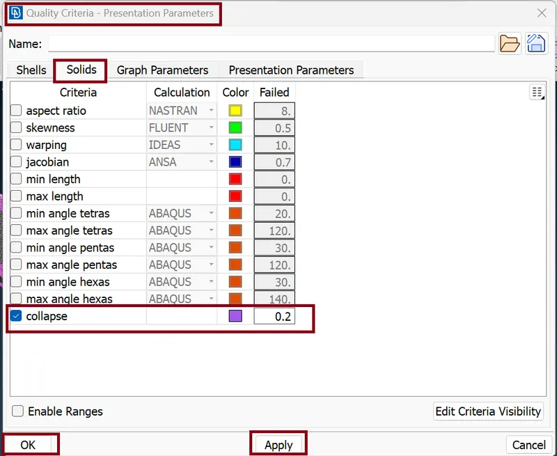
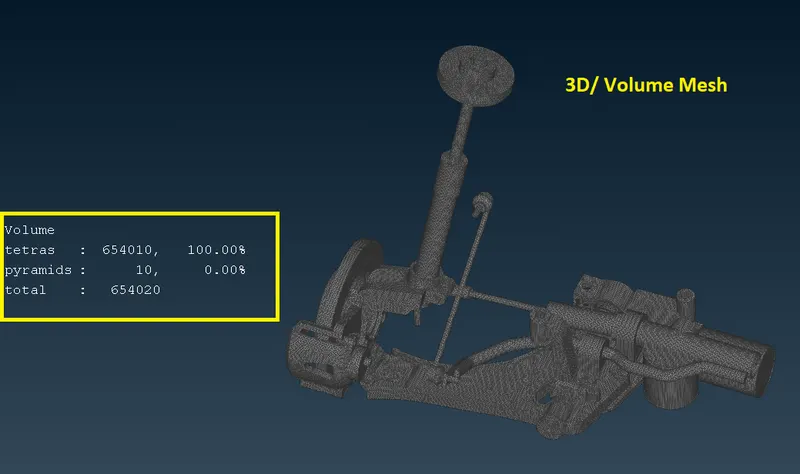
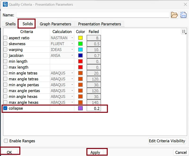
Parallelly, we work on VOLUME MESH also. set the QUALITY CRITERIA for volume mesh.
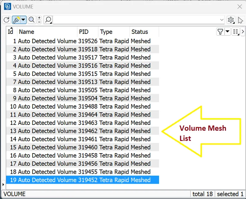
For Volume mesh we use Command: Volume Mesh >> Volumes >> Define >> Detect on “Selected” >> select the Component >> ok >> Volume list will open >> select the auto Detected Volume >> Ramesh with Tetra Rapid Element.
It is very important that, there should not be RISE & KINK in the model. If these Type of Error in the model we need to remove it properly so that there will be no TET COLLAPSE issue.
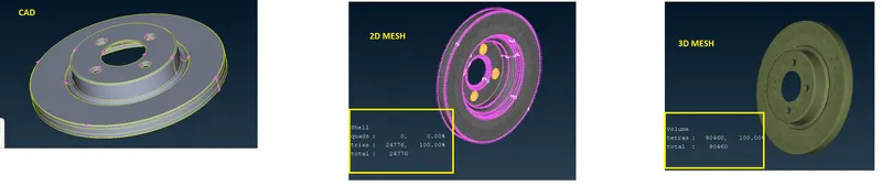
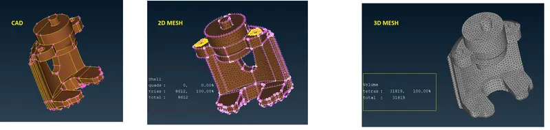
Similarly we work on different Component (PIDs)
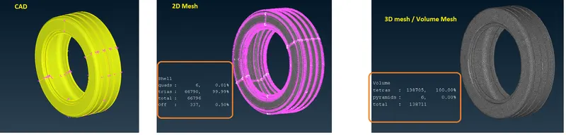
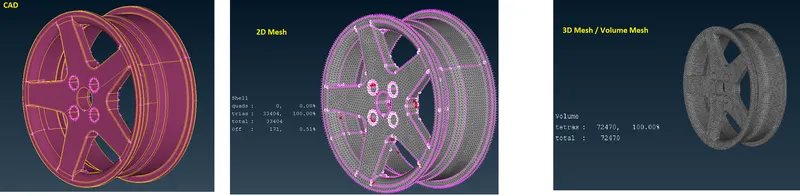
Tyre and rim having different quality criteria for surface meshing
Result for tire
Result for Rim
Volume Mesh List
Checking for TET COLLAPSE failing Elements
TET COLLAPSE is one of the quality parameters, which will be checked while generating tetrahedral elements. It can be calculated by measuring the distance of a node from the opposite face, then each of the four values will be divided by the square root of the opposite face's area.
We can Fix the TET COLLAPSE by two Command: –
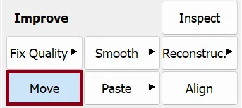
Command1: Volume Mesh >> Improve >> Fix Quality
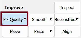
Command2: Volume Mesh >> Improve >> Move
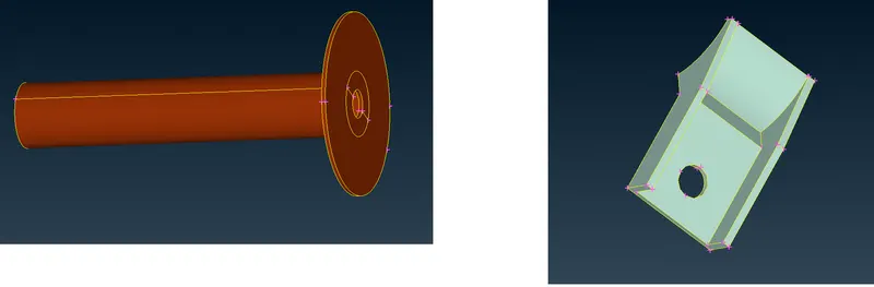
MESHING of uniform thickness parts:
in this Model these 2 Component having uniform thickness and thickness is less then 5mm.
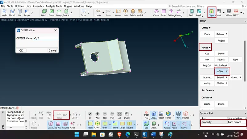
Mid-Surface generation:
For this we use Command: Topo (deck) >> Faces >> Offset >> Faces >> Switch ON the Feature Area (Feature Selection) >> selecting the face by right click
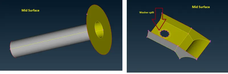
Our mid surfaces are generated
Thickness Assignment:
We can now assign the thickness to the parts by going to FACES > > Set PID then click on the part which we need to assign thickness. Then from the coming window Right click >> New >> PSHELL. Double click on the property created, which will assign that property to the part we selected and giving the original thickness of the parent geometry in the details of the property will give the part the thickness.
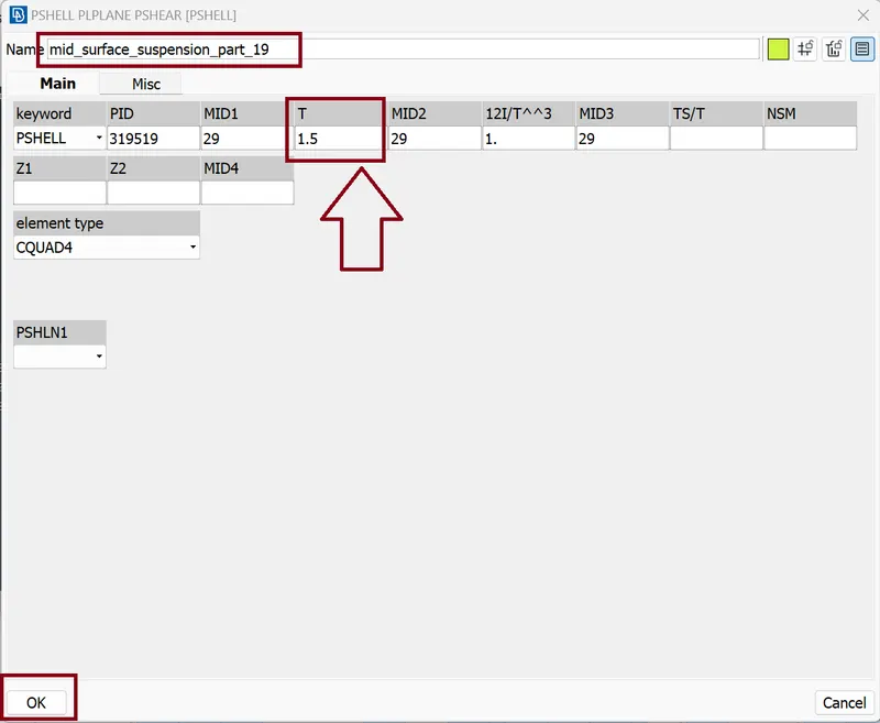
Similarly, we create for Second components.
2D Meshing
Now we go for meshing, very first we assign Quality Criteria and Mesh Parameters.
Setting Quality Parameters: The quality parameters are given, we put this value as per given figure.
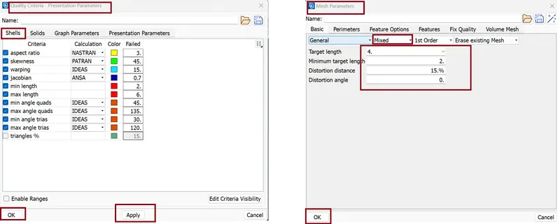
Setting mesh parameters:Here we edit target length would be 4mm, mesh type would be 'mixed' & the minimum lengths would be 2mm.
next step is to prepare the mid surfaces for meshing follows these steps
- All the areas are checked for minimum element length and altered where elements might fail for minimum length.
- CONS that are not essential to define a feature are removed by joining the surfaces using Macros >> Join >> selecting CONS and press left click (this will work in Classic mesh mode) in Topo mode we use Faces >> cut >> selecting CONS by right click. for generating CONS we use Macros >> cut >> selecting CONS and press left click in Classic mesh mode and in Topo Faces >> cut >> selecting and press left click.
- holes are rotated using Perimeters >> Slide >> Hotpoint’s >> Mark/Un tool to ensure the CONS are parallel to the nearby CONS.
meshing is done using the Mesh generation >> Best tool. This tool generates the mesh using the best algorithm applicable in selected area.
created mesh is refined by using command Shell Mesh >> Reconstruct. It is ensured that there are no rotating quads. Also, trias are kept as low as possible.
Things need to be ensured while meshing
- Avoid back-to-back triangle.
- Avoid opposite trias.
- Avoid triangle element at the edges.
- To fix Elements quality Criteria and trias are removed using >>Split, >>Swap, >>Join (Elements Tab), >>Smooth (Shell mesh tab), >>Paste (Grids), and >> Num +/- (perimeter tab).
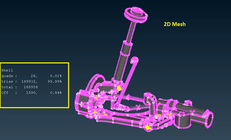
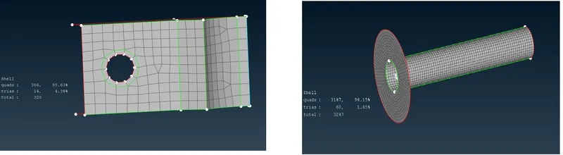
2D Mesh Result
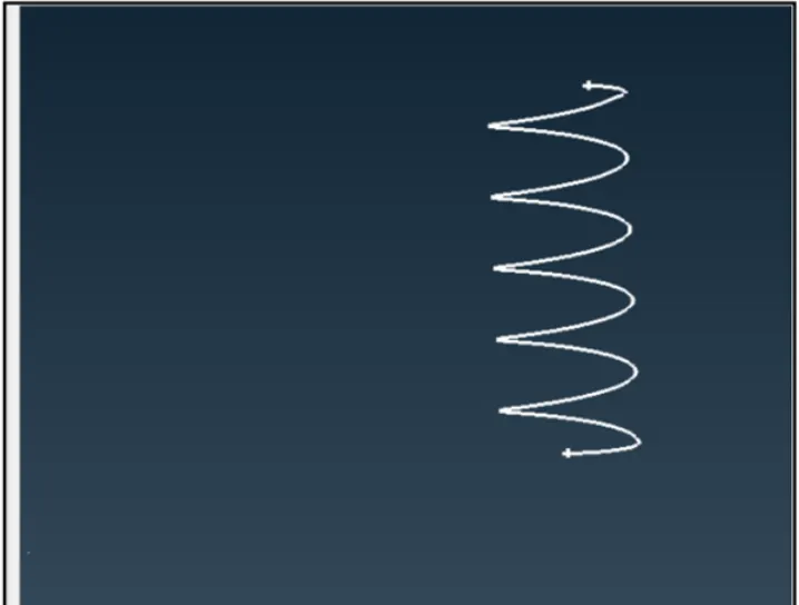
CREATING SPRING
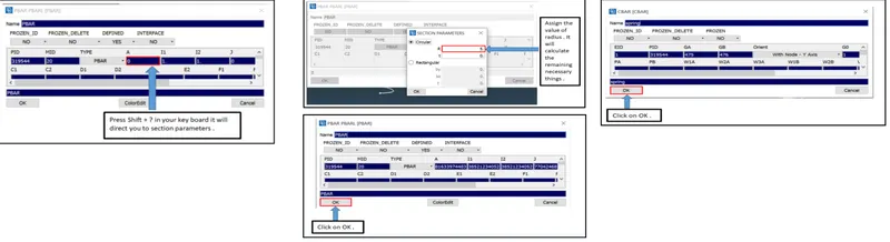
- Generate a middle curve for the spring. By using the middle option in the curves.
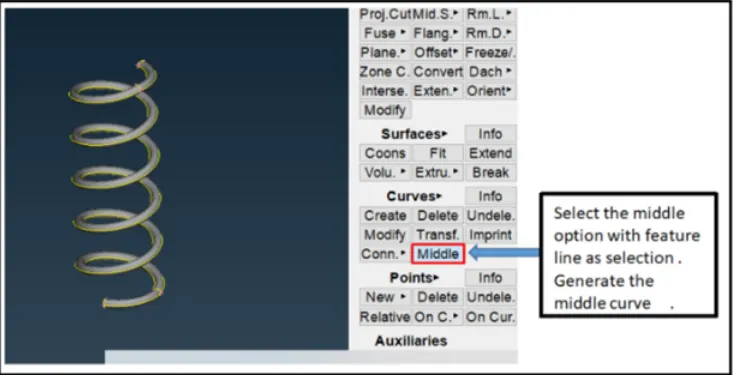
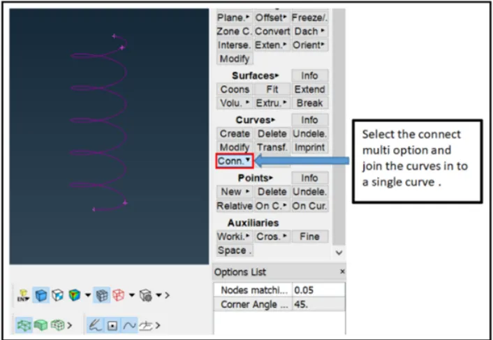
2. Connect the curve into a single curve. By using the connect>multi option in curves.
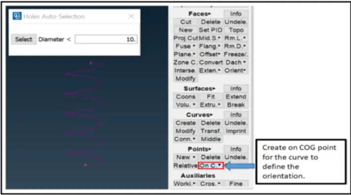
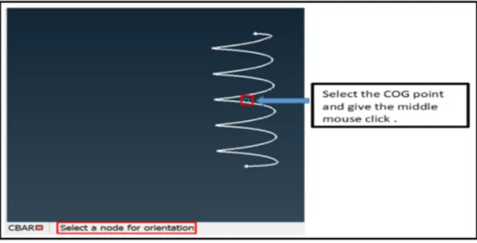
3. Create a COG point for the curve to define the orientation. By Points> On COG
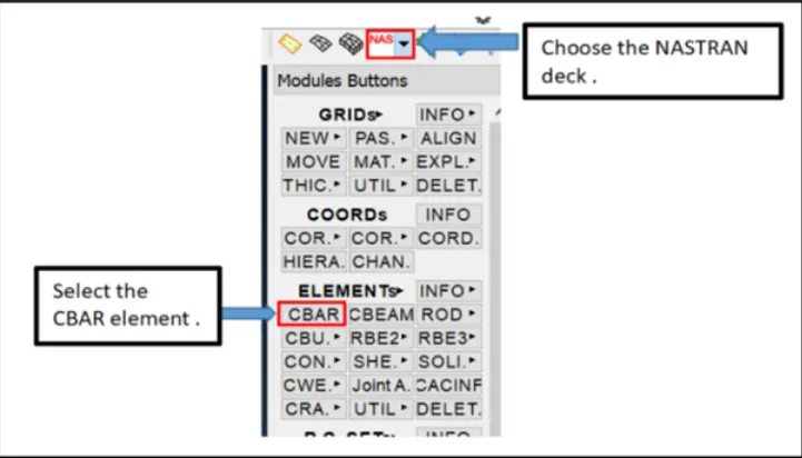
4. Now we go to NASTRAN Deck. Select the CBAR element.
5. Change the selection type to the curve box.
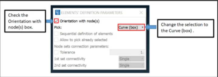
6. Select the curve and give the middle mouse click.
7. select the orientation node. (The COG point).
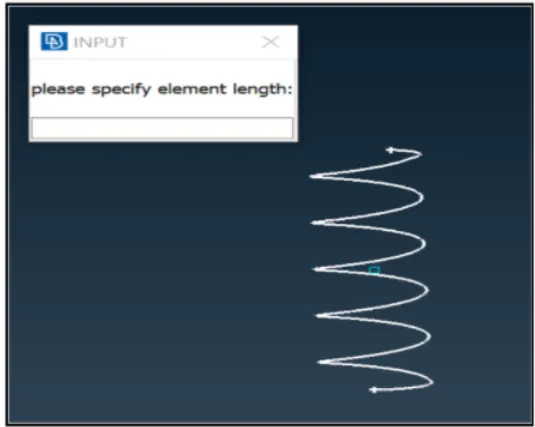
8. Now we specify the element length. In this case, The Element length is taken as 4 mm, hit middle click.
9. After Specifying the element length as 4 mm, do middle mouse click and define a PID by creating a new PID.
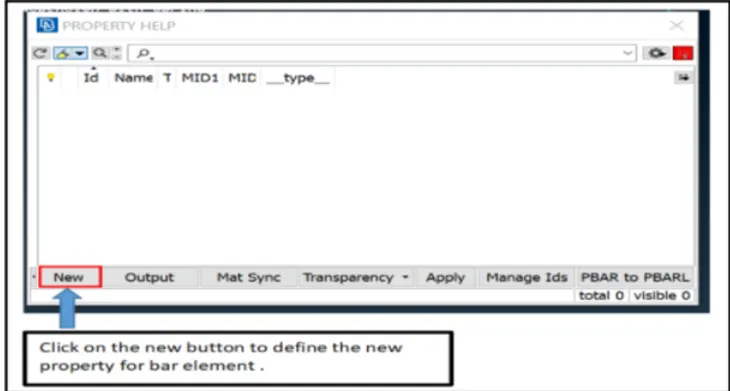
10.Define Area by giving Radius of spring. i.e., Cross section radius of a spring. After that, assign the cross-sectional radius of the spring element. It will calculate the cross-sectional area and moment of inertia.
11. Finally, 1D bar elements will be created.
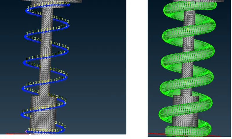
A CBAR elements is a type of simplified CBEAM element and this should be used whenever the cross section of the structure and its property is constant and symmetrical.
CONNECTIONS
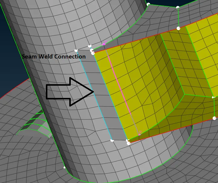
a.) Seam Weld Connection
In automobile Sector two types of weld Connection are used SPOT WELD Connection & SEAM WELD connection. SPOT WELD is seen in cars body structural components i.e., BIW structure. SEAM WELD is used in load carrying areas.
SEAM WELD that are commonly used are OVERLAP SHELL & Y-JOINT SHELL. Overlap shell is a type of FE representation which always used when the 2 parts are to be welded are PARALLEL to each other, whereas in case of Y-Joint shell are used when 2 parts are perpendicular or inclined to any angle each other.
- Verry first we create a curve (Where we require seam weld ) convert this curve into seam weld line and then go to Connection Manager and edit the card as per figure below.
Command: Convert >> Curves >> Select the curve >> hit middle mouse click >> select Seam Weld >> hit OK.
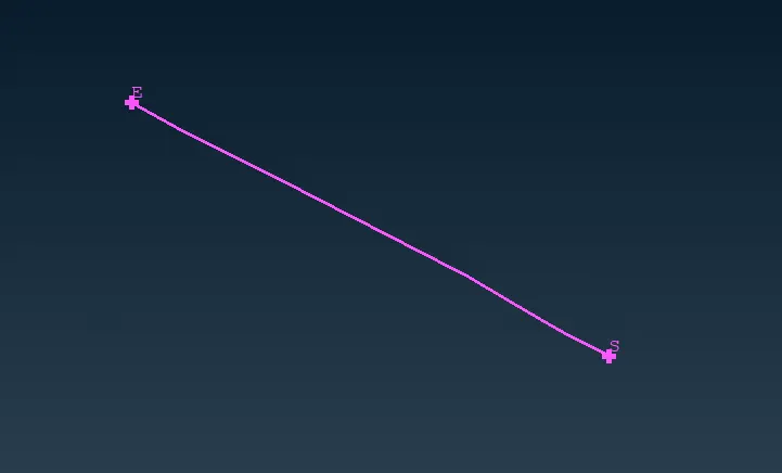
Command : Go to Connection Manager >> Select the seam weld line and hit middle mouse click >> Connection Manager tab will open and we edit this tab as per figure.
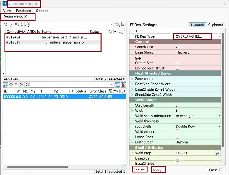
Finally, we have SEAM WELD Connection.
b.) RBE2 Connection - RBE2 type connection are rigid connection (it means all 6 degrees of freedom are restricted). Any rigid type of connection having two Nodes Master Nodes (Independent Nodes) and Slave Nodes (Dependent Nodes). Dependent Nodes behaves as per Independent Nodes.
Command: NASTRAN >> ELEMENTs >> RBE2 >> Many Nodes >> selecting Slave Nodes ( Nodes on the Edges of the hole ) and Switch on the Loop button (Feature Selection) >> Next >> Convex null Centroid >> Next >> create Entity >> Next.
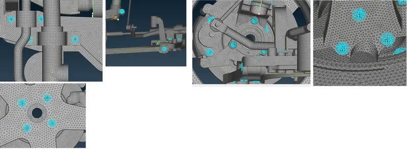
First, we generate RBE2 Connection then we join 2 RBE2 Connection with help of Two Node Command.
SYMMETRY OPERATION:
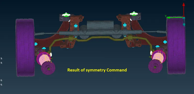
Here we perform Symmetry operation to save time, Effort and do the modelling precisely.
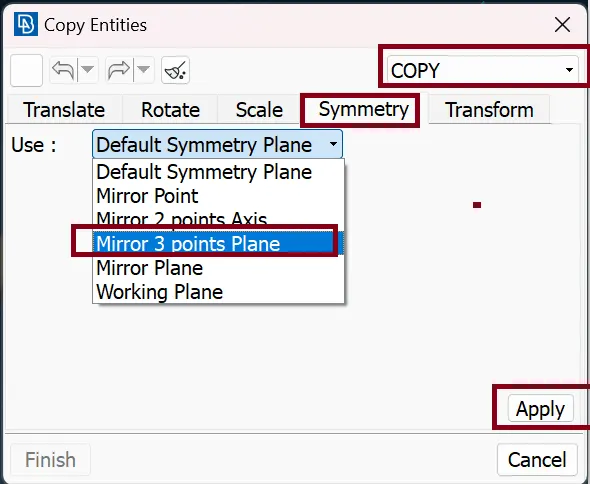
Command: Utilities >> Transform >> Copy >> Entities >> Select entire component (half) >> hit middle mouse click >> Symmetry >> Mirror 3 Points Plane >> Select 3 Point as per figure below >> Apply >> Finish.
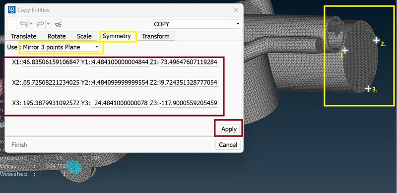
Finally we have..
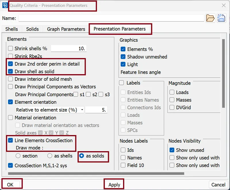
Representations:
Command : Utilities >> Quality Criteria >> Presentation Parameters >> edit the Card as per figure below >> Hit Apply >> ok.
LEARNING OUTCOMES
- How to fix the geometrical errors.
- How to extract the mid surface for the uniform thickness component by auto and manual methods.
- How to perform proper mesh flow in shell mesh.
- How to fix the errors in the mesh using various tools.
- How to define a volume & volume mesh with the TETRA FEM and TETRA rapid.
- How to defeature the area in order to avoid errors in meshing.
- How to fix the errors in the volume mesh.
- How to fix the dips and kinks in a volume mesh.
- How to do PBAR (Spring) connection.
- Learned to deploy the connections using the RBE2 many and two nodes.
- Learned how to mirror the component using the TRANSFORM tool symmetry option.
CONCLUSION
Finally, we done Meshing on the give suspension assembly according to the given quality criteria and mesh parameters. Use Appropriate connections to connect the suspension assembly and perform Symmetry command to reflect the half-finished model to the other side.
Drive link
SUSPENSION ASSEMBLY: https://drive.google.com/file/d/1717EIgfraXQn5oo9mcCwm_vQZg2ix-eQ/view?usp=share_link
***********************************************************************************************************************************************************************************************************************************************************************END