Duty Cycle
Aim:
- Why power electronics circuits are efficient? In practice, which types of losses occur in power electronics circuits?
- Using a suitable MATLAB model, show how duty cycle control signal can be generated for a simple power converter circuit?
- Make a comparison of square wave inverter output voltage with sine modulated one.
- Explain the difference between VFD and Vector control drive. Can we use VFD method for induction motor in EV application?
- 1. power electronics circuits:
- Power electronics is the study of switching electronic circuits in order to control the flow of electrical energy, its generation, transportation and applications. Power Electronics is the technology behind switching power supplies, power converters, power inverters, motor drives, and motor soft starters.Power electronics deals with the conversion and control of electrical energy with the help of power semiconductor devices that operate in a switching mode, and, therefore, efficiency of power electronic apparatus may approach as high as 98–99%.
- Power electronics is very important in modern high-efficiency energy processing systems, such as HVDC, SVC, flexible ac transmission system (FACTS) for active and reactive power flow control, uninterruptible power supply (UPS), and industrial process control with variable-frequency drives for improving productivity and quality of products in modern automated factories.
- Variable-frequency drives are now used extensively in pumps and compressor drives, paper and textile mill drives, subway and locomotive propulsion, electric and hybrid vehicles, elevators, metal rolling and textile mills, home appliances, machine tools, and robotics, variable-speed air conditioners, wind generation systems, ship propulsion. Power electronics plays a very important role in solving or mitigating our global warming problem, which is a very serious concern in our society.
- Losses in power electronics circuits:
- Basically, there are two types of losses occur in power electronics. They are,
- Conduction loss
- Switching loss
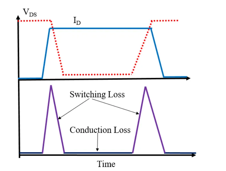
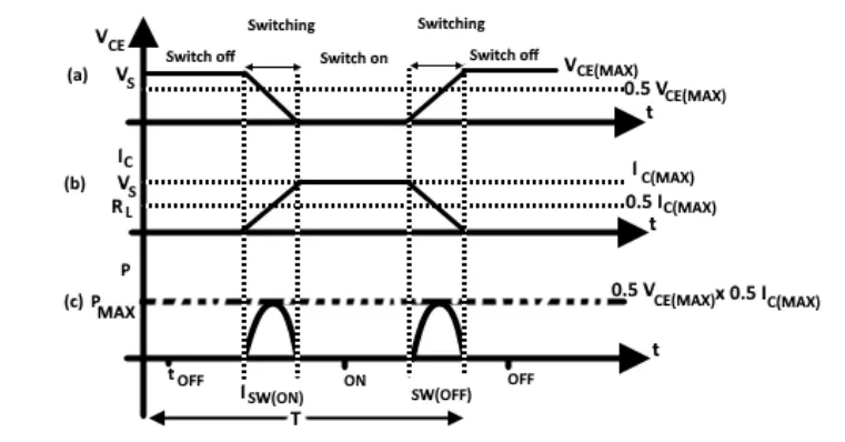
- Waveforms during switching operation:
- Voltage accross the switch
- Current throught the switch
- Power dissipated in the switch
- Conduction loss:
- Losses occur during the condition of electric power.
- `Power (P)= V*I`
- `Pavg= 1/t int(V*I) dt`
- where, `V=` Voltage (V)
`I=` current (A)
`t=`time period (sec)
- from ohm's law,`V=I*R implies I=V/R`
- `therefore Pavg= int (V^2on)/(Ron)`
`= (V^2RMS)/(Ron) or I^2 *Ron`
- Switching loss:
- Losses occur during the turn ON or turn OFF of switch. A real switch has switching losses because it cannot hange from the ON state to OFF state or vice versa instantaneously. switch takes a finate time to turn ON and turn OFF, these times not only introduce power dissipation but also limit the highest switching frequency possible.
- During Switch ON condition:
- current `i(t) = I/(t on).t`
- Voltage `V(t) = V(1-t/(t on))`
- Power `(P) = V*i`
`= (VI)/(t on)*[t-t^2/(t on)]`
- Energy loss (E_on): `int(V*i) dt= (VI)/(t on) *[(t ^2on)/2 - t^3/(3*t on)]`
- `= (V*I)/6*t on`
- During Switch OFF condition:
- current `i(t) = I/(t off).t`
- Voltage `V(t) = V(1-t/(t off))`
- Power `(P) = V*i`
`= (VI)/(t off)*[t-t^2/(t off)]`
- Energy loss (E_off): `int(V*i) dt= (VI)/(t off) *[(t ^2off)/2 - t^3/(3*t off)]`
- `= (V*I)/6*t off`
- Switching loss = E_on + E_off
- `therefore implies =(V*I)/6*[t on + t off]`
- Energy `(E) = P*t`
- Total switching power loss `(P_s):`
`P_s = E/t = f*E`
where, f= frequency (Hz)
- 2. Using a suitable MATLAB model, show how duty cycle control signal can be generated for a simple power converter circuit?
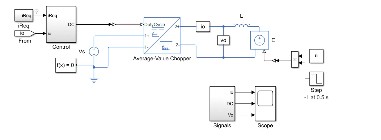
- Average-Value Chopper Control:
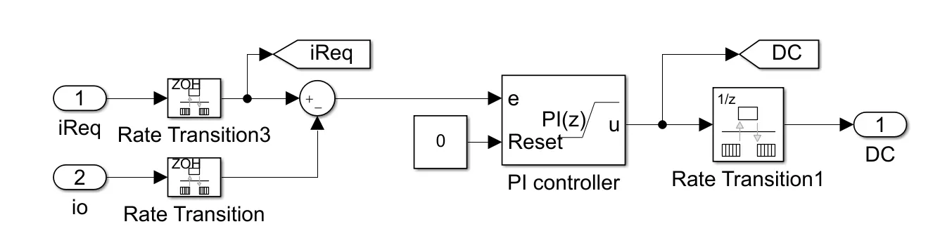
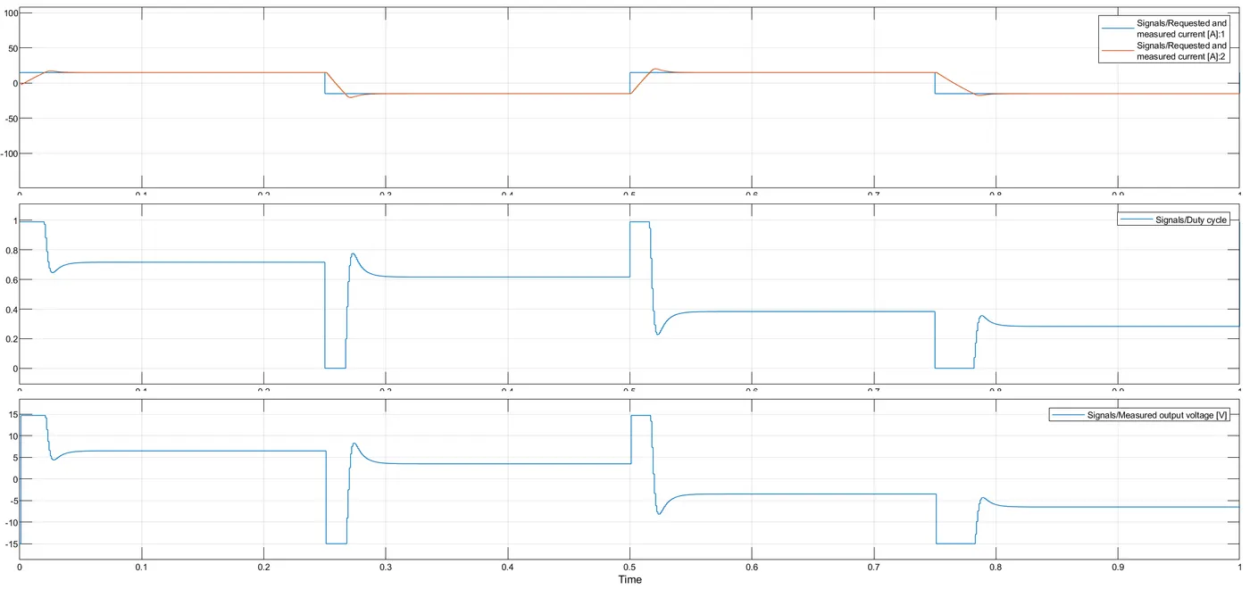
- This model shows how to control a four-quadrant chopper. The Control subsystem implements a simple PI-based control algorithm for controlling the output current. An average-value Chopper model is used to speed up the simulation. The simulation uses both positive and negative references. The total simulation time (t) is 1 s. At t = 0.5 s, the polarity of the load DC source E changes.
- Control subsystem:
Result:
- The plot below shows the requested and measured current for the test and the output voltage in the circuit.
- 3. comparison of square wave inverter output voltage with sine modulated one:
- Classification of Inverter:
- Inverter can be classified into many types based on output, source, type of load etc. Below is the complete classification of the inverter circuits:
- According to the Output Characteristic
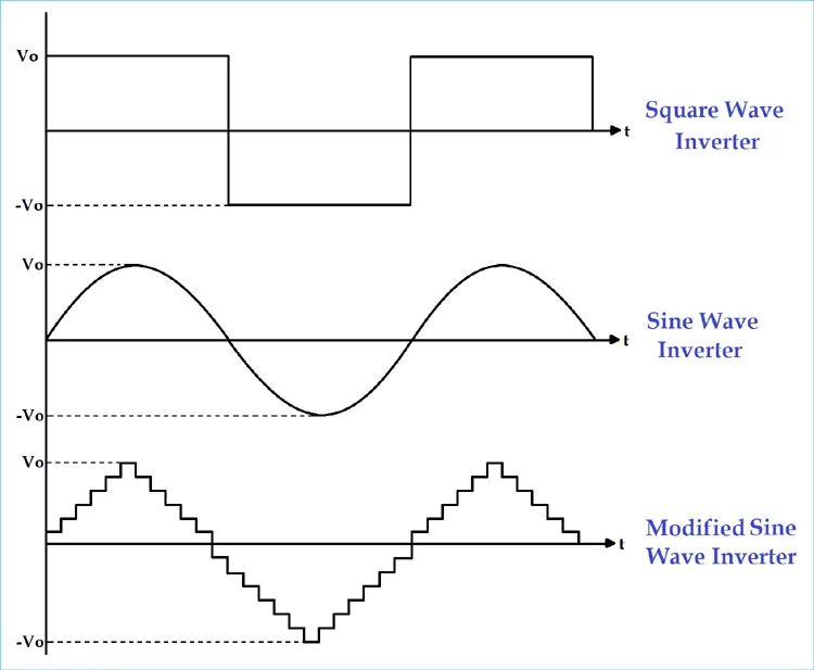
- Square Wave Inverter
- Sine Wave Inverter
- Modified Sine Wave Inverter
- a. Square wave inverter:
- The output waveform of the voltage for this inverter is a square wave. This type of inverter is least used among all other types of inverter because all appliances are designed for sine wave supply. If we supply square wave to sine wave based appliance, it may get damaged or losses are very high. The cost of this inverter is very low but the application is very rare. It can be used in simple tools with a universal motor.
- b. Sine wave:
- The output waveform of the voltage is a sine wave and it gives us a very similar output to the utility supply. This is the major advantage of this inverter because all the appliances we are using, are designed for the sine wave. So, this is the perfect output and gives guarantee that equipment will work properly. This type of inverters is more expensive but widely used in residential and commercial applications.
- c. Modified sine wave:
- The construction of this type of inverter is complex than simple square wave inverter but easier compared to the pure sine wave inverter. The output of this inverter is neither pure sine wave nor the square wave. The output of such inverter is the some of two square waves. The output waveform is not exactly sine wave but it resembles the shape of a sine wave.
- 4. Difference between VFD and Vector control drive.
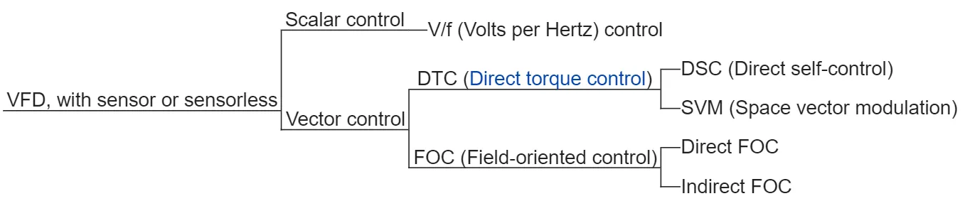
- Overview of key competing VFD control platforms:
- Variable-frequency drive (VFD):
-
VFD is one of the commonly used techniques for controlling the speed of an electric motor. In this technique, power electronic devices are used to vary the frequency of the input power to the electric motor by a technique called Pulse Width Modulation (PWM) and thereby controlling the speed of the motor.
VFD system, using PWM, is capable of adjusting both the speed and torque of an electric motor and therefore provides a continuous range of process speed control.
A Variable Frequency Drive system is also known as Adjustable Frequency Drive (AFD) or Variable Speed Drive (VSD) or Variable Voltage Variable Frequency (VVVF) Drive. It is a simple device that controls the voltage and frequency of the input power of a motor and therefore controls speed of the motor as well as the system being driven by the motor.
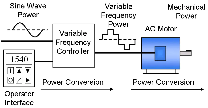
- A variable-frequency drive is a device used in a drive system consisting of the following three main sub-systems: AC motor, main drive controller assembly, and drive/operator interface.
- Benefits of VFD:
- The following are the benefits of using VFDs in HVAC systems. Other applications will also have a similar set of benefits.
- A typical HVAC system consists of fans, pumps, compressors, air handlers and chillers. All the motor related devices can have the following benefits when used with a variable speed drive system.
- Simple installation and maintenance.
- Low motor starting current.
- Energy savings.
- Reduced mechanical and thermal stress on motors and belts during start.
- High power factor and low KVA.
- Vector control drive (VCD):
- Vector control, also called field-oriented control (FOC), is a VFD control method in which the stator currents of a 3-phase AC Electric motor are identified as two orthogonal components that can be visualized with a vector. One component defines the magnetic flux of the motor, the other the torque. The control system of the drive calculates the corresponding current component references from the flux and torque references given by the drive's speed control.
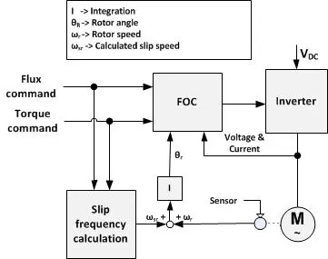
- Can we use VFD method for induction motor in EV application!
- VFD is mostly applicable for pumps and other small applications. In the VFD flux and current are coupled to each other. The efficiency of battery is low but in space vector pulse width modulation, the torque and flux are decoupled and also it can achive to reference voltage and small switching losses. The precession of EV can not be achieved. The efficiency of VFD is low thus, the overall efficiency of the vehicl is reduced.
- Hence, VFD method for Induction motor is not emplyed to EV application.
Reference: