Induction Motor
Aim:
- Discuss about the equivalent circuit network of induction motor MATLAB model.
- Calculate the ratio of starting torque at half voltage & frequency to rated values.
- Make a MATLAB script file which will plot speed torque characteristics for frequency control method.
- Explain in brief about operation of BLDC motor.
Software used:
- MATLAB R2020a
1. Equivalent Circuit of Induction Motor:
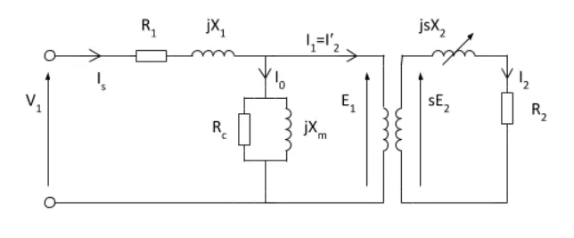
- In the equivalent circuit R1 represents, the resistance of the stator winding and X1 the stator leakage reactance (flux that does not link with the air gap and rotor). Magnetising reactance required to cross the air gap is represented by Xm and core losses (hysteresis and eddy current) by Rc.
- An ideal transformer of N1 and N2 turns respectively represents the air gap. For the rotor side, the induced emf is affected by the slip (as the rotor gains speed, slip reduces and less emf is induced). The rotor resistance and reactance are represented by R2 and X2; with X2 being dependant on the frequency of the inductor rotor emfs.
- The rotor circuit, the current I2 is given by: `I2=(E2)/(sqrt(((R2)/s)^2 + (X2)^2`
Slip:
- Induction motors are asynchronous. The stator magnetic field rotates at the motors synchronous speed (ns). The rotor can never rotate at synchronous speed, otherwise there would be no induced current. Typically the rotor full speed will between 2 and 6% that of the synchronous speed. The difference between the motors synchronous and actual asynchronous speed is known as the slip
- The difference between the motors synchronous speed (ns) and actual rotor speed (nr) is known as the slip (s).
- Slip can be expressed as either a fraction or percentage:
- `s=(ns-nr)/(ns)`
Frequency:
- From magnetic winding theory, the relationship between frequency in the stator (f), number of pole pairs (p) and the synchronous speed is given by:
- `f=omegams*p`
Simplified Equivalent Circuit of induction motor:
Description:
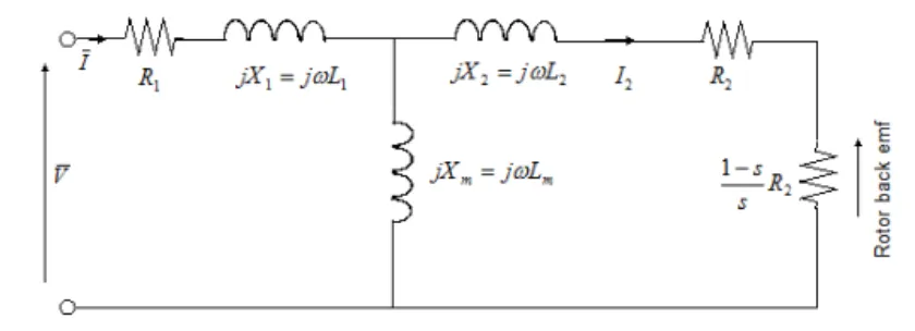
- The Simplified Induction Motor block represents the electrical and torque characteristics of an induction motor powered by an ideal AC supply. The following figure shows the equivalent circuit model of the Simplified Induction Motor block.
In the figure:
- R1 is the stator resistance.
- R2 is the rotor resistance with respect to the stator.
- X1 is the stator leakage reactance (flux that does not link with the air gap and rotor).
- Xm represents the Magnetising reactance required to cross the air gap.
- Rc represents core losses (hysteresis and eddy current).
- L1 is the stator inductance.
- L2 is the rotor inductance with respect to the stator.
- Lm is magnetizing inductance.
- s is the rotor slip.
- `bar V and barI` are the sinusoidal supply voltage and current phasors.
- Rotor slip s is defined in terms of the mechanical rotational speed ωm, the number of pole pairs p, and the electrical supply frequency ω by
-
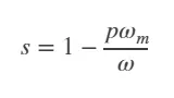
- This means that the slip is one when starting, and zero when running synchronously with the supply frequency.
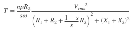
- For an n-phase induction motor the torque-speed relationship is given by:
-
where:
- `Vrms` is the line-neutral supply voltage for a star-configuration induction motor, and the line-to-line voltage for a delta-configuration induction motor.
- `n` is the number of phases.
- You can parameterize this block in terms of the preceding equivalent circuit model parameters or in terms of the motor ratings the block uses to derive these parameters.
- This block produces a positive torque acting from the mechanical C to R ports.
Thermal Ports:
- The block has two optional thermal ports, one per winding, hidden by default. To expose the thermal ports, right-click the block in your model, and then from the context menu select Simscape > Block choices > Show thermal port. This action displays the thermal ports on the block icon, and exposes the Temperature Dependence and Thermal Port parameters. These parameters are described further on this reference page.
- Use the thermal ports to simulate the effects of copper resistance losses that convert electrical power to heat. For more information on using thermal ports in actuator blocks, see Simulating Thermal Effects in Rotational and Translational Actuators.
Assumptions and Limitations:
- The block does not model the starting mechanism for a single-phase induction motor.
- When you parameterize the block by motor ratings, the block derives the equivalent circuit model parameters by assuming that the effect of the magnetizing inductance Lm is negligible, and the magnetizing inductance is not included in the simulated component.
2. Calculate the ratio of starting torque at half voltage & frequency to rated values.
Given parameters:
- No. phases: 3 phase
- Frequency: 50 Hz induction motor
- Stator Inductance X1 =0.1 ohm
- Rotor Inductance X2 = 0.1 ohm and
- Stator Resistance R1 =0.2 ohm
- Rotor Resistance R2 = 0.2 ohm
- operated at half of rated voltage and frequency.
Governing Equation:
- Torque:
`T=(3/(omega ms))*[(V^2*(R2)/s)/((R1+(R2)/s)^2+(X1+X2)^2)]`
where,
- `omega ms =` Synchronous Speed rad/sec
- R1= Stator Resistance
- R2= Rotor Resistance
- X1= Stator Inductance
- X2= Rotor Inductance
- s= Slip
- Rated Frequency `(f):` 50 Hz
- Half Rated Frequency `(f'):` 50/2 = 25 Hz
- Rated Synchronous Speed:
`omega ms= (120*f)/p`
`= (120*50)/p`
`= 6000/p`
- Half Rated Synchronous Speed:
-
`omega' ms= (120*f)/p`
`= (120*25)/p`
`= 3000/p`
- Rated Torque:
`T=(3/(omega ms))*[(V^2*R2)/((R1+(R2))^2+(X1+X2)^2)]`
`=(3/(omega ms))*[(V^2*0.2)/((0.2+(0.2)^2+(0.1+0.1)^2)]`
`= (3*V^2)/(omega ms)`
- Half Rated Torque:
`T'=1/2*(3/(omega ms))*[((V/2)^2*R2)/((R1+(R2))^2+(X1+X2)^2)]`
`=1/2*(3/(omega ms))*[(V^2*0.2)/((0.2+(0.2)^2+(0.1+0.1)^2)]`
`= (1.5*V^2)/(omega ms)`
- Ratio of Half Rated Torque & Rated Torque:
- `(T')/T``= (1.5*V^2)/(omega ms)/ (3*V^2)/(omega ms)`
- `= 1/2 = 0.5`
`therefore`the ratio of Starting torque to half rated torque is `1/2`
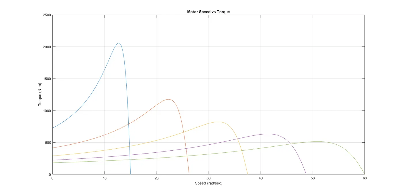
3. MATLAB script file which will plot speed - torque characteristics for frequency control method:
- Matlab Code:
clear all
close all
clc
%Inputs
%No.of poles (p)
p=4;
%Slip
s=linspace(0,1,100);
%Stator Resistance (R1)
R1=0.6;
% Rotor Resistance (R2)
R2=0.3;
% Stator Inductance (X1)
X1=1.4;
% Rotor Inductance (X2)
X2=0.5;
%Voltage per phase (V)
V=400/sqrt(3);
%frequency (f)
f=linspace(0.5,2,5);
for i=1:5
   %Synchronous Speed (Wms) rad/sec
   W_ms=(120*f(i))/p;
   for j=1:100
       %Torque (T) N-m
       Wm(j)=(1-s(j)).*(W_ms);%rotor speed calculation
       denom=((R1+((R2)./(s(j)))).^2)+((X1+X2)^2); %denominator in torque equation
       T(j)=((3/W_ms)*((V^2)*(R2)./s(j)./(denom)));
       T(1)=0;
   end

%Plotting
plot(Wm,T)
hold on
title('Motor Speed vs Torque')
xlabel('Speed (rad/sec)')
ylabel('Torque (N-m)')
grid on

end
Procedure:
- Initially the inputs (no.of ploes, slip, Stator Resistsnce, Rotor Resistance, Stator Inductance, Rotor Inductance, voltage and frequency) are defined.
- Slip and frequency is varies with linespace() command.
- using for loop Synchronous speed, motor/rotor speed and Torque is calculated for various values of slip & frequency.
- Then plotted the graph between Motor speed and Torque.
Results:
- Plot - Motor Speed vs Torque:
4. BLDC motor:
-
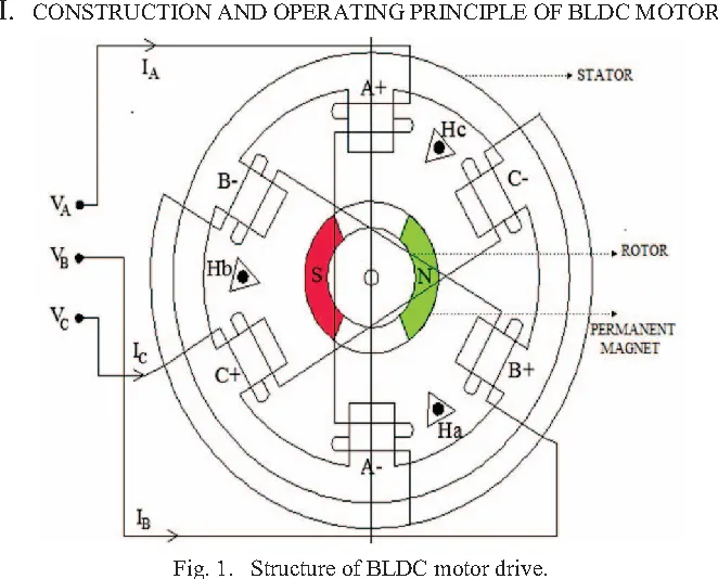
A Brushless DC motor (also known as a BLDC motor or BL motor) is an electronically commuted DC motor which does not have brushes. The controller provides pulses of current to the motor windings which control the speed and torque of the synchronous motor.
These types of motors are highly efficient in producing a large amount of torque over a vast speed range. In brushless motors, permanent magnets rotate around a fixed armature and overcome the problem of connecting current to the armature. Commutation with electronics has a large scope of capabilities and flexibility. They are known for smooth operation and holding torque when stationary.
Operation:
- In brushes motors, there are permanent magnets on the outside and a spinning armature which contains electromagnet is inside. These electromagnets create a magnet field in the armature when the power is switched on and help to rotate the armature.
- The brushes change the polarity of the pole to keep the rotation on of the armature. The basic working principle for the brushed DC motor and for brushless DC motor are same i.e. internal shaft position feedback.
- Brushless DC motor has only two basic parts: rotor and the stator. The rotor is the rotating part and has rotor magnets whereas stator is the stationary part and contains stator windings. In BLDC permanent magnets are attached in the rotor and move the electromagnets to the stator. The high power transistors are used to activate electromagnets for the shaft turns. The controller performs power distribution by using a solid-state circuit.
Advantages of a BLDC motor:
- Brushless motors are more efficient as its velocity is determined by the frequency at which current is supplied, not the voltage.
- As brushes are absent, the mechanical energy loss due to friction is less which enhanced efficiency.
- BLDC motor can operate at high-speed under any condition.
- There is no sparking and much less noise during operation.
- More electromagnets could be used on the stator for more precise control.
- BLDC motors accelerate and decelerate easily as they are having low rotor inertia.
- It is high performance motor that provides large torque per cubic inch over a vast sped rang.
- BLDC motors do not have brushes which make it more reliable, high life expectancies, and maintenance free operation.
- There is no ionizing sparks from the commutator, and electromagnetic interference is also get reduced.
- Such motors cooled by conduction and no air flow are required for inside cooling.
Disadvantages of a BLDC motor:
- BLDC motor cost more than a brushed DC motor.
- The limited high power could be supplied to BLDC motor, otherwise, too much heat weakens the magnets and the insulation of winding may get damaged.
Conclusion:
Hence,
- Discussed about the equivalent circuit network of induction motor MATLAB model.
- Calculated the ratio of starting torque at half voltage & frequency to rated values.
- created a MATLAB script file which will plot speed torque characteristics for frequency control method.
- Explained in brief about operation of BLDC motor.
Reference: