Week 8 - Simulation of a backward facing step in OpenFOAM
Aim:
To simulate an incompressible-laminar-viscous flow through the backward facing step geometry in OpenFOAM.
Mesh specification
- Number of blocks = 5
- Number of cells along the x direction (longer dimension) = 200
- Number of cells along the longer y direction = 20
Boundary condition specification
The domain specifications are provided in the following figure.
Geometry Creation:
Let us consider creating the geometry using 5 blocks as shown in the figure below so that it makes task easy to create a Blockmesh.
The Isometric View,
Now let’s, start indexing the Vertices on the Back side of the Blocks, Since openFoam uses C++ programming, we start the index from “0”.
Procedure:
1. In the blockMeshDict file will create the gemoetry and mesh as follows for Grading Factor (GF) = 1.
/*--------------------------------*- C++ -*----------------------------------*\
  =========                 |
  \\      /  F ield         | OpenFOAM: The Open Source CFD Toolbox
   \\    /   O peration     | Website:  https://openfoam.org
    \\  /    A nd           | Version:  8
     \\/     M anipulation  |
\*---------------------------------------------------------------------------*/
FoamFile
{
    version     2.0;
    format      ascii;
    class       dictionary;
    object      blockMeshDict;
}
// * * * * * * * * * * * * * * * * * * * * * * * * * * * * * * * * * * * * * //

convertToMeters 1;

vertices
(
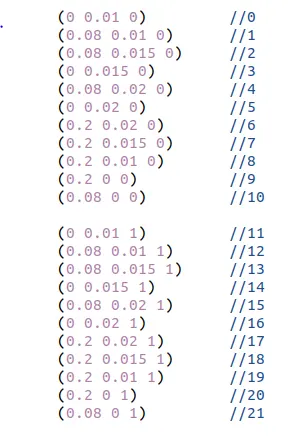
    (0 0.01 0)		//0
    (0.08 0.01 0)	//1
    (0.08 0.015 0)	//2
    (0 0.015 0)	//3
    (0.08 0.02 0)	//4
    (0 0.02 0)		//5
    (0.2 0.02 0)	//6
    (0.2 0.015 0)	//7
    (0.2 0.01 0)	//8
    (0.2 0 0)		//9
    (0.08 0 0)		//10

    (0 0.01 1)		//11
    (0.08 0.01 1)	//12
    (0.08 0.015 1)	//13
    (0 0.015 1)	//14
    (0.08 0.02 1)	//15
    (0 0.02 1)		//16
    (0.2 0.02 1)	//17
    (0.2 0.015 1)	//18
    (0.2 0.01 1)	//19
    (0.2 0 1)		//20
    (0.08 0 1)		//21

);

blocks
(
    hex (0 1 2 3 11 12 13 14) (80 5 1) simpleGrading (1 1 1)		// Block 1
    hex (3 2 4 5 14 13 15 16) (80 5 1) simpleGrading (1 1 1)		// Block 2
    hex (2 7 6 4 13 18 17 15) (120 5 1) simpleGrading (1 1 1)		// Block 3
    hex (1 8 7 2 12 19 18 13) (120 5 1) simpleGrading (1 1 1)		// Block 4
    hex (10 9 8 1 21 20 19 12) (120 10 1) simpleGrading (1 1 1)		// Block 5
);

edges
(
);

boundary
(
    inlet
    {
        type patch;
        faces
        (
            (0 11 14 3) 		// Inlet
            (3 14 16 5)			// Inlet
        );
    }
    outlet
    {
        type patch;
        faces
        (
            (9 8 19 20)			// Outlet
            (8 7 18 19)			// Outlet
            (7 6 17 18)			// Outlet
        );
    }
    frontAndBack
    {
        type empty;
        faces
        (
            (14 11 12 13)		// Front
            (16 14 13 15)		// Front
            (15 13 18 17)		// Front
            (13 12 19 18)		// Front
            (21 20 19 12)		// Front
            (2 3 5 4)			// Back
            (1 0 3 2)			// Back
            (2 4 6 7)			// Back
            (1 2 7 8)			// Back
            (10 1 8 9)			// Back
        );
    }
    Noslipwalls
    {
    	type wall;
    	faces
    	(
	       (5 16 15 4)		// Top
	       (4 15 17 6)		// Top
	       (10 21 12 1)		// Step side
	       (0 1 12 11)		// Bottom
	       (20 21 10 9)		// Bottom
    	);
    }
);

mergePatchPairs
(
);

// ************************************************************************* //
- First will define the vertices of this five blocks, here it is total 22 vertice.
Next will create the blocks with meshsize.
To create the 1st Block for this case,
Meshing:
Now to mesh the geometry fill in the number of cells in x, y and z direction inside the second parenthesis of the hex command,
hex (0 1 2 3 11 12 13 14) (80 5 1) simpleGrading (1 1 1)
Similarlly to create other blocks, (2, 3, 4, 5) respectively.
hex (3 2 4 5 14 13 15 16) (80 5 1) simpleGrading (1 1 1)
hex (2 7 6 4 13 18 17 15) (120 5 1) simpleGrading (1 1 1)
hex (1 8 7 2 12 19 18 13) (120 5 1) simpleGrading (1 1 1)
hex (10 9 8 1 21 20 19 12) (10 5 1) simpleGrading (1 1 1)
since this is a 2D problem, increasing the number of cells in the z direction, doesn’t make sense. To view the mesh in paraFoam, select the surface with edges option and view the mesh.
Similarly to refine the mesh near the walls of the geometry, we need to play around with the numbers in the third parenthesis.
- Next will define the Boundary conditions.
- Boundary Conditions:
Before we run the simulations, we need to specify the initial and boundary conditions.
- To define the faces, we need to specify the right order of vertex indices.
- To View the geometry that have created, clear out all the entries inside the boundary section of the blockMeshDict file and execute the blockMesh command in the terminal.
- After defining the boundaries correctly, to check if you have given defined them correctly, execute the blockMesh command in the terminal.Now open paraFoam, select all the patches and click apply. You will now be able to see the boundary conditions that have been applied to the geometry.
In the controlDict file will edit the time in such a way that the CFL<1.
/*--------------------------------*- C++ -*----------------------------------*\
  =========                 |
  \\      /  F ield         | OpenFOAM: The Open Source CFD Toolbox
   \\    /   O peration     | Website:  https://openfoam.org
    \\  /    A nd           | Version:  8
     \\/     M anipulation  |
\*---------------------------------------------------------------------------*/
FoamFile
{
    version     2.0;
    format      ascii;
    class       dictionary;
    location    "system";
    object      controlDict;
}
// * * * * * * * * * * * * * * * * * * * * * * * * * * * * * * * * * * * * * //

application     icoFoam;

startFrom       startTime;

startTime       0;

stopAt          endTime;

endTime         0.5;

deltaT          0.0005;

writeControl    timeStep;

writeInterval   20;

purgeWrite      0;

writeFormat     ascii;

writePrecision  6;

writeCompression off;

timeFormat      general;

timePrecision   6;

runTimeModifiable true;


// ************************************************************************* //
In the 'p' file will define the pressure at inlet, outlet, noslip, front and back faces.
/*--------------------------------*- C++ -*----------------------------------*\
  =========                 |
  \\      /  F ield         | OpenFOAM: The Open Source CFD Toolbox
   \\    /   O peration     | Website:  https://openfoam.org
    \\  /    A nd           | Version:  8
     \\/     M anipulation  |
\*---------------------------------------------------------------------------*/
FoamFile
{
    version     2.0;
    format      ascii;
    class       volScalarField;
    object      p;
}
// * * * * * * * * * * * * * * * * * * * * * * * * * * * * * * * * * * * * * //

dimensions      [0 2 -2 0 0 0 0];

internalField   uniform 0;

boundaryField
{
    inlet
    {
        type            zeroGradient;
    }
    outlet
    {
    	type 		 fixedValue;
    	value		 uniform 0;
    }

    noSlipWalls
    {
        type            zeroGradient;
    }

    frontAndBack
    {
        type            empty;
    }
}

// ************************************************************************* //
In the 'U' file will updated the velocity at inlet, outlet, noslip, front and back faces.
/*--------------------------------*- C++ -*----------------------------------*\
  =========                 |
  \\      /  F ield         | OpenFOAM: The Open Source CFD Toolbox
   \\    /   O peration     | Website:  https://openfoam.org
    \\  /    A nd           | Version:  8
     \\/     M anipulation  |
\*---------------------------------------------------------------------------*/
FoamFile
{
    version     2.0;
    format      ascii;
    class       volVectorField;
    object      U;
}
// * * * * * * * * * * * * * * * * * * * * * * * * * * * * * * * * * * * * * //

dimensions      [0 1 -1 0 0 0 0];

internalField   uniform (0 0 0);

boundaryField
{
    inlet
    {
        type            fixedValue;
        value           uniform (1 0 0);
    }
    outlet
    {
    	type		zeroGradient;

    }

    noSlipWalls
    {
        type            noSlip;
    }

    frontAndBack
    {
        type            empty;
    }
}

// ************************************************************************* //
2. For creating a mesh finer at the walls including the step side walls with GF=0.2:
blocks
(
    hex (0 1 2 3 11 12 13 14) (80 5 1) simpleGrading (0.2 5 1)		// Block 1
    hex (3 2 4 5 14 13 15 16) (80 5 1) simpleGrading (0.2 0.2 1)	// Block 2
    hex (2 7 6 4 13 18 17 15) (120 5 1) simpleGrading (5 0.2 1)		// Block 3
    hex (1 8 7 2 12 19 18 13) (120 5 1) simpleGrading (5 5 1)		// Block 4
    hex (10 9 8 1 21 20 19 12) (120 10 1) simpleGrading (5 5 1)		// Block 5
);
The sample grading is edited according to make walls finer. And the 'delta T' is reduced by 10 times to maintain the CFL number less than 1.
Commands used in this project:
- cd $FOAM_TUTORIALS to open inbuilt OpenFoam's tutorial directory.
- cd to change directory
- cd.. to return in previous directory
- gedit to edit (text document) file
- cp -r to copy whole directory
- ls to show list of contents (files, directories) inside directory
- run to open OpenFoam's run directory
- blockMesh to start meshing
- icoFoam to start simulation using icofoam slover
- paraFoam to post-process data using paraview.
Simulation steps:
- Open the Terminal in Ubuntu operating system.
- Type 'cd $FOAM_TUTORIALS' and it will take you into inbuilt tutorial directory of the OpenFoam software.
- By typing 'cd incompressible' go to the incompressiblle directory inside tutorials.
- Again type 'cd icoFoam' this will take you to icofoam directory inside tutorials.
- Again, change the directory to cavity by typing 'cd cavity'.
- Now copy directory file of cavity to run directory by using 'cp -r cavity/ $FOAM_RUN/cavity_test' command.
- Now type 'run' which will take you directly to 'run' folder.
- Change the directory to system by using 'cd cavity/system' command. And type 'ls' to list out the files in system directory.
- In 'system-directory' we can see four files i.e.; blockmeshDict, controlDict, fvSchemes and fvSolution.
- Type 'gedit blockMeshDict' to edit the file, here we can create the geometry and define the mesh and provide the boundary conditions.
- Simillar edit 'controlDict' file by using 'gedit controlDict' command, this file controls our simulation by providing time limit, this file includes stsrt time, end time, no.of time intervals and Deltat.
- Always remember that the Courant number (CF condition) should be less than 1 (CFL<1) for stable solution, so choose Deltat & values accordingly.
- Return to the cavity directory by using command 'cd..'.
- To provide initial conditions change directory "0". Edit the "P" and "U" files which are respectively includes initial pressure and initial velocity conditions. Edit these files by using 'gedit' command.
- Now return to cavity_test directory after editing all above files as per problem data.
- Type 'blockmesh' command and hit enter. Blockmesh command gives us well structured mesh. If there has any error occurs while running file then check blockmeshDict file and try to create mesh again. If meshing is done properly without error then type 'icoFoam' command to start solving simulation by using icoFoam solver.
- After completion of all above steps without error, let's start for post processing by typing 'paraFoam' command.
- Next after select the plot over line, click apply and input the right values of (x,y,z) coordinate to position the probe, just after the step. After positioning the probe, scroll down further until you find a checklist to select the parameter you want to plot along the line probe.
Hit apply to get the parameter plotted along the line probe.
OpenFoam has feature of grading factor (cell expansion) for each direction in the block. This function enables mesh creation to be graded or refined in specified direction. The ratio of the width of the last cell along one edge of a block to the width of the same edge is called cell expansion ratio.
i.e.; Grading factor = Grading size of final cell/Grading size of first cell.
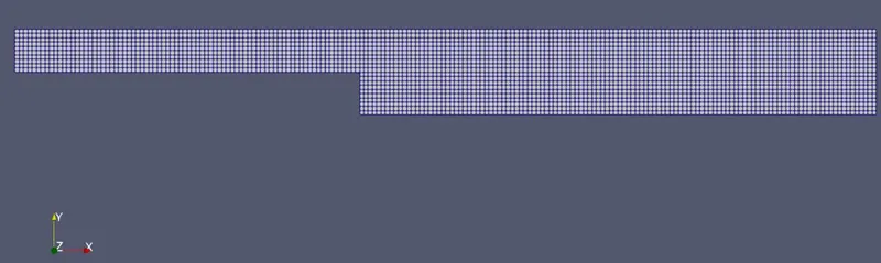
- As the grading factor given as 1, the mesh is creted equally along the plain.
- Velocity profile:
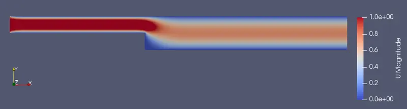
- Velocity plot at 0.085 m from the inlet of the geometry.
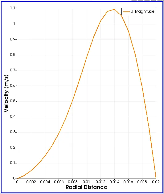
- Pressure profile:
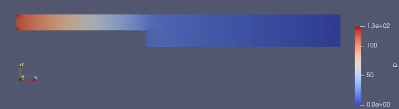
- Pressure plot at 0.085 m from the inlet of the geometry.
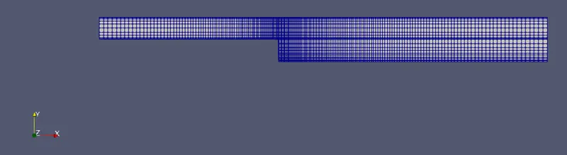
- Mesh is finer at the walls including step side.
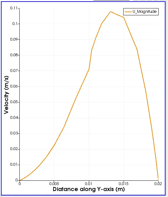
- Velocity profile:
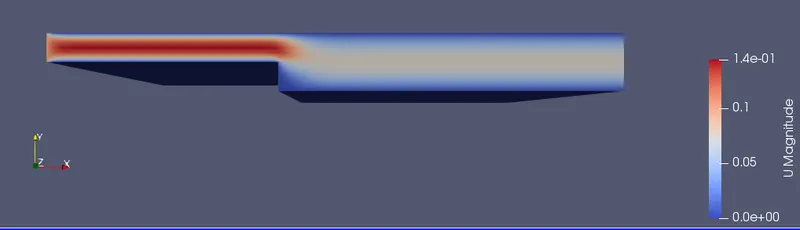
- Velocity plot at 0.085 m from the inlet of the geometry.
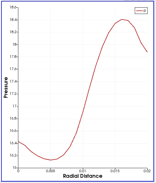
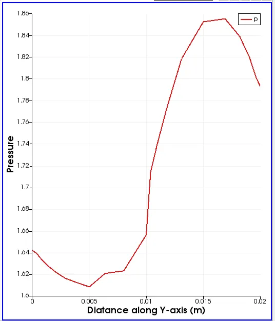
- Pressure profile:
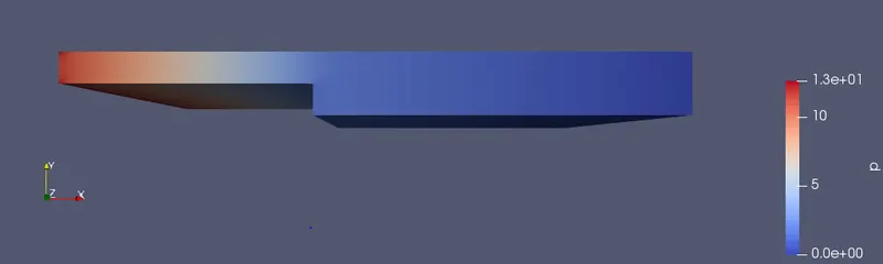
- Pressure plot at 0.085 m from the inlet of the geometry.
Observation:
- From observation of simulation results of both for Grading Factor =1 and 0.2, as the results are finer for GF=0.2.
- Velocity and Pressure curves are smoother with the GF=1 compaired to GF=0.2, but the results are accurate with GF=0.2.
- Finally, I conclude that to get the more accurete results, use finer mesh.