Control logic of a “washing machine” using Stateflow and “Gear shift”
Aim:
- Implement control logic of a “washing machine” using Stateflow.
- Make a Simulink chart for the “Gear shift” logic.
Software used:
MATLAB R2020a_Simulink
Theory:
1. Given conditions for "washing machine" Stateflow:
- If the power supply is available, the system gets activated.
- If the Water supply is not available, stop the process & indicate through the LED.
- Soaking time should be 200s followed by Washing time of 100s.
- Then rinsing happens for the next 20s & dryer runs for 50s
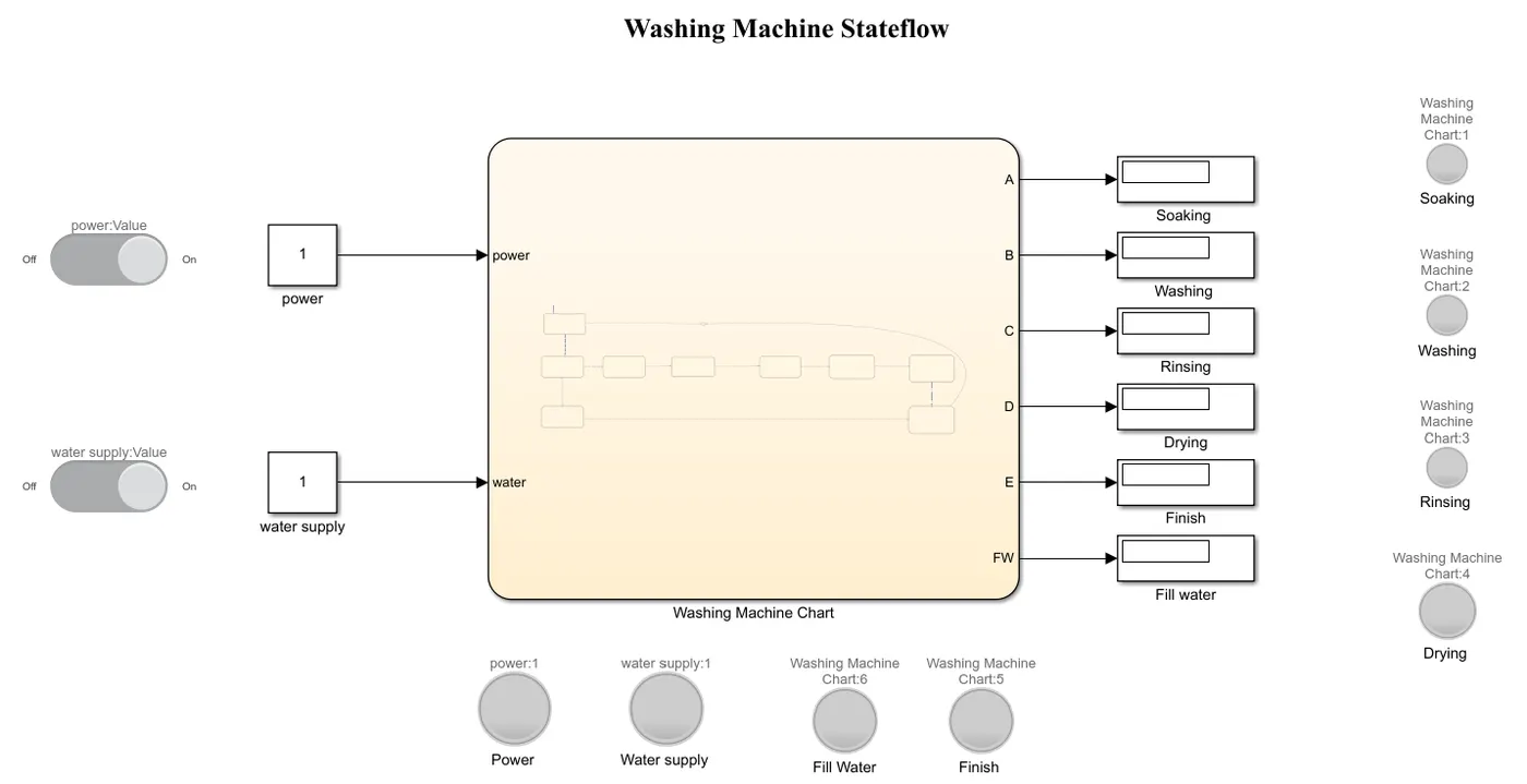
Washing Machine Stateflow chart:
Procedure:
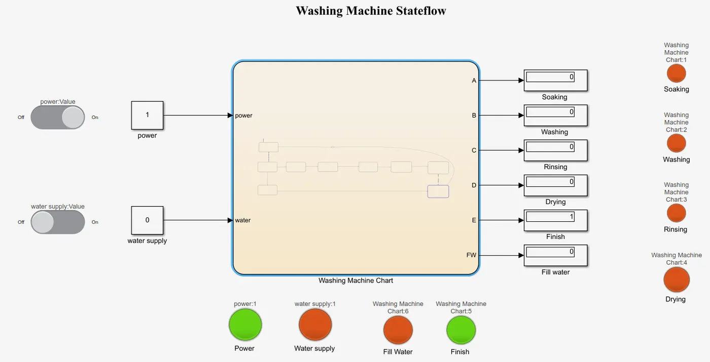
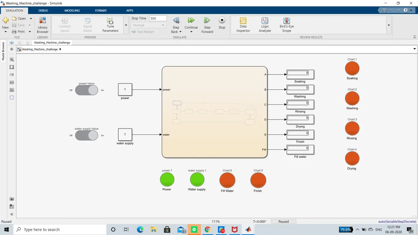
- Initially, the Inputs, power & water supply are connected to the chart, through slider switches by initiating constant values 0 and 1 as a condition for ON and OFF.
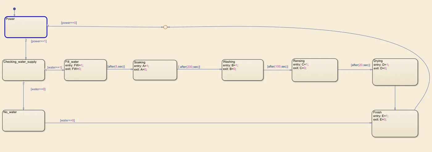
- In the chart, the flow process is initiated as per the given conditions.
Flow_1: Power & Water supply - checking water supply(If power is ON) - Filling water(If the water supply is ON) - Soaking - Washing - Rensing - Drying - Finish.
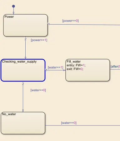
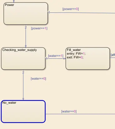
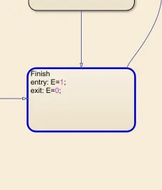
Flow_2: Power & Water supply - checking water supply(If power is ON) - No_water(If water supply if OFF) - Finish.
By using junction box will repeat the process after Finish/End
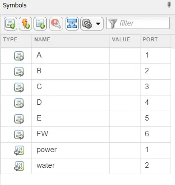
- The outputs are specified as Fill water(FW), Soaking(A), Washing(B), Rensing(C), Drying(D), Finish(E) and displayed the condition and LEDs.
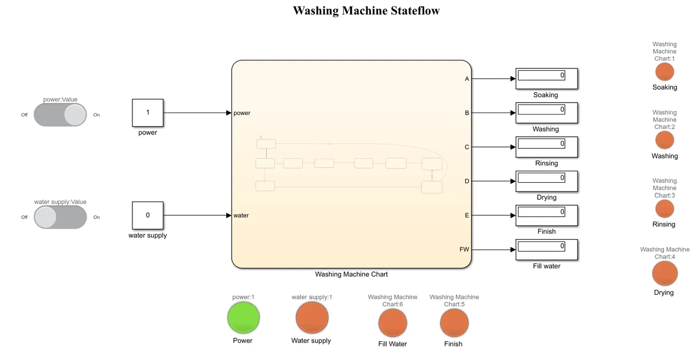
- If the condition is satisfied the LEDs show a "Green" color, else a "Red" color.
Stateflow process:
- When the only power source is ON & the water supply is OFF.
If the water supply is OFF the flow will get terminates after checking the water supply and then the process gets END.
1 2
3
- When the both Power and water supply is ON
1 2
3 4
5 6
worksheet:
2. Given conditions to make a Simulink chart for the "Gear Shfit"
Speed Range(kmph) Gear No.
0 to 15 1
16 to 25 2
26 to 40 3
41 to 60 4
Above 61 5
Gear Shift chart:
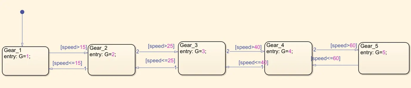
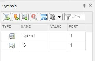
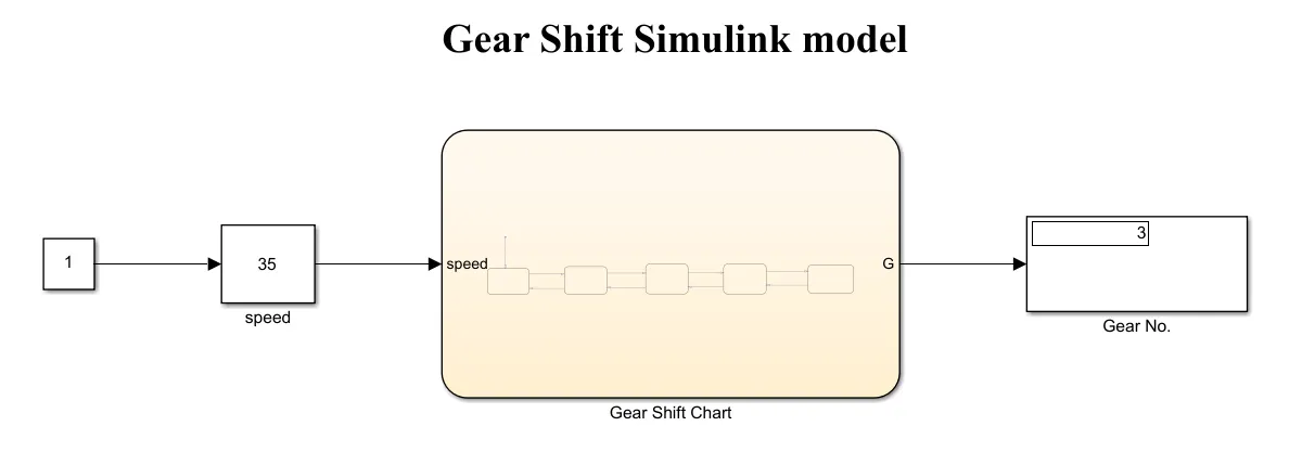
- When the speed is at 35KMPH
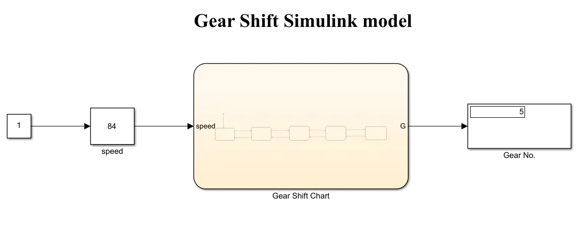
- When the speed is at 84KMPH
worksheet:
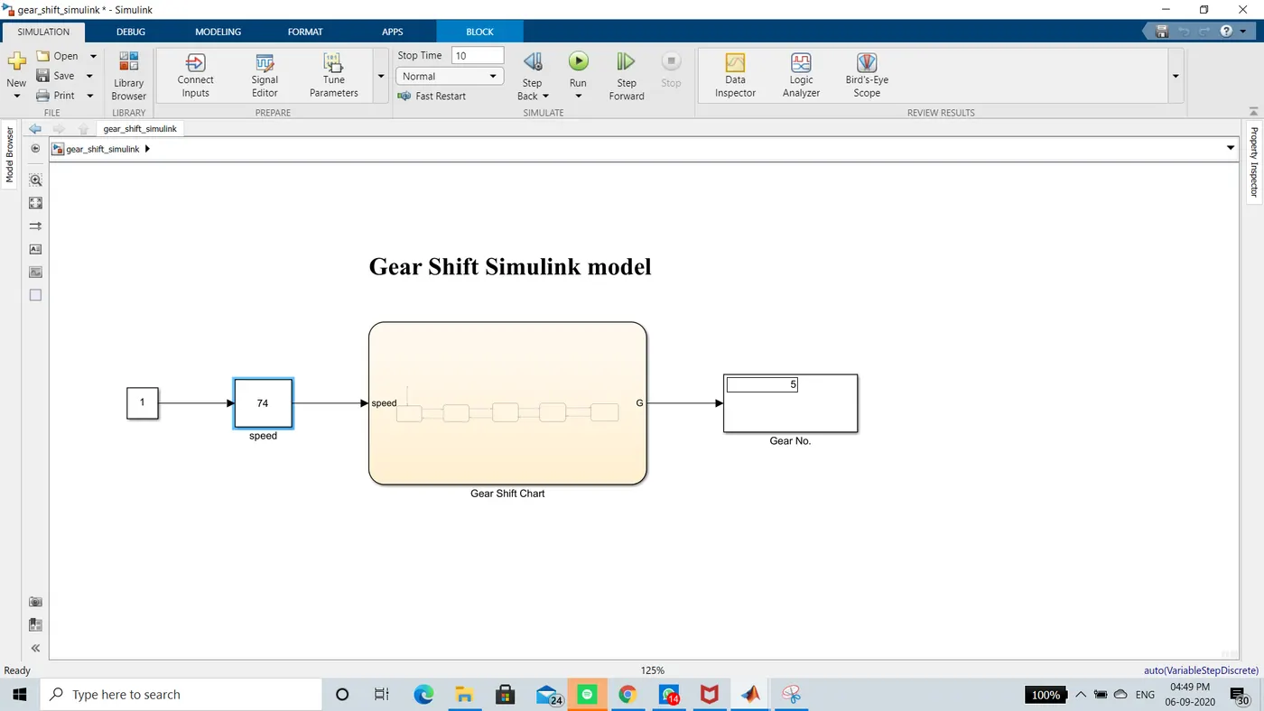
Blocks used:
constant: To input to slider gain
Slider gain: To change the speed of the vehicle
Chart: To create Gear shift flow
Display: To view the gear number.
Flow process:
Constant - Slider gain - Gear shift chart (Gear1, Gear2, Gear3, Gear4, Gear5) - Gear Number.
By changing the speed in the slider gain the gear number changes by following the flow process defined in the chart.
Conclusion:
Hence,
- Implemented the control logic of a “washing machine” using Stateflow.
- Created a Simulink chart for the “Gear shift” logic.