Week 6 Fuel cell powered vehicle model
Aim:
To Make a MATLAB model of fuel cell powered electric vehicle.
Introduction:
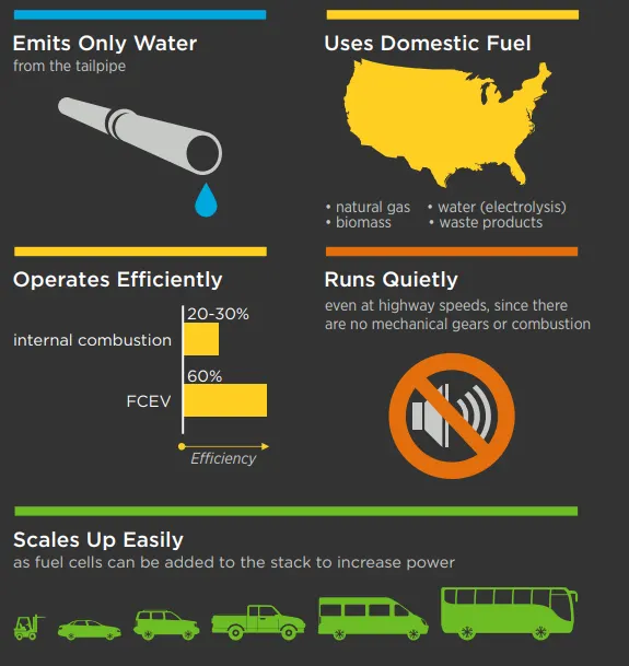
Fuel cell electric vehicles (FCEVs) are powered by hydrogen. They are more efficient than conventional internal combustion engine vehicles and produce no tailpipe emissions—they only emit water vapor and warm air.
FCEVs use a propulsion system similar to that of electric vehicles, where energy stored as hydrogen is converted to electricity by the fuel cell. Unlike conventional internal combustion engine vehicles.
Working of Fuel cell:
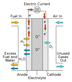
The most common type of fuel cell for vehicle applications is the polymer electrolyte membrane (PEM) fuel cell. In a PEM fuel cell, an electrolyte membrane is sandwiched between a positive electrode (cathode) and a negative electrode (anode). Hydrogen is introduced to the anode, and oxygen (from air) is introduced to the cathode. The hydrogen molecules break apart into protons and electrons due to an electrochemical reaction in the fuel cell catalyst. Protons then travel through the membrane to the cathode.
The electrons are forced to travel through an external circuit to perform work (providing power to the electric car) then recombine with the protons on the cathode side, where the protons, electrons, and oxygen molecules combine to form water.
MATLAB Model of Fuel Cell powered EV:
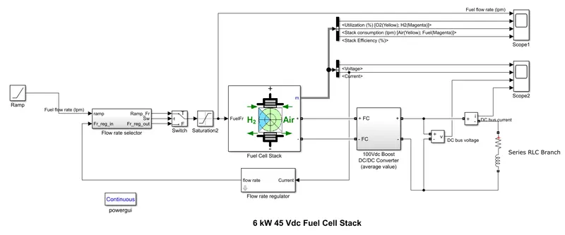
Here the fuel stack cell is loaded to the simple RL block through DC/DC converter to meet the required voltage of the load. The fuel flow rate is controlled by the switch from the ramp input. The Volatge and current generated by the fuel cell is applied to the load.
Ramp parameters:
| slop | 10 |
| flow time | 10 |
Fuel Cell Stack:
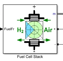
The Fuel Cell Stack block implements a generic model parameterized to represent most popular types of fuel cell stacks fed with hydrogen and air.
The block represents two versions of the stack model: a simplified model and a detailed model. You can switch between the two models by selecting the level in the mask under Model detail level in the block dialog box.
The model represents a particular fuel cell stack operating at nominal conditions of temperature and pressure. The parameters of the equivalent circuit can be modified based on the polarization curve obtained from the manufacturer datasheet. You just have to input in the mask the value of the voltage at 0 and 1 A, the nominal and the maximum operating points, for the parameters to be calculated. A diode is used to prevent the flow of negative current into the stack.
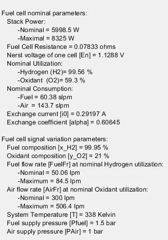
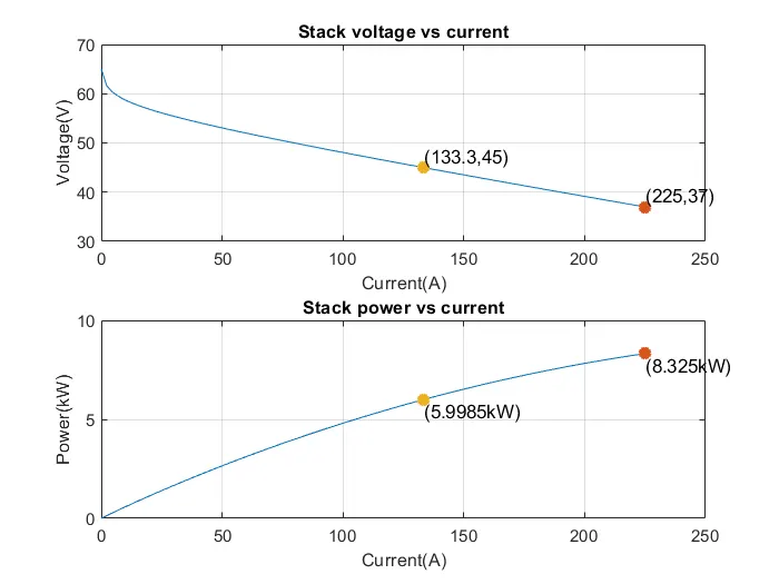
This plot indicated power, voltage and current characteristics of fuel cell.
Flow rate selector sub system:
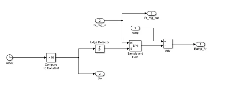
In this the ramp signal and sample and hold (S/H) are added and provides output.
Initially the constant to compare block compares the starting time and provide signal to the edge detector, it compare present input value (Boolean 1/0) to previous value to detect a change (signal edge). The output is a needle impulse (boolean 1) signal when the specified edge type (Rising, Falling, or Either) is detected. Here I selected to "Rising".
DC/DC Converter sub system (100Vdc Boost ):
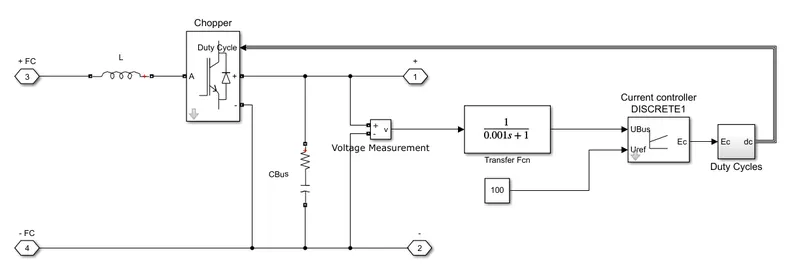
Blocks used for the DC/DC power converter are,
Series RLC Load Block: Implements a series branch of RLC elements. Here, I selected L type branch for Chopper input and RC is connected at the output terminals of chopper.
Chopper Block: This model implements an average-value buck converter."Duty Cycle" contains the duty cycle of the internal IGBT device.
Voltage measurement Block: To measure the voltage.
Transfer function is `1/(0.001s+1)`
Current controller DISCRETE:
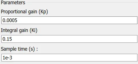
Duty cycle subsystem:
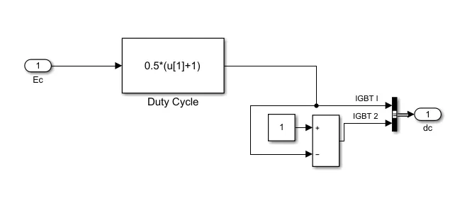
The duty cycle output is controlled by the chopper.
Flow rate Parameters:
| No.of cells | 65 |
| Nominal Hydrogen utilization (%) | 99.56 |
| Operating temperature | 65 C |
| Fuel pressure | 1.5 bar |
| H2 composition (%) | 99.95 |
Description:
The nominal Fuel Cell Stack voltage is 45Vdc and the nominal power is 6kW. The converter is loaded by an RL element of 6kW with a time constant of 1 sec. During the first 10 secs, the utilization of the hydrogen is constant to the nominal value (Uf_H2 = 99.56%) using a fuel flow rate regulator. After 10 secs, the flow rate regulator is bypassed and the rate of fuel is increased to the maximum value of 90 lpm in order to observe the variation in the stack voltage. That will affect the stack efficiency, the fuel consumption and the air consumption.
Fuel cell voltage, current, DC/DC converter voltage and DC/DC converter current signals are available on the Scope2. Fuel flow rate, Hydrogen and oxygen utilization, fuel and air consumption, and efficiency are available on the Scope1.
Simulation:
At t = 0 s, the DC/DC converter applies 100Vdc to the RL load (the initial current of the load is 0A). The fuel utilization is set to the nominal value of 99.56%. The current increases to the value of 133A. The flow rate is automatically set in order to maintain the nominal fuel utilization. Observe the DC bus voltage (Scope2) which is very well regulated by the converter. The peak voltage of 122Vdc at the beginning of the simulation is caused by the transient state of the voltage regulator.
At t = 10 s, the fuel flow rate is increased from 50 liters per minute (lpm) to 85 lpm during 3.5 s reducing by doing so the hydrogen utilization. This causes an increasing of the Nernst voltage so the fuel cell current will decrease. Therefore the stack consumption and the efficiency will decrease (Scope1).
Results:
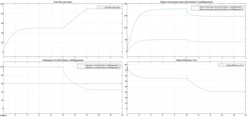
- Fuel flow rate (lpm): fuel flow rate is set to 90 lpm as a upper limit. The fuel is flowing as per the ramp parameters. Initially flow is increased to 50 lmp less than 5 sec and kept constant till 10 sec and then increased rapidly till 13.5 sec and set constant.
- Oxygen is utilized 100% till 10 sec and then gradually reduced till 14sec and set constant rest.
- Stack consumption of air is higher than fuel. The air is consumed more than 150 lpm where as fuel is less than 50 lpm.
- The stack efficiency decreased t 30%.
- As the fule flow changes after 10 sec, the stack consumption of fuel and air is reduced after 10 sec. and also stack efficiency is reduced to 30%.
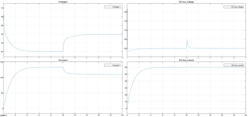
- Voltage of fuel cell is increased to more than 65V at the initial and then exponentially reduced and adjusted to 45V till 10sec and then suddenly increased to 55V.
- As Current is inversly proportional to the voltage, The current is exponentially increases to the value of 133A, and reduced after fuel flow change.
- DC converter bus voltage is got spike to 120+ V initially, and rest of the cycle is arround 100V. At the 10th sec went small spike 105V.
- DC bus current is 60A.
Benifits of FCEVs:

References: