Project-1: Powertrain for aircraft in runways
Aim:
- Search and list out the total weight of various types of aircrafts.
- Is there any difference between ground speed and air speed?
- Why is it not recommended to use aircraft engine power to move it on the ground at Airport?
- How an aircraft is pushed to runway when its ready to take off?
- Learn about take off power, tyre design, rolling resistance, tyre pressure, brake forces when landing.
- With necessary assumptions, calculate the force and power required to push / pull an aircraft by a towing vehicle.
-
Design an electric powertrain with type of motor, it’s power rating, and energy requirement to fulfill aircraft towing application. Estimate the duty cycle range to control the aircraft speed from zero to highest. Make all required assumptions. Prepare a table of assumed parameters. Draw a block diagram of powertrain.
- Search and list out the total weight of various types of aircrafts.
- Classification of Aircrafts:
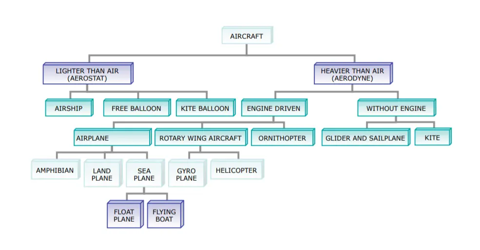
- Aircrafts are basically classified into 2 types:
- Lighter than Air (Aerostat):
Aerostats are capable of lifting a payload of 3,000 pounds (1,400 kg) to an altitude of more than 4.5 kilometres (2.8 mi) above sea level.
eg., Airship, Free Balloon, Kite Balloon, Hot Air Balloon.
- Air Balloons work on the principe of Buoyancy. Buyoancy is an upward force exerted by a fluid that opposes the weight of an immersed object.
- The two gases historically used in airships are Hydrogen and Helium. Hyderagen is less dense so it has a bit more lift, It is also considerable less expensive.
- As Hydrogen is highly flammable all contemporary airship use Helium.
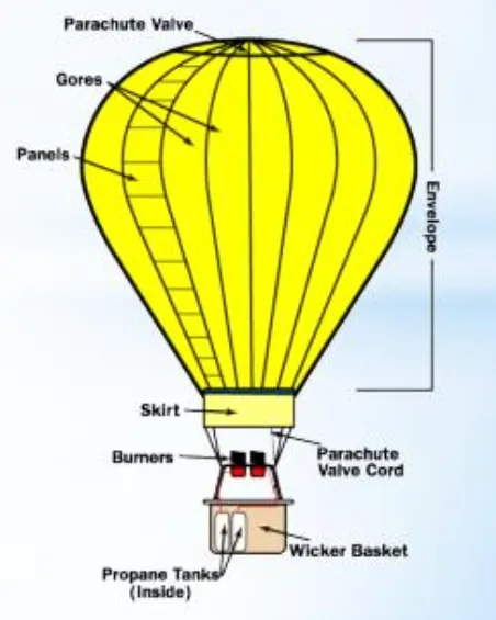
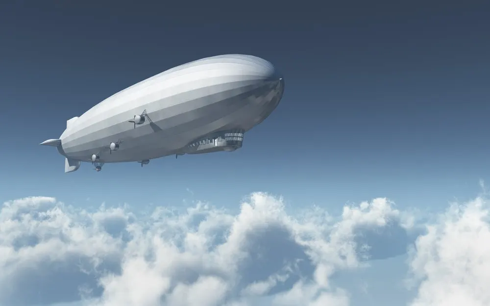
Hot Air Balloon Airship
- Heavier than Air (Aerodyne):
Heaver than Air Aircrafts are further classified into 2 types,
- Without - Engine Drive & With - Engine drive.
- A Heavier than Air Aircrafts uses a combination of four major forces namely Thrust, Drag, Lift and Weight to propell and balance itself in the air.
- Sailplanes or gliders:
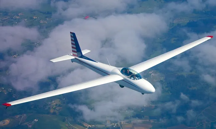
- Gliders are Powered only by gravity and air currents, these gliders move silently through the sky, often for hours at a time. Because they have no engines, gliders or sailplanes can be thought of as pure flying vehicles, staying aloft by balancing the forces of gravity, lift, drag, and thrust.
- Sailplanes or gliders as they are often referred to, come in all shapes, and sizes. There are two place trainers, single place, and even three place craft. Sailplanes are made from aluminum, wood, or a special fabric stretched over steel tubing. Some sailplanes are extremely refined, designed for maximum performance and constructed from exotic composite materials while others are designed for training new pilots necessitating rugged economy.
- Max. Weight: 1157 lbs
Empty Weight: 530 lbs
- Weights of various types of aircrafts:
Fighter aircraft:
| Specifications | Fighters | ||||||||||
|---|---|---|---|---|---|---|---|---|---|---|---|
|
F-15K |
F-15C | MiG-29K | MiG-29B | JF-17 | J-10 | F-35A | F-35B | F-35C | F-22 |
LCA Mk-1 |
|
| Engines thrust, maximum (N) | 259,420 (2) | 208,622 (2) | 176,514 (2) | 162,805 (2) | 81,402 (1) | 122,580 (1) | 177,484 (1) | 177,484 (1) | 177,484 (1) | 311,376 (2) | 89,800 (1) |
| Aircraft mass, empty (kg) | 17,010 | 14,379 | 12,723 | 10,900 | 06,586 | 09,250 | 13,290 | 14,515 | 15,785 | 19,673 | 6,560 |
| Aircraft mass, full fuel (kg) | 23,143 | 20,671 | 17,963 | 14,405 | 08,886 | 13,044 | 21,672 | 20,867 | 24,403 | 27,836 | 9,500 |
| Aircraft mass, max. take-off load (kg) | 36,741 | 30,845 | 22,400 | 18,500 | 12,700 | 19,277 | 31,752 | 27,216 | 31,752 | 37,869 | 13,300 |
| Total fuel mass (kg) | 06,133 | 06,292 | 05,240 | 03,505 | 02,300 | 03,794 | 08,382 | 06,352 | 08,618 | 08,163 | 02,458 |
- Airplanes:
- Where,
- MTOW = Maximum take-off weight
- MLW = Maximum landing weight
- TOR = Take-off run
- LR = Landing run
|
Type |
MTOW [kg] |
MLW [tons] |
TOR [m] |
LR [m] |
|
Embraer Phenom 100 |
4,800 |
4.43 |
975 |
741 |
|
de Havilland Hercules |
7,000 |
|||
|
Cessna Citation CJ4 |
7,761 |
7.103 |
1039 |
896 |
|
Beechcraft 1900D |
7,765 |
7.605 |
1036 |
853 |
|
Embraer Phenom 300 |
8,150 |
7.65 |
956 |
677 |
|
Pilatus PC-24 |
8,300 |
7.665 |
893 |
724 |
|
Learjet 75 |
9,752 |
8.709 |
1353 |
811 |
|
BAe Jetstream 41 |
10,890 |
10.570 |
1493 |
826 |
|
Embraer 120 Brasilia |
11,500 |
11.25 |
1560 |
1380 |
|
Saab 340 |
13,150 |
12.930 |
1300 |
1030 |
|
ATR 42-500 |
18,600 |
18.3 |
1165 |
1126 |
|
Embraer ERJ 145 |
22,000 |
19.3 |
2270 |
1380 |
|
ATR 72-600 |
22,800 |
22.35 |
1333 |
914 |
|
Saab 2000 |
22,800 |
21.5 |
1300 |
|
|
Bombardier CRJ200 |
23,000 |
21.319 |
1918 |
1479 |
|
Bombardier Q400 |
28,000 |
28.01 |
1219 |
1295 |
|
Vickers Viscount 800 |
30,400 |
|||
|
Bombardier CRJ700 |
33,000 |
30.39 |
1564 |
1478 |
|
Douglas DC-4 |
33,000 |
|||
|
36,000 |
32.8 |
1644 |
1274 |
|
|
36,500 |
33.345 |
1778 |
1596 |
|
|
37,500 |
32.8 |
2244 |
1304 |
|
|
39,000 |
||||
|
42,000 |
36.74 |
|||
|
44,000 |
||||
|
46,000 |
||||
|
46,000 |
39.95 |
1621 |
1350 |
|
|
48,000 |
43 |
2056 |
1323 |
|
|
48,500 |
||||
|
48,600 |
||||
|
50,000 |
46.265 |
1950 |
||
|
50,000 |
||||
|
54,000 |
||||
|
55,000 |
47.174 |
1950 |
||
|
55,000 |
||||
|
59,000 |
50.80 |
1463 |
1356 |
|
|
59,000 |
57.5 |
1375 |
1340 |
|
|
60,000 |
49.9 |
1832 |
1360 |
|
|
63,000 |
51.7 |
1939 |
1396 |
|
|
64,000 |
62.5 |
1850 |
1470 |
|
|
65,000 |
57.61 |
1890 |
1494 |
|
|
65,000 |
||||
|
66,000 |
54.66 |
1796 |
1340 |
|
|
67,000 |
||||
|
Airbus A320-100 |
68,000 |
66 |
1955 |
1490 |
|
68,000 |
54.9 |
2540 |
1540 |
|
|
68,000 |
||||
|
70,000 |
58.06 |
1921 |
1415 |
|
|
70,700 |
||||
|
71,000 |
64.41 |
2165 |
1520 |
|
|
72,500 |
62.4 |
|||
|
72,500 |
62.4 |
|||
|
73,000 |
63.28 |
|||
|
78,000 |
68.1 |
|||
|
79,000 |
65.32 |
2308 |
1634 |
|
|
Airbus A321-100 |
83,000 |
77.8 |
2200 |
1540 |
|
84,000 |
70.1 |
|||
|
85,000 |
66.36 |
2500 |
1704 |
|
|
85,000 |
71.35 |
2804 |
1829 |
|
|
87,500 |
||||
|
104,000 |
79.5 |
|||
|
104,000 |
80 |
|||
|
104,000 |
87.5 |
2250 |
||
|
106,000 |
79.5 |
|||
|
116,000 |
89.9 |
2347 |
1555 |
|
|
117,000 |
86.3 |
|||
|
124,000 |
101.6 |
2550 |
1750 |
|
|
125,000 |
||||
|
140,000 |
||||
|
141,000 |
122 |
980 |
770 |
|
|
142,000 |
123 |
1860 |
1480 |
|
|
147,000 |
||||
|
151,000 |
97.5 |
|||
|
151,000 |
112.1 |
|||
|
152,000 |
151.9 |
|||
|
157,000 |
124 |
2290 |
1490 |
|
|
159,000 |
136.078 |
2713 |
1676 |
|
|
163,000 |
138 |
2324 |
1536 |
|
|
185,000 |
111.1 |
3440 |
2220 |
|
|
187,000 |
136.08 |
2713 |
1676 |
|
|
192,000 |
140 |
2385 |
1555 |
|
|
204,000 |
158.758 |
3414 |
||
|
208,000 |
175 |
|||
|
211,400 |
||||
|
228,000 |
172.365 |
3300 |
1695 |
|
|
231,300 |
166.92 |
2636 |
||
|
242,000 |
185 |
2500 |
1750 |
|
|
242,000 |
180 |
2220 |
1750 |
|
|
250,000 |
175 |
2600 |
1980 |
|
|
253,500 |
181 |
2990 |
||
|
254,000 |
192.777 |
2900 |
||
|
254,000 |
201.849 |
|||
|
256,280 |
183 |
2990 |
1890 |
|
|
270,000 |
175 |
2670 |
1860 |
|
|
270,000 |
195.04 |
3115 |
2118 |
|
|
273,300 |
185 |
2990 |
1890 |
|
|
276,700 |
190 |
3000 |
1926 |
|
|
297,550 |
213.00 |
3380 |
1550 |
|
|
299,370 |
237.683 |
3380 |
||
|
308,000 |
233.5 |
|||
|
340,200 |
265.300 |
|||
|
347,450 |
223.168 |
3000 |
||
|
347,800 |
260.816 |
2830 |
||
|
351,800 |
251.29 |
3100 |
||
|
367,400 |
256 |
3100 |
2100 |
|
|
371,950 |
240 |
3050 |
2010 |
|
|
377,840 |
285.700 |
3338 |
2109 |
|
|
377,840 |
260.320 |
3222 |
1905 |
|
|
381,000 |
288.417 |
2530 |
1494 |
|
|
396,900 |
295.742 |
3018 |
2179 |
|
|
Antonov An-124-100M |
405,060 |
330 |
2520 |
900 |
|
412,770 |
295.742 |
3090 |
||
|
443,613 |
306.175 |
3100 |
||
|
447,700 |
346.091 |
3100 |
1800 |
|
|
575,000 |
394 |
3100 |
1930 |
|
|
589,670 |
3660 |
|||
|
Antonov An-225 |
640,000 |
591.7 |
3500 |
- Helicopters:
|
Type |
MTOW [pounds] |
MTOW [kg] |
Power output [kW] |
Power to weight [W/kg] |
Rotor diameter [m] |
|
Mil Mi-12 |
231485 |
105000 |
19200 |
182 |
2 x 35 |
|
Mil Mi-26 |
123459 |
56000 |
17000 |
343 |
1 x 32 |
|
Sikorsky CH-53E |
73500 |
33300 |
9810 |
294 |
1 x 24 |
|
Boeing CH-47/F Chinook |
50000 |
22680 |
7058 |
311 |
2 x 18.3 |
|
AgustaWestland AW101 |
34,392 |
14600 |
4698 |
321 |
1 x 18.59 |
|
Sikorsky S-92 |
26500 |
12020 |
3758 |
312 |
1 x 17.17 |
|
Eurocopter EC225 Super Puma |
24692 |
11200 |
3552 |
317 |
1 x 16.2 |
|
Boeing Vertol CH-46 Sea Knight |
24300 |
11000 |
2800 |
254 |
2 x 15.24 |
|
NHIndustries NH90 |
23370 |
10600 |
3324 |
314 |
1 x 16.3 |
|
Eurocopter AS532 Cougar |
19840 |
9000 |
2370 |
263 |
1 x 15.6 |
|
Bell 412EP |
11900 |
5397 |
1864 |
345 |
1 x 14.0 |
|
Eurocopter EC145 C-2 |
7903 |
3585 |
1100 |
307 |
1 x 11.0 |
|
Eurocopter EC135 P2+/T2+ |
6415 |
2910 |
944 |
325 |
1 x 10.2 |
|
Eurocopter EC635 P2 |
6393 |
2900 |
1218 |
420 |
1 x 10.2 |
|
AeroVelo Atlas (human powered) |
282 |
128 |
1.1 |
8.5 |
4 x 20.2 |
Convertiplanes:
|
Type |
MTOW [kg] |
Power output [kW] |
Power to weight [W/kg] |
Rotor diameter [m] |
|
Bell Boeing V-22 Osprey |
27445 |
6150 |
224 |
2 x 11.58 |
|
Bell-Agusta BA609 |
7600 |
1447 |
190 |
2 x 7.92 |
|
Bell XV-15 |
6009 |
1156 |
192 |
2 x 7.62 |
---------------------------------------------------------------------------------------------------------------------------------------------------------------------------------------------------------------------------------------
2. difference between ground speed and air speed:
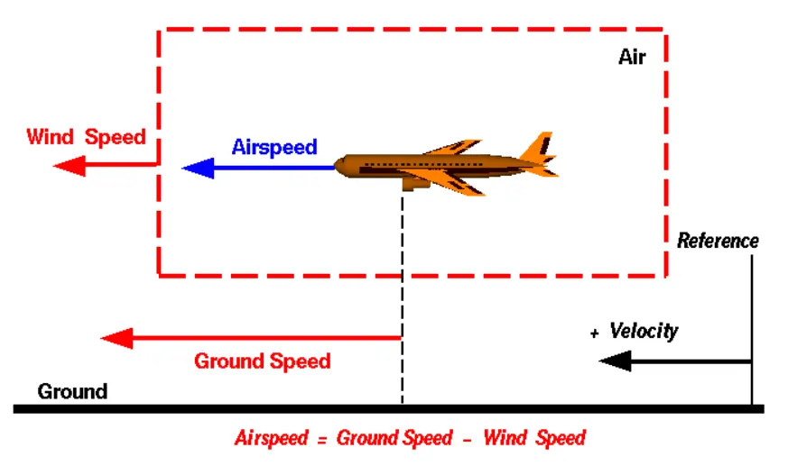
Generally, there are two different types of speed when talking about airplanes – ground speed and airspeed.
While ground speed is the airplane’s speed relative to the surface of the Earth, airspeed is the speed relative to the air it is flying in.
Ground Speed
For a reference point picked on the ground, the aircraft moves relative to the reference point at the ground speed. Ground speed is also a vector quantity so a comparison of the ground speed to the wind speed must be done according to rules for vector comparision.
It is horizontal rather than vertical speed – an aircraft climbing completely vertically would have a ground speed of zero.
Air Speed
True airspeed is simply the speed at which an aircraft is moving relative to the air it is flying in. As such, it’s also the speed at which the air is flowing around the aircraft’s wings.
In other words, while airspeed determines whether there is enough airflow around an aircraft to make it fly, ground speed determines how fast an aircraft will get to its destination.
The important quantity in the generation of lift is the relative velocity between the object and the air, which is called the airspeed. Airspeed cannot be directly measured from a ground position, but must be computed from the ground speed and the wind speed.
Wind Speed
For a reference point picked on the ground, the air moves relative to the reference point at the wind speed. Notice that the wind speed is a vector quantity and has both a magnitude and a direction. Direction is important. A 20 mph wind from the west is different from a 20 mph wind from the east. The wind has components in all three primary directions (north-south, east-west, and up-down). In this figure, we are considering only velocities along the aircraft's flight path. A positive velocity is defined to be in the direction of the aircraft's motion. We are neglecting cross wind, which occur perpendicular to the flight path but parallel to the ground, and updrafts and down drafts, which occur perpendicular to the ground.
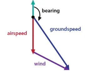
The relationship between airspeed and ground speed is fairly simple. Ground speed is simply the vector sum of airspeed and wind speed.
If the aircraft is flying in the same direction as the wind is blowing, the aircraft experiences Tail-wind, and its ground speed is higher than its airspeed. On the other hand, if the wind is blowing against the direction the aircraft is traveling in, the aircraft experiences Head-wind, and its ground speed is lower than its airspeed.
Ground Speed = Air Speed + Wind Speed
Vector calculation
3. Why is it not recommended to use aircraft engine power to move it on the ground at Airport?
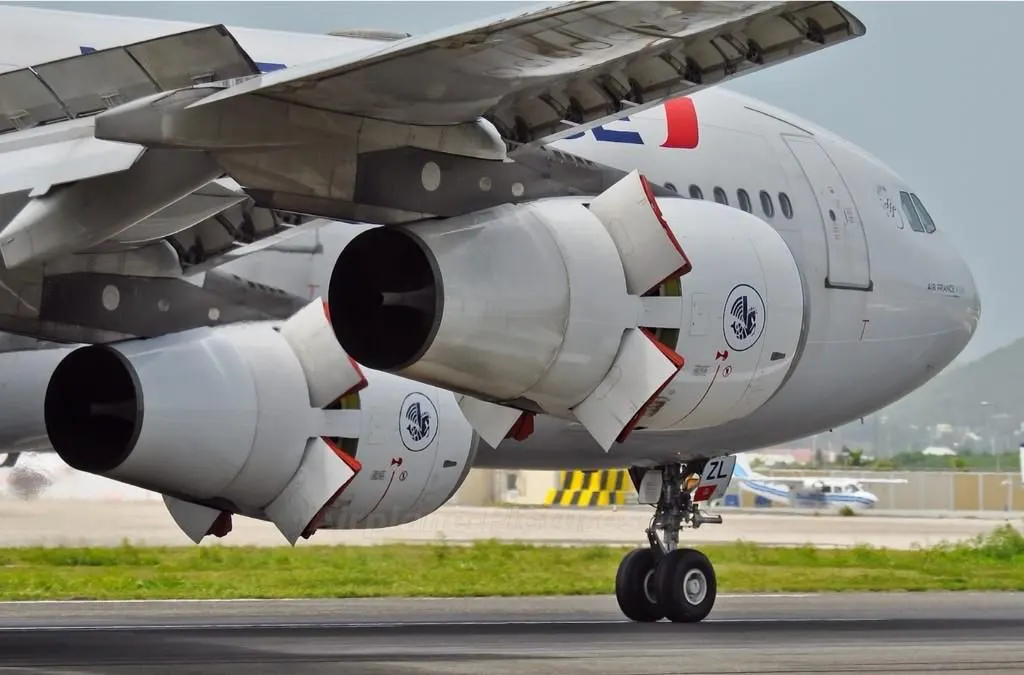
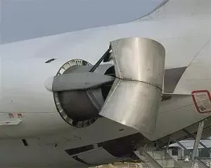
Generally the aircafts can't move in the reverse direction because the aircraft engines are not designed to move in the reverse direction.We can move reverse by backward thrust but with the high risk. Aircrafts can taxi in the Airports by smaller thrust by checking with the ground controller's taxi map.
To move in the reverse direction push-back trucks are used.
Taxiing: is the movement of an aircraft on the ground, under its own power. An airplane uses taxiways to taxi from one place on an airport to another; for example, when moving from a hanger to the runway. The term "taxiing" is not used for the takeoff roll and landing rollout.
Towing or push-back: Pushback means the movement of an aircraft from a nose-in parking stand using the power of a specialised ground vehicle attached to or supporting the nose landing gear.
An aircraft towed by a tug
Backward thrust of an Aircraft
The ‘traditional’ method of allowing the ground vehicle to move an aircraft is to attach it to the aircraft nose landing gear by means of a towbar. These must be approved for use with a particular aircraft type and clearly marked as such since there is no universal towbar specification. An alternative method which is becoming more common for towing is the use of a specialised vehicle called a ‘towbarless tug’. This positions two low level ‘arms’ either side of the aircraft nose landing gear and these are used to engage with the aircraft gear leg and raise it slightly off the ground.
Resions for not recommended to use aircraft engine power to move it on the ground at Airport are:
- It is not easy to taxi an airplanes in a busy airports because of the longer wings. When you have another aircraft packed close to you it is quite difficult to judge the distance between your ings and packed aircrafts. Having a push-back trucks moves safer distance with a enough space for you without aircraft engines.
- The backwords trust would do damage the jetsway or throw up loose debris on the thermac which would end up getting sucked up in a running jet engine of another plain. That's why we see no reverse thrusters sign at the gates.
- Using an aircraft engine power causes a lot of noise. And having huge risk of jet blast and surroundings.
- Aircraft Pilots have very limited view of their surroungings and may fail to notice the ground vehicle or even another aircraft. The tug operator can see everything clearly.
-------------------------------------------------------------------------------------------------------------------------------------------------------------------------------------------------------------------------------------------
4. How an aircraft is pushed to runway when its ready to take off?
Extensive planning is needed before an aircraft can take off. The airline will pass this on to the pilots, who will check all the information and fine-tune it. The entire infrastructure and the technical condition are checked. This check is called “Pre-flight Check.” All important technical functions are examined, so to speak, under the magnifying glass.
During the so-called “Outside Check”, one of the pilots checks the external condition of the jet during an obligatory tour. Particular attention is paid to obvious damage, the condition of the turbines and control flaps, as well as the landing gear and brakes. The other pilot feeds the on-board computer with all imaginable data. Current weather information for the start will be provided live from the respective airport.
The pilot’s “Before-Taxi-Check” (check before the start of taxiing) is also necessary. The entire procedure is mandatory and must be carried out before each flight. Among other things, it is checked whether the doors are locked, all passengers are strapped in and the instruments provide correct information.
If necessary, the aircraft will then be cleared of snow and frost by the de-icing service during the cold season. Which route is flown and whether departure restrictions exist is regulated by air traffic control units (ATC) and is stored in the navigation charts in the cockpit.

Once everything is done, the aircraft is brought out of the “nose-in position” by pushback. In this position, the aircraft stands with its nose at the gate and is pushed onto the taxiway with the aid of airport tugs, as it cannot reverse itself. Once on the taxiway, it rolls towards the runway.
Ready for take-off: the wheels start rolling
Finally, it can start; the plane take-off begins. The engines howl up and the aircraft lifts slightly at the front. In most cases, the engine power is not fully utilized. In order to relieve the high-tech engines, the power peaks are reduced by a precisely calculated value. The existing track length should be used as efficiently as possible. This not only reduces the service life of the engines, but also other wear, noise and emissions.
In order to take off, a certain speed must already be reached on the runway, as this is the only way to overcome gravity so that the aircraft can take off. Commercial airliners accelerate to a proud 250 to 345 km/h.
The elevators cause the aircraft to rotate around its transverse axis. The nose of the aircraft is lifted and the nose gear lifts off. The point until which the pilot can abort the take-off is called V1. If he would take out the throttle until then, the glider would automatically perform a kind of “emergency braking”. After exceeding V1 the aircraft has to take off.
The tires of the airplanes are filled with nitrogen and only roll with it. This means that they are not driven by themselves, as in a car. The aerodynamic lift on the wings is achieved by increasing the angle of attack. First the nose wheel lifts off, then the rear wheels. The pull you can feel at this moment is caused by the gravitational force and is already over after a few seconds.
Finally the pilot takes off and retracts the landing gear. For 15 to 20 minutes the airplane is in the climb flight (Climb), before it changes into the cruise flight (Cruising).
-------------------------------------------------------------------------------------------------------------------------------------------------------------------------------------------------------------------------------------------
5. Learn about take off power, tyre design, rolling resistance, tyre pressure, brake forces when landing.
Takeoff power:
Takeoff is the phase of flight in which an aerospace vehicle leaves the ground and becomes airborne.
For aircraft that take off horizontally, this usually involves starting with a transition from moving along the ground on a runway. For balloons, Helicopters and some specialized fixed-wing aircraft, no runway is needed.
For light aircraft, usually full power is used during takeoff. Large airliner aircraft may use a reduced power for takeoff, where less than full power is applied in order to prolong engine life, reduce maintenance costs and reduce noise emissions. In some emergency cases, the power used can then be increased to increase the aircraft's performance. Before takeoff, the engines, particularly piston engine, are routinely run up at high power to check for engine-related problems. The aircraft is permitted to accelerate to rotation speed. T
The nose is raised to a nominal `5^0-15^0` nose up pitch attitude to increase lift from the wings and effect liftoff. For most aircraft, attempting a takeoff without a pitch-up would require cruise speeds while still on the runway.
The speeds needed for takeoff are relative to the motion of the air. A headwind will reduce the ground speed needed for takeoff, as there is a greater flow of air over the wings. Typical takeoff air speeds for jetliners are in the range of 240–285 kmph. Light aircraft, such as a Cessna 150, take off at around 100 kmph. Ultralights have even lower takeoff speeds. For a given aircraft, the takeoff speed is usually dependent on the aircraft weight; the heavier the weight, the greater the speed needed. Some aircraft are specifically designed for short takoff and landing, which they achieve by becoming airborne at very low speeds.
Takeoff power `(P)= (T+Fd+Fr)*V` `kW`
where,
`T= Thrust (N)`
`Fd= Drag F`orce `(N)`
`Fr=` Rolling Resistance `(N)`
Design and Construction of Aircraft tyre:
An aircraft tire is designed to withstand extremely heavy loads for short durations.The number of tires required for aircraft increases with the weight of the aircraft, as the weight of the airplane needs to be distributed more evenly. Aircraft tire tread patterns are designed to facilitate stability in high crosswind conditions, to channel water away to prevent hydroplaning, and for braking effect.
Aircraft tires also include fusible plugs, designed to melt at a certain temperature. Tires often overheat if maximum braking is applied during an aborted takeoff or an emergency landing. The fuses provide a safer failure mode that prevents tire explosions by deflating in a controlled manner, thus minimizing damage to aircraft and objects in the surrounding environment.
Carcass plies are used to form the tire. They are sometimes called casing plies. An aircraft tyre is constructed for the purpose it serves.
- They support the weight of an aircraft while it is on the ground.
- It also provides the necessary traction for braking and stopping of an aeroplane.
- Tyre also helps to absorb the shock of landing and provide cushioning the roughness of takeoff, roll-out, and taxi operations.
Unlike an automobile or truck tyre, it does not have to carry a load for a long period of continuous operation. However, an aircraft tyre absorbs the high impact loads of landing, and also it’s operating at high speeds for a short time when required.
Let’s go through some technical aspects of the tyre.
Retreading – Retreading is methods of restoring a worn tyre by renewing the tread area or by renewing the tread area plus one or both sidewalls. Repairs are included in the tyre retreading process.
Load Rating – Load rating is the maximum permissible load at a specified inflation pressure.
Ply Rating – Ply Rating is used to identify the maximum recommended load rating and inflation pressure for a specified tyre. It is an index of tyre strength.
Speed Rating – The speed rating is the maximum takeoff speed to which the tyre has been tested.
Skid Depth – Skid depth is the distance between the tread surface and the deepest groove as measured in the mould.
Aircraft tyres must have an approved speed and load rating and have sufficient clearance when retracted through landing gear to allow for tyre growth. Tyre growth is the increase in the size of the tyre due to centrifugal forces at high speed.
Aircraft tyres may be Tube-type or Tubeless:
Tubeless tyres are more advantageous over tube-type. There is no longer the use of tube-type tyre in recent aviation. Nowadays all airliners are using tubeless tyres. Tubeless that are meant to be used without a tube has the word TUBELESS on the sidewall of the tyre.
Aircraft tyres may be Radial or Bias:
Almost all airliners are using Radial tyre. Bias is an older design, and it’s mainly used for road vehicles. Radial tyres have the word RADIAL on the sidewall. Radial tires are more expensive than bias-ply tyres. Radial tires are in demand because of their lower life cycle cost and long term value.
Today’s tyres are conductive. Aircraft tyres are manufactured with tread rubber with conducting compounds to permit earthing of static charges.
In early days when tyres were not sufficiently conductive, aircraft used to have a conductive strip hanging down from the axle of the landing gear. Upon landing, this strip would be the first part of the aircraft to touch the earth. This discharges any static electricity accumulated on the outer surfaces of the aircraft.
Purpose of Chines in aviation tyre:
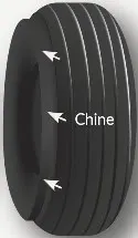
Chines are also called deflectors. Chine tyre used on the nose wheel of aircraft, specially fuselage-mounted jet engines. It diverts runway water away from the engine inlets.
Chines are circumferential protrusions that are moulded into the sidewall of nose tyres that deflect water sideways to help reduce excess water ingestion into the engines. Tyres may have chines on one or both sides, depending on the number of nose tyres on the aircraft.
Aircraft Tyre Standards:
Each tyre manufacturer produces their own designs of the tyre with different tread patterns, wear patterns, wear limits etc, and in some cases, different names for the same part of the tyre. But all tyres must meet the approved standards before being accepted by the FAA or CAA.
All commercial aircraft tyres approved under FAA Requirement Technical Standard Order (TSO) C62. A TSO is a minimum performance standard for specified materials, parts, and appliances used on civil aircraft
Rolling resistance:
Rolling resistance is the force resisting the motion when a body rolls on a surface. It is mainly caused by non-elastic effects; that is, not all the energy needed for deformation of the wheel, roadbed, etc., is recovered when the pressure is removed. Two forms of this are hysteresis losses and plastic deformation of the object or the surface. Another cause of rolling resistance lies in the slippage between the wheel and the surface, which dissipates energy.
In analogy with sliding friction, rolling resistance is often expressed as a coefficient times the normal force. This coefficient of rolling resistance is generally much smaller than the coefficient of sliding friction.
Any coasting wheeled vehicle will gradually slow down due to rolling resistance including that of the bearings, but a train, car with steel wheels running on steel rails will roll farther than a bus of the same mass with rubber tires running on tarmac. Factors that contribute to rolling resistance are the deformation of the wheels, the deformation of the roadbed surface, and movement below the surface. Additional contributing factors include wheel diameter,load on wheel, surface adhesion, sliding, and relative micro-sliding between the surfaces of contact. The losses due to hysteresis also depend strongly on the material properties of the wheel or tire and the surface.
The rolling resistance can be expressed as
`Fr = mu* W`
where
`Fr =` rolling resistance or rolling friction (N)
`mu` coefficient of rolling resistance
`W=` Weight kg
Aircraft tire pressure:
Aircraft tires generally operates at high pressures up to 200 psi (14bars) for airliners and even high for business jets. The main landing gear on the Concorde was tipically inflated to 232 psi (16 bars).while its tail bumper gear tires were as high as 294 psi (20.3 bar).The high pressure and weight load on the Concorde tyres were a significant factor.
Tests of airliner aircraft tires have shown that they are able to sustain pressures of maximum 800 psi (55 bar) before bursting. During the tests the tires have to be filled with water, to prevent the test room being blown apart by the energy that would be released by a gas when the tire bursts.
Aircraft tires are usually inflated with nitrogen to minimize expansion and contraction from extreme changes in ambient temperature and pressure experienced during flight. Dry nitrogen expands at the same rate as other dry atmospheric gases (normal air is about 80% nitrogen), but common compressed air sources may contain moisture, which increases the expansion rate with temperature.
The use of an inert gas for tire inflation eliminates the possibility of tire explosion.
Brake forces when landing:
Aircraft brakes stop a moving aircraft by converting its kinetic energy to heat energy by means of friction between rotating and stationary discs located in brake assemblies in the wheels.
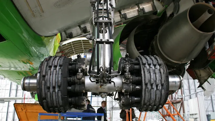
A brake assembly on a Boeing 737NG main landing gear, visible after removal of one the wheels.
Brakes provide this critical stopping function during landings to enable airplanes to stop within the length of the runway. They also stop aircraft during rejected takeoff events, in which an attempted takeoff is canceled as the airplane is rolling down the runway before it lifts off from the ground due to engine failure, tire blowout, other system failure or direction from air traffic control.
Aircraft brakes also prevent motion of the aircraft when it is parked, limit its speed during taxiing and can even help steer the aircraft on the ground by applying different levels of braking force to the left- and right-side brakes.
Aircraft brakes work in conjunction with other brake mechanisms such as thrust reversers, air brakes and spoilers. Thrust reversers are surfaces that are deployed into the path of the jet blast from the engines to redirect propulsive thrust in a direction that opposes the motion of the aircraft. Air brakes and spoilers are flight control surfaces that create additional aerodynamic drag when deployed into the path of air flowing around the aircraft.
The brake force while landing is done by three difference process they are,
Aircraft disc brakes:
Aircrafts has dis rotors in the landing gear, used to brake the wheels while touching the ground. These brakes are operated hydraulically or pneumatically.
Trust reversers:
Thrust reversers allow thrust from the engines to be used to slow down the arcraft. This is very effective in bringing down thw speed of the airceaft. By using a negative angle plane, we are turning the wind that is coming into the propeller to flow in the opposite direction.
Air Brakes:
Air Brake dedicated flight control surface that work by increasing the drag force, air brakes are designed to increase drag while making little change to lift, resulting in a higher stall speed.
these are the methods used to bring down the aircraft's speed while landing the flight.
-------------------------------------------------------------------------------------------------------------------------------------------------------------------------------------------------------------------------------------------
6.With necessary assumptions, calculate the force and power required to push / pull an aircraft by a towing vehicle.
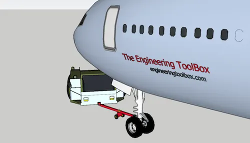
If the mass of a plane is 40,000 kg and the rolling resistance between the aircraft wheel and the tarmac is 0.02 N.
Speed of the towing truck is 8 kmph and the time required for parking is 15 Min.
Mass of a plain (m)= 40,000 kg
Rolling resistance (F_r)= 0.02 N
Speed of the truck(V) = 8 kmph = 2.2 m/s
time require for parking (t) = 15 min = 900 Sec
The Traction force required to pull an aircraft can be calculated as
Traction Force `(F_T)= F_d+F_r`
Since the truck moves in a low speed, the aerodynamic force is negligible.
`thereforeF_d=0`
`F_r = mu*m*g`
`F_r=`0.02 (40000 kg) (9.81 m/s2)
`F_r= 7848 N`
`therefore``F_T = 7848 N`
This force can be delivered by a pulling truck or - as occasionally seen - by a number of pulling people. Enough weight for the pullers are required to create friction forces against the tarmac that equals the plane rolling resistance.
Power Required to pull/push an aircraft:
`P= F_T*V`
= 7848*2.2
= 17.265 kW
---------------------------------------------------------------------------------------------------------------------------------------------------------------------------------------------------------------------------------------
7. Design an electric powertrain with type of motor, it’s power rating, and energy requirement to fulfill aircraft towing application. Estimate the duty cycle range to control the aircraft speed from zero to highest. Make all required assumptions. Prepare a table of assumed parameters. Draw a block diagram of powertrain.
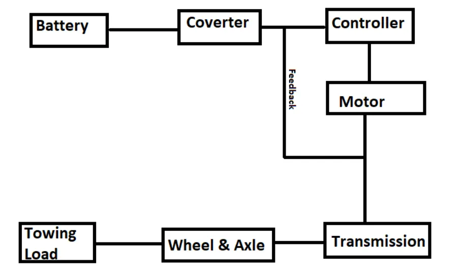
Design of an electric powertrain for an Aircraft towing tractor:
- Energy required to be delivered
- Motor selection based on power requirements
- Power converters to upscale the armature voltage as required
- Switching Techniques with Duty cycle ratio for speed control of the Motor
Assumed parameters:
| S.No | Assumed parameters | Values |
| 1 | Weght of an aircraft | 40,000 kg |
| 2 | Weight of towing tractor | 5000 kg |
| 3 | Rolling resistance coefficient of aircraft | 0.04 |
| 4 | Rolling resistance coefficient of towing truck | 0.02 |
| 5 | Velocity of an aircraft while towing | 8 kmph |
| 6 | Density of air | 1.225 kg/m^3 |
| 7 | Frontal Area of an aircraft | 20 m^2 |
| 8 | Drag coefficient of an aircraft | 0.026 |
| 9 | Towing tractor gear ratio (G) | 11 |
| 10 | Towing tractor tire radius ( R) | 0.635 m |
| 11 | Operational time of towing for one cycle | 0.33 hr |
| 12 | Battery Voltage | 350 V |
| 13 | Battery Current | 350 A |
| 14 | Motor terminal voltage | 700 V |
| 15 | Power converter used | Bi-directional DC-Dc booster |
| 16 | Max. Duty Cycle | 70% |
The Traction force required to pull an aircraft can be calculated as
Traction Force `(F_T)= F_d+F_r`
Since the truck moves in a low speed, the aerodynamic force is negligible.
`thereforeF_d=0`
`F_r = mu*m*g`
`F_r=`0.02 (40,000 kg) (9.81 m/s2)
`F_r= 7848 N`
`therefore``F_T = 7848 N`
Power Required to pull/push an aircraft:
`P= F_T*V`
P = 7848*2.2
P= 17.265 kW
Energy required to fulfill aircraft towing:
Energy (E)= Power * Time
`E= P*t`
`= 17.265 kW* 0.33 hr`
`= 5.697 kWh`
The torque required to pull/push of aircraft:
`T=F_T*r/G`
where,
F_T= Traction force (N)
r= Radius of tire (m)
G= Gear ratio
`T= 7848*0.635/11`
`T= 453 Nm`
Now for pulling or pushing an aircraft our electric towing tractor requires the following power, energy and torque,
Power (P)= 17.265 kW
Energy (E)= 5.697 kW-h
Torque (T)= 453 Nm
Therefore the battery must be able to store the energy of 5.697 kW-h and should deliver the energy throughout the run time in order for the motor to produce the 453 Nm of torque instantaneously. Thus the storage of energy in batteries with high performance ultracapacitors are selected to fulfill the required power delivery.
Motor Selection:
Here we have selected a Brushless DC Motor type that has a power rating of 17.265 kW and with the gear ratio and the tranmission it should be able to produce the 453 Nm of torque instantaneously.
The Battery voltage (V) = 350 V
The Battery Current (A) = 350 A
For getting maximum power output from the motor(17.265 kW), the voltage applied to the motor terminals must be 700 V (Assume).
Power Converters:
Here we use a DC-DC power converter to upscale the voltage level from the battery to the required level so that when supplied to the motor we can get the desired power uotput from the motor. The bi-directional DC-DC converters find applications in places where battery charging, regenerative braking, and backup power are required. The power flow in a bidirectional converter is usually from a low voltage end such as battery or a supercapacitor to a high voltage side ans id referred to as boost operation. During regenerative braking, the power flows back to the low voltage bus to recharge the battery. As a backup power system, the bidirectional DC-DC converter facilitates the safe operation of the vehicle when ICEs or electric drives fail to drive the motor. The boost converter converts the 350V of armature voltage to a high voltage level of 1000V.
Speed control of the vehicle:
The vehicle uses power from the battery source to drive the motor and then further to drive the wheels in order to move the vehicle. The speed and torque generated from the motor is very important to drive the vehicle as per the Driver's desire. If we connect the battery directly to the motor will spin with a speed and torque characteristics which will be based on the full power of the battery voltage. We does not required the full power in all the driving conditions so we need to adopt a power controller between the battery and the motor so that the motor speed may be controlled by the driver to drive the vehicle as desired. For controlling the vehicle power we use the soft switching operation technique here. The amount of power can be controlled by changing the duty cycle value. Considering the loeesee we take 70% of duty cyclr to deliver the maximum power of the motor
Motor terminal voltage = Armature voltage * Duty cycle
= 1000*0.7
= 700 V
with the 70% Duty cycle the voltage at motor terminal = 700 V, which gives the full power with all the gearings, instantaneously. Thus by varying the Duty cycle value the speed of the vehicle is controlled.
Hence, the Heavy duty towing tractor for an Aircraft is designed for operating an exterem local conditions.
Block diagram of powertrain:
Reference: