Week 7 - Simulation of a 1D Super-sonic nozzle flow simulation using Macormack Method
Simulation of a 1D Super-sonic nozzle flow simulation using Macormack Method
Aim:
To simulate the isentropic flow through a quasi 1D subsonic-supersonic nozzle for both conservation and non-conservation forms of the governing equations and sovle them using the MacCormack's technique.
1D Super-sonic nozzle flow:
Here we are going to simulate the isentropic flow through a quasi 1D subsonic-supersonic nozzle for both conservation and non-conservation forms of the governing equations using the MacCormack's technique.
Computational Fluid Mechanics by Anderson is used for the reference.
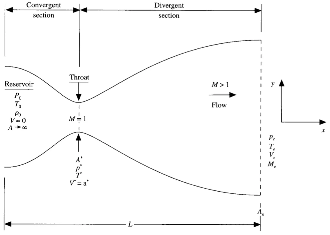
The above sketch shows a typical C-D Nozzle through which a supersonic flow can occur. We consider the steady, isentropic flow through a convergent-divergent nozzle. The flow at the inlet to the nozzle comes from a reservoir where the pressure and temperature are denoted by `P_o` and `T_o` respectively. The cross-sectional area of the reservoir is larger (`A rightarrow prop`), and hence the velocity is very small (`V rightarrow 0`). Thus, `P_o` and `T_o` are the stagnation values, or total pressure and tota temperature, respectively. The flow expands isentropically to supersoic speeds at the nozzle exit, where the exit pressure, temperature, velocity and Mach number are denoted by `P_e, T_e, V_e and M_e,` respectively. The flow is locally subsonic in the convergent section of the nozzle, sonic at the throat and supersonic at the divergent section. The sonic flow (M=1) at the throat means that the local velocity at this local is equal to the speed of sound. Using an asterisk to denote sonic flow values, we have at the throat `V=V^*=a^*`. Similarly, the sonic flow values of pressure and temperature are denoted by `P^* and T^*`, respectively. The area of the sonic throat is denoted by `A^*`. We assume that at a given section. Hence, although the area is A, the flow properties are uniform accross that section. Hence, although the area of the nozzle changes as a function of distance along the nozzle,x and therefore in reality the flow field is two-dimensional, e make the assumption that the flow properties vary only with x; this is tantamount to assuming uniform flow properties accross any given cross section. Such flow is defined as quasi-one-dimensional flow.
The governing continunty, momentum and energy equations for this quasi-one-dimensional, steady, isentropic flow can be expressed, as respectively, as
Continuty equation: `rho_1 V_1 A_1 = rho_2 V_2 A_2`
Momentum equation: `P_1 A_1+rho_1V_1^2A_1+int_(A_1)^(A_2) PdA = P2A2+rho_2V_2^2A_2`
Energy equation: `h_1+V_1^2/2=h_2+V_2^2/2`
Generally, Governing equations are two types conservative and non-conservative form. Here we are solving both the forms.
Conservative form:
Continuity equation: `(del(rhoA))/(delt) +(del(rhoAV))/(delx) =0`
Momentum equation: `(del(rhoAV))/(delt)+(del[rhoAV^2+(1/gamma)*PA])/(delx) = 1/gammaP(delA)/(delx)`
Energy equation: `(del[rho(e/(gamma-1)+gamma/2V^2)*A])/(delt)+(del[rho(e/(gamma-1)+gamma/2V^2)*AV+PAV])/(delx)=0`
Non-Conservative form:
Continuity equation: `(delrho)/(delt)=-rho(delV)/(delx)-rhoV(del(lnA))/(delx)-V(delrho)/(delx)`
Momentum equation: `(delV)/(delt)=-V(delV)/(delx)-1/gamma((delT)/(delx)+T/rho(delrho)/(delx))`
Energy equation: `(delT)/(delt) = -V(delT)/(delx)-(gamma-1)T((delV)/(delx)+V(del(lnA))/(delx))`
MacCormack method:
MacCormack method is a widely used discretixation scheme for the numerical solution of hyperbolic partial differential equations. The MacCormack method ia s variation of the two -steps Lax-Wendroff scheme but is much simpler in the application. It is second-order sccurate in both space and time. For second-order accuracy in time a predictor-corrector strategy is employed and their average is used to calculate the actual derivatives. In the predictor step the G-E is replaced spatial derivatives by forward differences and in the corrector step with rearward differences.
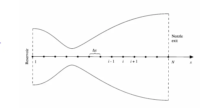
Non-conservation from:
Predictor step:
forward differencing,
`((delrho)/(delt))_i^t=-rho_i^t(V_(i+1)^t-V_i^t)/(Deltax)-rho_i^t*V_i^t(ln A_(i+1)-ln A_i)/(Deltax)-V_1^t(rho_(i+1)^t-rho_i^t)/(Deltax)`
`((delV)/(delt))_i^t = -V_i^t ((V_(i+1)^t -V_i^t ))/(Deltax)-(1/gamma)(((T_(i+1)^t-T_i^t))/(Deltax)+(T_i^t)/(rho_i^t)(rho_(i+1)^t-rho_i^t)/(Deltax))`
`((delT)/(delt))_i^t = -V_i^t ((T_(i+1)^t -T_i^t ))/(Deltax)-(gamma-1)T_i^t(((V_(i+1)^t-V_i^t))/(Deltax)+(V_i^t)(ln A_(i+1)^t-ln A_(i))/(Deltax))`
We obtain the predicted values of `rho`, `T``V` from
`rho_i^(t+Deltat)=rho_i^t+((delrho)/(delt))_i^tDeltat`
`V_i^(t+Deltat)=V_i^t+((delV)/(delt))_i^tDeltat`
`T_i^(t+Deltat)=T_i^t+((delT)/(delt))_i^tDeltat`
corrector step:
rearward differencing,
`(bar(delrho)/(delt))_i^(t+Deltat) = -barrho_i^(t+Deltat)((barV_(i)^(t+Deltat)-barV_(i-1)^(t+Deltat)))/(Deltax)-barrho_i^(t+Delta).barV_(i)^(t+Deltat)((ln A_i-ln A_i-1))/(Deltax)-barV_(i)^(t+Deltat)((barrho_i^(t+Deltat)-barrho_(i-1)^(t+Deltat)))/(Deltax)`
`(bar(delV)/(delt))_i^(t+Deltat) = -barV_i^(t+Deltat)*(barV_i^(t+Deltat)-barV_(i-1)^(t+Deltat))/(Deltax)-1/gamma(((barT_i^(t+Deltat)-barT_(i-1)^(t+Deltat)))/(Deltax)+((barT_i^(t+Deltat))/barrho_i^(t+Deltat))*((barrho_i^(t+Deltat)-barrho_(i-1)^(t+Deltat)))/(Deltax))`
`(bar(delT)/(delt))_i^(t+Deltat) = -barV_i^(t+Deltat)((barT_i^(t+Deltat)-barT_(i-1)^(t+Deltat)))/(Deltax)-(gamma-1)*barT_i^(t+Deltat)*((barV_i^(t+Deltat)-(barV_(i-1)^(t+Deltat)))/(Deltax)+barV_i^(t+Deltat)*((ln A_i-ln A_(i-1)))/(Deltax))`
Average time derivatives are taken by,
`((delrho)/(delt))_(avg) = 0.5[((delrho)/(delt))_i^t+((delrho)/(delt))_i^(t+Deltat)]`
`((delV)/(delt))_(avg) = 0.5[((delV)/(delt))_i^t+((delV)/(delt))_i^(t+Deltat)]`
`((delT)/(delt))_(avg) = 0.5[((delT)/(delt))_i^t+((delT)/(delt))_i^(t+Deltat)]`
Finally we have for the corrected values we have flow-field variables at time `t+Deltat`
`rho_i^(t+Deltat)=rho_i^t+((delrho)/(delt))_(avg)Deltat`
`V_i^(t+Deltat)=V_i^t+((delV)/(delt))_(avg)Deltat`
`T_i^(t+Deltat)=T_i^t+((delT)/(delt))_(avg)Deltat`
From Anderson text book, the shape of the nozzle is given by
Area `A = 1+2.22*(x-1.5)^2` `0<=x<=3`
Boundry conditions:
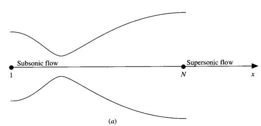
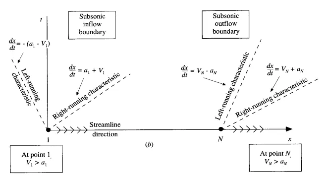
Initial conditions are specified as
`rho = 1-0.3146x`
`T = 1-0.2314x`
`V = (0.1+1.09x)*T^(1/2)`
Boundry conditions at subsonic Inflow
`V(1)=2*V(2)-V(3)`
Boundry conditions at supersonic Outflow
`rho(n)=2*rho(n-1)-rho(n-2)`
`V(n) = 2*V(n-1)-V(n-2)`
`T(n) = 2*T(n-1)-T(n-2)`
Conservation from:
Let us define the elements of solution vector (U), the flux vector (F) and the source term (J) as follows,
`U_1=rho'A'`
`U_2=rho'A'V'`
`U_3 = rho'((e')/(gamma-1)+gamma/2V'^2)A'`
`F_1 = rho'A'V'`
`F_2=rho'A'V'^2+1/gammaP'A'`
`F_3 = U_3V'+P'A'V'`
`J_2 = 1/gammaP'(delA')/(delx')`
With these elements thw governing equations can be written as
`(delU_1)/(delt') = (delF_1)/(delx')`
`(delU_2)/(delt')=-(delF_2)/(delx')+J_2`
`(delU_3)/(delt')= -(delF_3)/(delx')`
To obtain the premitive variables we must decode the elements U1,U2,U3 as follows
`rho' = U_1/(A')`
`V'=U_2/U_1`
`T' = e' = (gamma-1)(U_3/U_1-gamma/2V'^2)`
`P=rho'T'`
Pure form of the Flux terms,
`F_1 = U_2`
`F_2 = U_2^2/(U_1)+(gamma-1)/gamma(U_3-gamma/2U_2^2/U_1)`
`F_3 = gamma(U_2U_3)/U_1-gamma((gamma-1))/2U_2^3/U_1^2`
`J_2=(gamma-1)/gamma(U_3-gamma/2U_2^2/U_1^2)(del(ln A))/(delx)`
As similar to non-conservative from the predictor step the G-E is replaced spatial derivatives by forward differences and in the corrector step with rearward differences.
Then take the average of them and update the final solution.
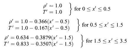
Initial conditions:
Since the dependent variables being solved U1,U2,U3, we need initial conditions for these same variables at time t=0 in order to start the finite-difference solution. The initial conditions for U1,U2,U3 are allow initial conditions for F1,F2,F3 to be obtained. such initial conditions for F1,F2 and F3 are needed to form the `x`derivatives on the right hand side.
The initial conditions are
Boundary conditions:
The boundary conditions for the subsonic-supersonic isentropic flow solution using the conservation form of the governing equations are theoritically same.
The flow properties at the downstream, supersonic outflow boundry are obtained by linear extrapolation form the two adjacent internal points. If `n` is donetes the grid point at the outflow boundary, then
`(U_1)_n = 2(U_1)_(n-1) - (U_1)_(n-2)`
`(U_2)_n = 2(U_2)_(n-2) - (U_2)_(n-2)`
`(U_3)_n = 2(U_3)_(n-3) - (U_3)_(n-2)`
MATLAB Main code:
%  Supersonic nozzle flow equation
clear all
close all
clc

% Defining Inputs
L = 3;                     % length of the nozzle
n = 31;                    % No.of grid points
x = linspace(0,L,n);       % Defining Mesh
dx = x(2)-x(1);            % Mesh Size
throat = (n+1)/2;          % Throat
nt = 1400;                 % No.of iterations % Time steps
a = 1+2.2.*(x-1.5).^2;     % Area
% Fluid properties
gamma = 1.4;
C = 0.5;                    % CFL number

% Non-conservative form
 [rho_Nc,v_Nc,T_Nc,P_Nc,M_Nc,Mass_flow_Nc] = NC_fcn(n,x,dx,gamma,throat,nt,a,C);
% Conservative form
 [rho_C,v_C,T_C,P_C,M_C,Mass_flow_C] = con_fcn(n,x,dx,gamma,throat,nt,a,C);

% Comparison of steady state results, Conservative & Non-conservative results
Terms = [{'ND density'};{'ND tempearture'};{'ND pressure'};{'Mach number'};{'ND velocity'}];
Exact_Sol = [0.634;0.833;0.528;1;1];
Non_conservative_Sol = [rho_Nc(throat);T_Nc(throat);P_Nc(throat);M_Nc(throat);v_Nc(throat)];
Conservative_Sol = [rho_C(throat);T_C(throat);P_C(throat);M_C(throat);v_C(throat)];
table(Terms,Exact_Sol,Non_conservative_Sol,Conservative_Sol)

% Comparison of Normalized mass flow rate distributions of Non_conservative form & Conservative form
figure(7)
plot(x,Mass_flow_Nc)
hold on
plot(x,Mass_flow_C)
xlabel('length of nozzle')
ylabel('mass flow rate')
legend('Non-conservative form','Conservative from')
title('Comparison mass flow distributions of Non-conservative form & Conservative from')
grid on
Non-conservative form Function code:
function [rho_Nc,v_Nc,T_Nc,P_Nc,M_Nc,Mass_flow_Nc] = NC_fcn(n,x,dx,gamma,throat,nt,a,C)

% Calculate initial profiles
rho_Nc = 1-0.31468*x;                     % Density
T_Nc = 1-0.2314*x;                        % Temperature
v_Nc = (0.1+1.09*x.*T_Nc.^0.5);           % Velocity

% Non-conservative form of Supersonic nozzle flow equation
% Maccormack method
    % Outer loop
    tic
for k=1:nt
    % Predictor step
%     % Creating copy
    rho_old = rho_Nc;
    v_old = v_Nc;
    T_old = T_Nc;
    dt = min(C.*dx./(sqrt(T_Nc)+v_Nc));
    for j=2:n-1
         % derivatives
        dv_dx = (v_Nc(j+1)-v_Nc(j))/dx;
        drho_dx = (rho_Nc(j+1)-rho_Nc(j))/dx;
        dT_dx = (T_Nc(j+1)-T_Nc(j))/dx;
        dloga_dx = (log(a(j+1))-log(a(j)))/dx;

        % Continuty Equation
        drho_dt_p(j) = -rho_Nc(j)*dv_dx-rho_Nc(j)*v_Nc(j)*dloga_dx-v_Nc(j)*drho_dx;

        % Momentum Equation
        dv_dt_p(j) = -v_Nc(j)*dv_dx-(1/gamma)*(dT_dx+(T_Nc(j)/rho_Nc(j))*drho_dx);

        % Energy Equation
        dT_dt_p(j) = -v_Nc(j)*dT_dx-(gamma-1)*T_Nc(j)*(dv_dx+v_Nc(j)*dloga_dx);

        % Solution update
        v_Nc(j) = v_Nc(j)+dv_dt_p(j)*dt;
        rho_Nc(j) = rho_Nc(j)+drho_dt_p(j)*dt;
        T_Nc(j) = T_Nc(j)+dT_dt_p(j)*dt;

    end

        % Corrector step

        for j=2:n-1
        % derivatives
        dv_dx = (v_Nc(j)-v_Nc(j-1))/dx;
        drho_dx = (rho_Nc(j)-rho_Nc(j-1))/dx;
        dT_dx = (T_Nc(j)-T_Nc(j-1))/dx;
        dloga_dx = (log(a(j))-log(a(j-1)))/dx;

        % Continuty Equation
        drho_dt_c(j) = -rho_Nc(j)*dv_dx-rho_Nc(j)*v_Nc(j)*dloga_dx-v_Nc(j)*drho_dx;

        % Momentum Equation
        dv_dt_c(j) = -v_Nc(j)*dv_dx-(1/gamma)*(dT_dx+(T_Nc(j)/rho_Nc(j))*drho_dx);

        % Energy Equation
        dT_dt_c(j) = -v_Nc(j)*dT_dx-(gamma-1)*T_Nc(j)*(dv_dx+v_Nc(j)*dloga_dx);

        end
        % Compute the average time derivative
        drho_dt = 0.5*(drho_dt_p+drho_dt_c);
        dv_dt = 0.5*(dv_dt_p+dv_dt_c);
        dT_dt = 0.5*(dT_dt_p+dT_dt_c);

        % Final solution update
        for i = 2:n-1
            rho_Nc(i) = rho_old(i)+drho_dt(i)*dt;
            v_Nc(i) = v_old(i)+dv_dt(i)*dt;
            T_Nc(i) = T_old(i)+dT_dt(i)*dt;
        end

        % Applying Boundry conditions
        % Inlet Boundry conditions
        v_Nc(1) = 2*v_Nc(2)-v_Nc(3); % Velocity
        % Outlet Boundry conditions
        v_Nc(n) = 2*v_Nc(n-1)-v_Nc(n-2);
        rho_Nc(n) = 2*rho_Nc(n-1)-rho_Nc(n-2);
        T_Nc(n) = 2*T_Nc(n-1)-T_Nc(n-2);

        % Calculating Pressure, Mach number & mass flow rate
        P_Nc = rho_Nc.*T_Nc;                % Pressure
        M_Nc = v_Nc./(T_Nc.^(0.5));         % Mach number
        Mass_flow_Nc = rho_Nc.*v_Nc.*a;     % Mass flow rate

        % Capturing flow field values at throat for each time step
        rho_throat(k) = rho_Nc(throat);
        v_throat(k) = v_Nc(throat);
        T_throat(k) = T_Nc(throat);
        P_throat(k) = P_Nc(throat);
        M_throat(k) = M_Nc(throat);
        flow_rate_throat(k) = Mass_flow_Nc(throat);

        figure(1)
        % Variation of Mass flow rate distribution inside the nozzle at different time steps during the time-marching process
        if k==100
            plot(x,Mass_flow_Nc)
            hold on
        else if k==200
                plot(x,Mass_flow_Nc)
                hold on
            elseif k==500
                plot(x,Mass_flow_Nc)
                hold on
            else if k==1000
                    plot(x,Mass_flow_Nc)
                    hold on
                else if k==1200
                        plot(x,Mass_flow_Nc)
                        hold on
                        legend('100 Delta','200 Delta','500 Delta','1000 Delta','1200 Delta','Analytical solution','Initial flow rate')
                        title('Mass flow rate distribution at different time steps in Non-conservation form')
                        xlabel('Non dimensional length of nozzle')
                        ylabel('Mass flow rate in Non-conservative form')
                        grid on
                    end
                end
            end
        end

end
Time_Nc=toc
        figure(2)
        % Timewise variation of the flow field variables and mach number at the nozzle throat
        % Time-wise variation of the primitive variables
        plot(M_throat)
        hold on
        plot(rho_throat)
        hold on
        plot(v_throat)
        hold on
        plot(T_throat)
        hold on
        plot(P_throat)
        legend('Mach number','(rho/rho_o)','(v/a_o)','(T/T_o)','(P/P_o)')
        xlabel('No.of time steps')
        ylabel('M,rho/rho_o,v/v_o,T/T_o,p/P_o')
        title('Timewise variation of non dimensional flow field variables at throat in Non-conservative form')
        grid on
        figure(3)
        %  Steady-state distribution of primitive variables inside the nozzle
        subplot(5,1,1)
        plot(x,M_Nc)
        xlabel('Non dimensional length')
        ylabel('M')
        legend('Mach number')
        subplot(5,1,2)
        plot(x,v_Nc)
        xlabel('Non dimensional length')
        ylabel('v/a_o')
        legend('Non dimensional velocity')
        subplot(5,1,3)
        plot(x,rho_Nc)
        xlabel('Non dimensional length')
        ylabel('rho/rho_o')
        legend('Non dimensional density')
        subplot(5,1,4)
        plot(x,T_Nc)
        xlabel('Non dimensional length')
        ylabel('T/T_o')
        legend('Non dimensional Temperature')
        subplot(5,1,5)
        plot(x,P_Nc)
        xlabel('Non dimensional length')
        ylabel('P/P_o')
        legend('Non dimensional Pressure')
        grid on
        title(' Steady-state distribution of primitive variables inside the nozzle in Non-conservative form')
%
end
Conservative form Function code:
function [rho_C,v_C,T_C,P_C,M_C,Mass_flow_C] = con_fcn(n,x,dx,gamma,throat,nt,a,C)
  tic
% Calculate initial profiles
for i=1:n
    if x(i)<0.5
        rho_C(i)=1;
        T_C(i)=1;
    elseif x(i)>=0.5 && x(i)<1.5
        rho_C(i)=1-0.366*(x(i)-0.5);
        T_C(i)=1-0.167*(x(i)-0.5);
    elseif x(i)>=1.5 && x(i)<=3.5
        rho_C(i)=0.634-0.3879*(x(i)-1.5);
        T_C(i)=0.833-0.3507*(x(i)-1.5);
    end
    v_C(i)=0.59/(rho_C(i)*a(i));

end
%dt = min(C.*dx./(sqrt(T_C)+v_C));
dt = 0.0267; %Textbook value in Anderson to verify results
% Conservative form of Supersonic nozzle flow equation
    % Maccormack method
    % Outer loop
U1 = rho_C.*a;
U2 = rho_C.*a.*v_C;
U3 = U1.*(T_C/(gamma-1))+((gamma/2).*v_C.^2);
    tic
for k=1:nt
    % Predictor step
%     % Creating copy
    U1_old=U1;
    U2_old=U2;
    U3_old=U3;

    F1=U2;
    F2=U2.^2./U1+((gamma-1)/gamma).*(U3-(gamma/2)*U2.^2./U1);
    F3=gamma.*U2.*U3./U1-0.5*gamma*(gamma-1).*U2.^3./U1.^2;

    for i=2:n-1

        J2=(1/gamma)*rho_C(i)*T_C(i)*((a(i+1)-a(i))/dx);

        dU1dtp(i)=-(F1(i+1)-F1(i))/dx;
        dU2dtp(i)=-(F2(i+1)-F2(i))/dx+J2;
        dU3dtp(i)=-(F3(i+1)-F3(i))/dx;

        %predicted values
        U1(i)=U1_old(i)+dU1dtp(i)*dt;
        U2(i)=U2_old(i)+dU2dtp(i)*dt;
        U3(i)=U3_old(i)+dU3dtp(i)*dt;

    end
    % Update of flux variables for corrector step
    F1=U2;
    F2=U2.^2./U1+((gamma-1)/gamma).*(U3-(gamma/2)*U2.^2./U1);
    F3=gamma.*U2.*U3./U1-0.5*gamma*(gamma-1).*U2.^3./U1.^2;
    rho_C=U1./a;
    T_C=(gamma-1).*(U3./U1-(gamma/2).*(U2./U1).^2);

        % Corrector step

        for i=2:n-1
        J2=(1/gamma)*rho_C(i)*T_C(i)*((a(i)-a(i-1))/dx);

        dU1dtc(i)=-(F1(i)-F1(i-1))/dx;
        dU2dtc(i)=-(F2(i)-F2(i-1))/dx+J2;
        dU3dtc(i)=-(F3(i)-F3(i-1))/dx;

        end
        % Compute the average time derivative
        dU1_dt = 0.5*(dU1dtp+dU1dtc);
        dU2_dt = 0.5*(dU2dtp+dU2dtc);
        dU3_dt = 0.5*(dU3dtp+dU3dtc);

        % Final solution update
        for j = 2:n-1
             U1(j) = U1_old(j)+(dU1_dt(j))*dt;
             U2(j) = U2_old(j)+(dU2_dt(j))*dt;
             U3(j) = U3_old(j)+(dU3_dt(j))*dt;
        end

        % Applying Boundry conditions
    %inlet
    U1(1)=a(1);
    U2(1)=2*U2(2)-U2(3);
    v_C(1)=U2(1)/U1(1);
    U3(1)=U1(1)*(T_C(1)/(gamma-1)+(gamma/2)*v_C(1)^2);

    %Outlet
    U1(n)=2*U1(n-1)-U1(n-2);
    U2(n)=2*U2(n-1)-U2(n-2);
    U3(n)=2*U3(n-1)-U3(n-2);


         rho_C=U1./a;
         v_C=U2./U1;
         T_C=(gamma-1).*(U3./U1-(gamma/2).*v_C.^2);
         P_C = rho_C.*T_C;
         M_C = v_C./sqrt(T_C);
         Mass_flow_C =  rho_C.*a.*v_C;

       % Capturing flow field values at throat for each time step
        rho_throat(k) = rho_C(throat);
        v_throat(k) = v_C(throat);
        T_throat(k) = T_C(throat);
        P_throat(k) = P_C(throat);
        M_throat(k) = M_C(throat);
        flow_rate_throat(k) = Mass_flow_C(throat);

        figure(4)
          % Variation of Mass flow rate distribution inside the nozzle at different time steps during the time-marching process
        if k==100
            plot(x,Mass_flow_C)
            hold on
        else if k==200
                plot(x,Mass_flow_C)
                hold on
            elseif k==500
                plot(x,Mass_flow_C)
                hold on
            else if k==1000
                    plot(x,Mass_flow_C)
                    hold on
                else if k==1200
                        plot(x,Mass_flow_C)
                        hold on
                        legend('100 Delta','200 Delta','500 Delta','1000 Delta','1200 Delta','Analytical solution','Initial flow rate')
                        title('Non dimensional mass flow rate distribution accross the nozzle at different time steps - conservation form')
                        xlabel('Non dimensional distance x/L')
                        ylabel('Mass flow rate in conservative form')
                        grid on
                    end
                end
            end
        end


end
Time_C =toc
        figure(5)
        % Steady-state distribution of primitive variables inside the nozzle
        subplot(5,1,1)
        plot(x,M_C)
        xlabel('Non dimensional length')
        ylabel('M')
        legend('Mach number')
        subplot(5,1,2)
        plot(x,v_C)
        xlabel('Non dimensional length')
        ylabel('v/v_o')
        legend('Non dimensional velocity')
        subplot(5,1,3)
        plot(x,rho_C)
        xlabel('Non dimensional length')
        ylabel('rho/rho_o')
        legend('Non dimensional density')
        subplot(5,1,4)
        plot(x,T_C)
        xlabel('Non dimensional length')
        ylabel('T/T_o')
        legend('Non dimensional Temperature')
        subplot(5,1,5)
        plot(x,rho_C)
        xlabel('Non dimensional length')
        ylabel('P/P_o')
        legend('Non dimensional Pressure')
        title('Steady state values of flow field variables in Conservative form')
        grid on

        figure(6)
        % Timewise variation of the flow field variables and mach number at the nozzle throat
        plot(M_throat)
        hold on
        plot(rho_throat)
        hold on
        plot(v_throat)
        hold on
        plot(T_throat)
        hold on
        plot(P_throat)
        legend('Mach number','non dimensional density(rho/rho_o)','non dimensional Velocity (v/a_o)','non dimensional Temperature(T/T_o)','non dimensional Pressure(P/P_o)')
        xlabel('No.of time steps')
        ylabel('M,rho/rho_o,v/a_o,T/T_o,P/P_o')
        title('Timewise variation of non dimensional flow field variables at throat in Conservative form')
        grid on

end
Program is written by using Macormack Method for solving both Non-conservative and conservative form.
Results:
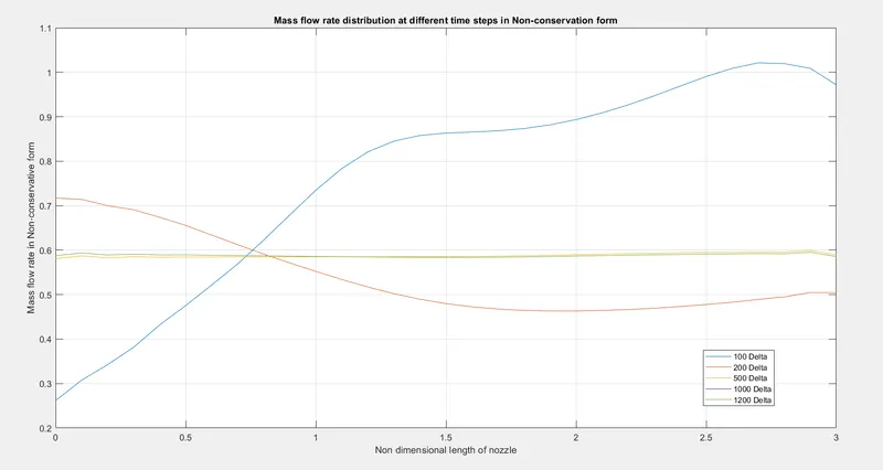
- Variation of Mass flow rate distribution inside the nozzle at different time steps during the time-marching process in Non-Conservative form:
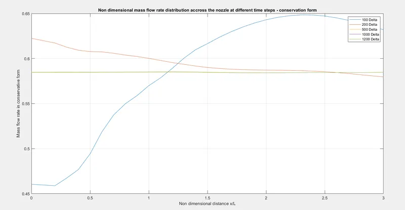
- Variation of Mass flow rate distribution inside the nozzle at different time steps during the time-marching process in Conservative form:
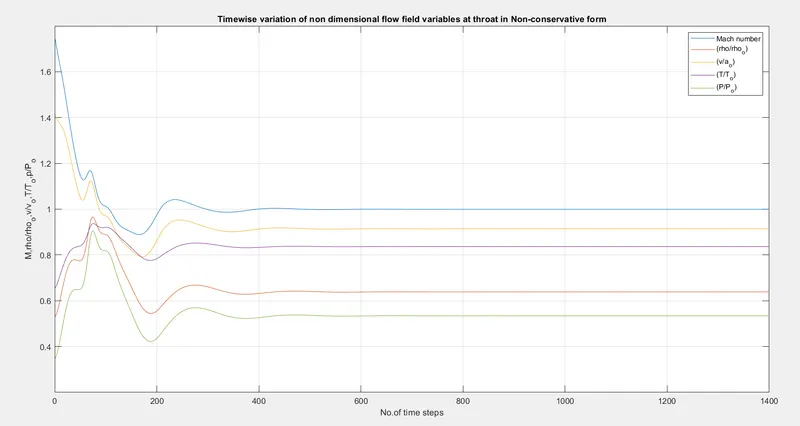
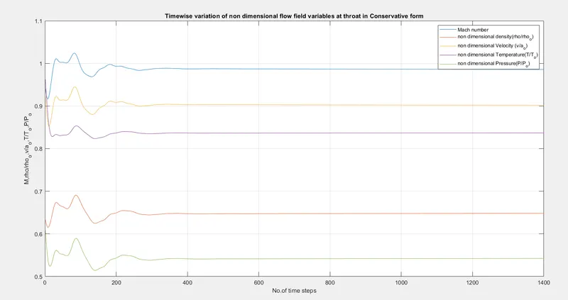
- Steady-state distribution of primitive variables inside the nozzle at throat in Non-conservative form:
- Steady-state distribution of primitive variables inside the nozzle at throat in Conservative form:
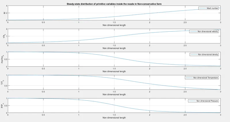
- Steady-state distribution of primitive variables inside the nozzle in Non-Conservative form:
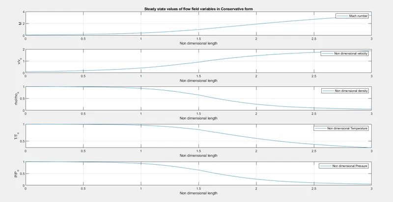
- Steady-state distribution of primitive variables inside the nozzle in Conservative form:
- Comparsion of Normalized mass flow rate distributions of Non-conservative and conservative forms:
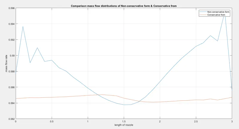
A detailed comprision of he steady-state mass flow variations obtained with the non-conservation and conservation forms of the governing flow equations. The steady-state mass flow results obtained with the conservation form are, on the whole, much closer to the exact solution of `rho' A' V' = 0.579`.
The comparison shown in the above plot illustrates a general advantage of the conservation form of the equations. The conservation form does a better job of preserving mass throughout the flow field, mainly because the mass flow itself is one of the dependent variables in the equations, the mass flow is a primary result from these equations. In contrast, the dependent variables and the mass flow is obtained only as a secondary result. Becaues the conservation form of the equations does a better job of conserving mass throughout the flow field, we can begin to understand why they are labeled the conservation from.
Simulation Time:
Iteration time of Non-conservative from is (Time_Nc) = 1.6642 sec
Iteration time of Conservative from is (Time_C) = 3.1742 sec
Grid independence test:
For No.of grid points (n) = 31
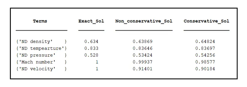
The obtained solution results are approximately matching with the exact solution, hence the grid can be considered as grid-independent.
Note that the non-conservation form results are distinctly closer to the exact values. By doubling the no.of grid points, the steady-state numerical results are slightly closer to the exact, analytical values but not as close as the non-conservation form results with half as many grid points. For all practical purposes, we have grid ondependence with 31 grid points.
Conclusion:
After the completion of simulation and observing the results we can finally conclude that for the given flow problem, we cannot establish a clear superiority of the conservation form of the governing equations over the non-conservation form.
Observations:
- The conservation from yields a better mass flow distribution. The conservation form simply doesa better job of conserving mass since the mass flow itself is a dependent value.
- There is no clear superiority of either form in terms of accuracy of the results. The non-conservtion form seems to produce slightly more accurate results for the primitive variables and the conservation form seems to produce slightly more accurate results for the flux variables. The results in either case are certainly satisfactory.
- Comparing the amount of calculational effor to achive a solution, we note that the solution of the conservation form requires marginally more work. Most of this is due to the need to decode the primitive variables from the flux variables. Such decoding is not necessary when you are solving the nonconservation form.
- Non-conservation form attains steady-state faster than the conservation form
- Both the forms are grid independent.