Challenge: DC-DC Converter
1. Tune Compensator for DC motor using Bode Diagram Graphical Tuning
`G(s)= (1.5)/(s^2+14s+40.02)`
Rise time of less than 0.5 sec
Steady state error of less than 5%
Overshoot of less than 10%
Gain Margin is greater than 20db
Phase Margin is greater than 40 deg
By seeing the transfer function, one can understand it is second order LTI system. The poles and zeros determine the characteristics of the system. To find poles of system, the roots of characteristics equation must be equated to zero.
`s^2+14s+40.02=0`
`(s+10)(s+4)=0`
`s=-10,s=-4`
The poles are at -10 and -4 on the left side of s-plane. Thre is no Zero. The system is stable second order system.
Rise Time: Time taken for the system response to reach 100% of its final value for the first time.
`t_r=4/(omega_n epsilon`
Peak Time: Time taken for the system response to reach peak value for the first time.
Peak Overshoot: Peak overshoot is the peak value of the response curve measured from unity.
`M_p=(y(t_p)-y(t_infty))/(y(t_infty))*100%`
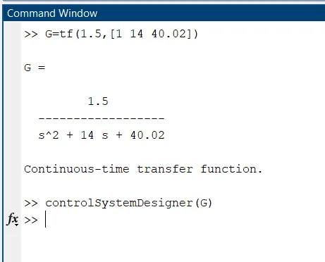
The compensator is designed to meet the shortcomings of desired performance of the plant. To design the compensator, define the plant transfer function in MATLAB window.
Open the control system designer window for the defined transfer function by using 'control system designer command'.
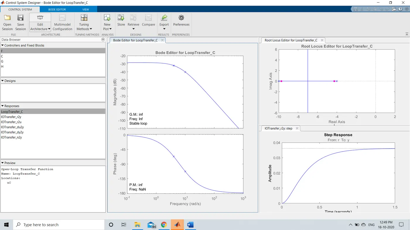
The control system designer window displays the BODE plot editor and Root locus editor side by side along with step response. One must tune the compensator to satisfy the condition of design requirements. On bode plot editor, the magnitude plot needs to be adjusted to around 4 rad/sec to get rise time and overshoot as per the condition.
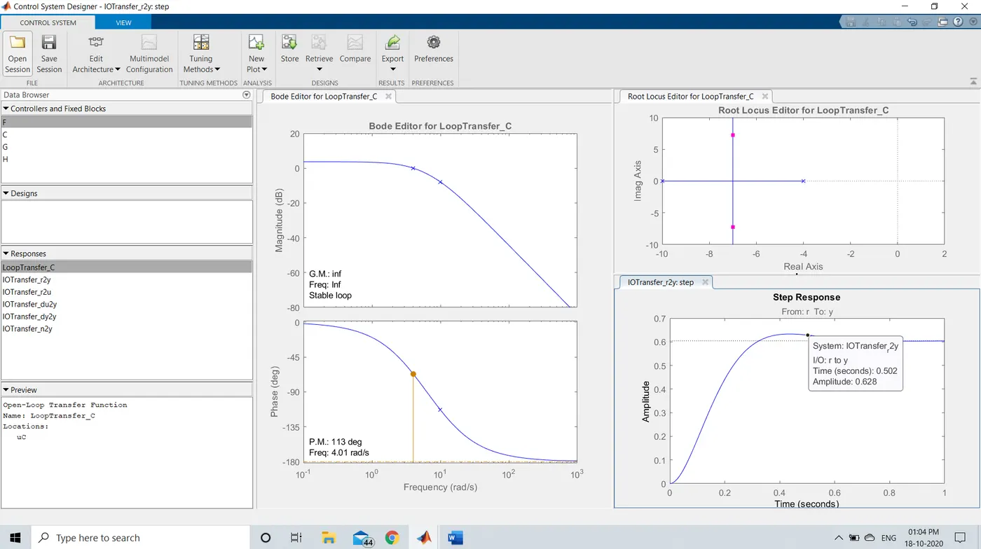
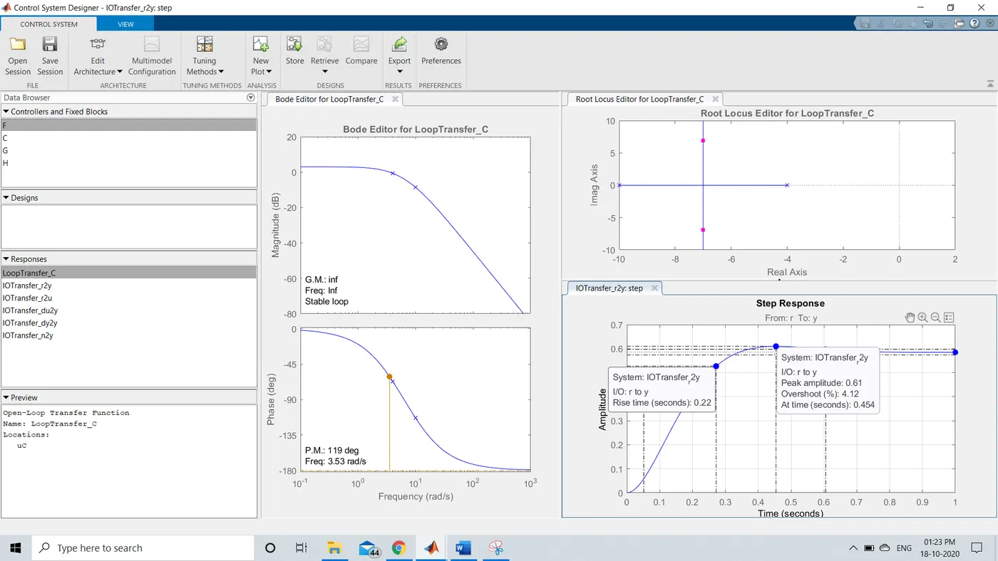
The Rise time and Overshoot have got satisfied now. To achieve 5% of steady state error, the integrator must get added by right clicking the Magnitude plot of Bode plot editor as shown below.
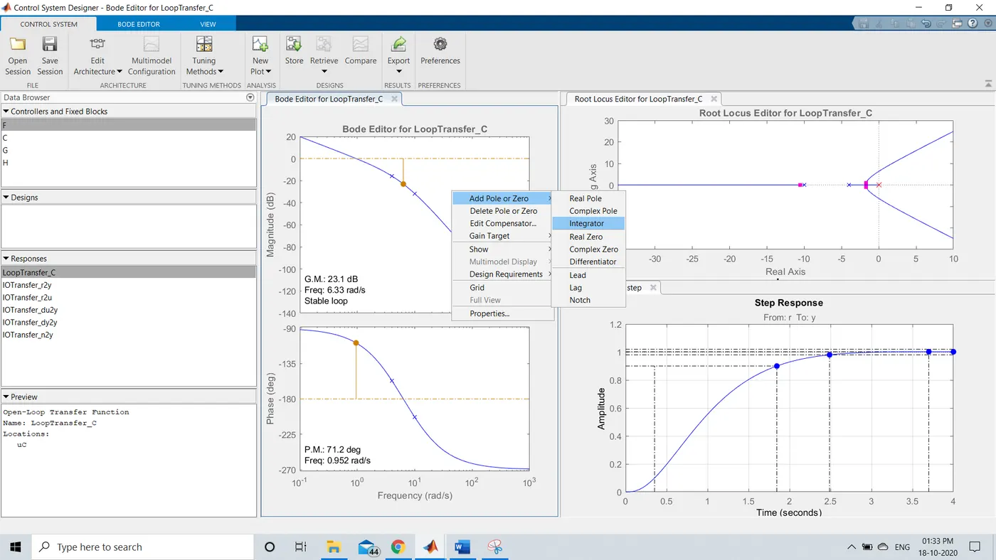
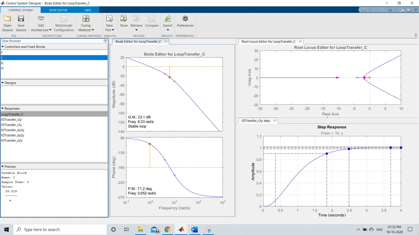
The gain of the compensator is increased directly by selecting Edit compensator. We can calculate the gain of the value.
`e_(ss)=lim_(s-0) s*E(s)=lim _(s-0)s1/(1+k*G(s))R(s).`
The gain value can be increased to 100. The lead compensator can be aded with pole at -25 and 0 at -5. Lead compensator will reshape the frequency-domin plot by providing sufficient phase lead angle over some appropriate frequency range to offset the excessive phase lag associated with the plant. The transfer function of lead compensator is
`D(s)=(taus+1)/(tau alphas+1) alpha<1;tau>0`
Now the design requirements have been satisfied.
----------------------------------------------------------------------------------------------------------------------------------------------------------------------------------------------------------------------------------------
2. Can a system with pole on right half of the s-plane be stable? Justify your answer with an example
Ans: No, system with pole on right half of the s-plane is unstable.
Stability: A system is said to be stabile if the bounded inputs there exist bounded outputs.
Case 1:
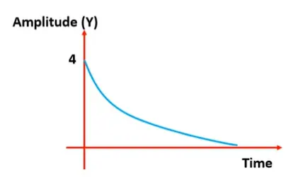
Let us consider a signal `4e^(-2t)`
Let `y=` `4e^(-2t)`
when `t=0` we get `y=4`
when `t=infty` we get `y= 0`
at t=0 and `infty` we have finate values, therefore the system is stable.
Now, let us plot the signal
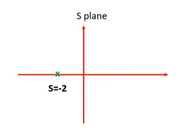
Laplace transformation of `6e^(t)` is `6/(s+2)`
`therefore implies s=-2`
Case 2:
Let us consider a signal `e^(2t)`
Let y= `e^(2t)`
`t=0` we get `y=1`
`t=infty` we get `y= infty`
at t=`infty` we have infinate values, Therefore the system is unstable.
Now, let us plot the signal
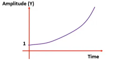
Laplace transformation of `e^(2t)` is `1/(s-2)`
`therefore implies s=2`
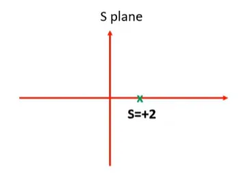
Therefore the system with pole on right half of the s-plane is unstable.
-----------------------------------------------------------------------------------------------------------------------------------------------------------------------------------------------------------------------------------------
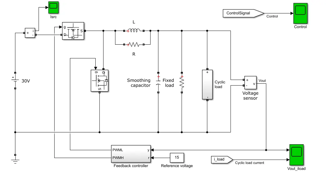
3. Make a model of closed loop voltage controlled DC-DC converter. Determine suitable PI gain values to track the output voltage set point. Changing the supply voltage, load and switching frequency requires modifications in PI gain values?
Synchronous Buck (DC-DC) Converter:
Feedback controller system:
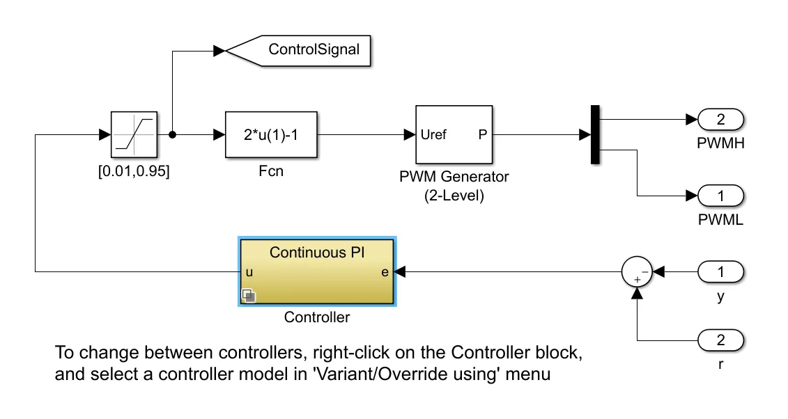
This switched power supply converts a 30V DC supply into a regulated 15V DC supply. The model can be used to size the inductance L and smoothing capacitor C, as well as to design the feedback controller. By selecting between continuous, discrete time, and fixed-point PI controllers, the impact of discretization and using limited numerical precision can be explored.
Refer to the elec_switching_power_supply example model for a detailed version that uses N-Channel MOSFETS to capture the switch-on/switch-off timing of the devices, this depending primarily on the gate capacitance values and the PWM driver output resistance.
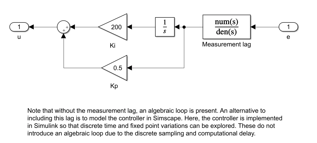
The sutable PI gain values to track the output voltage set point are :
Results:
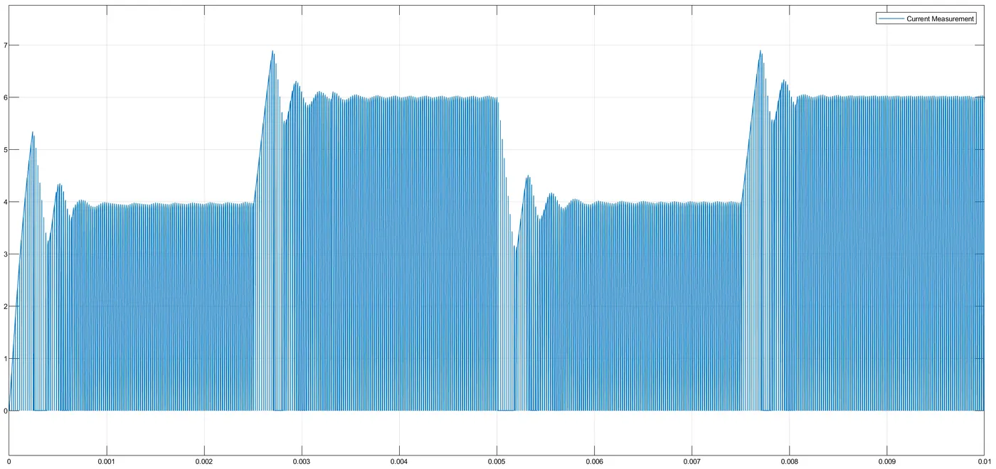
Input current:
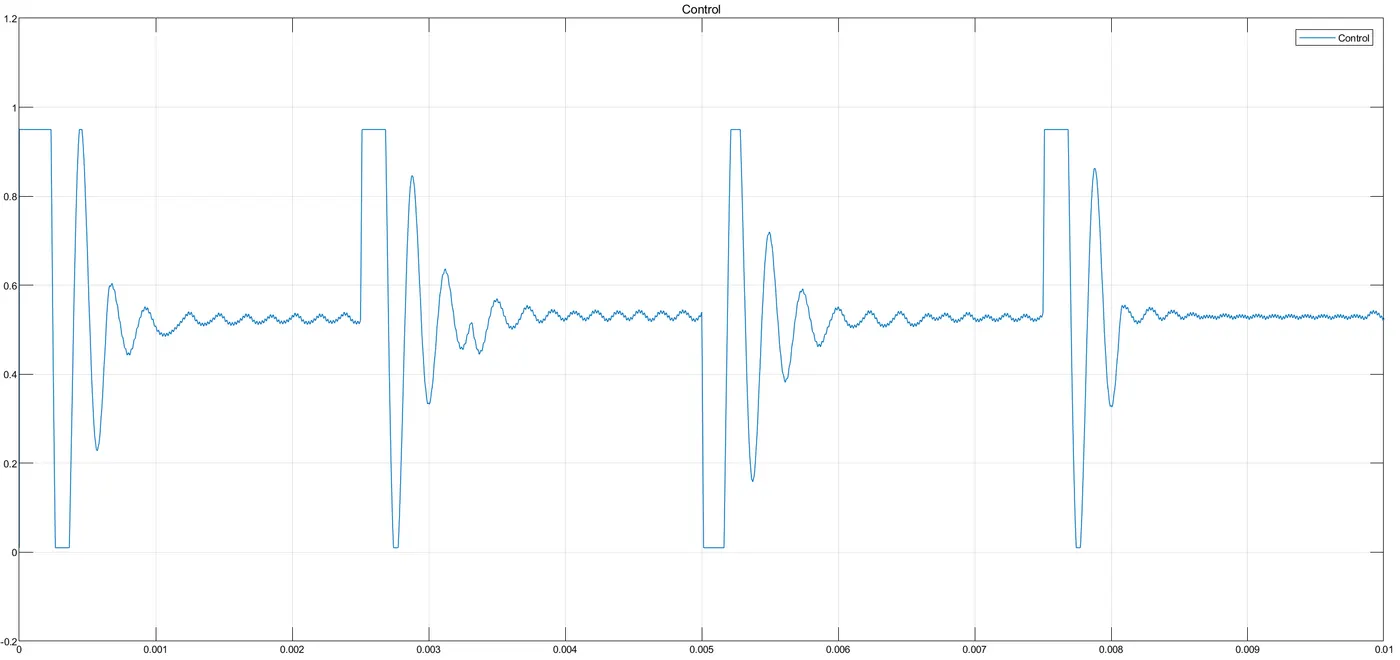
Control signal:
Output voltage and cyclic load current:
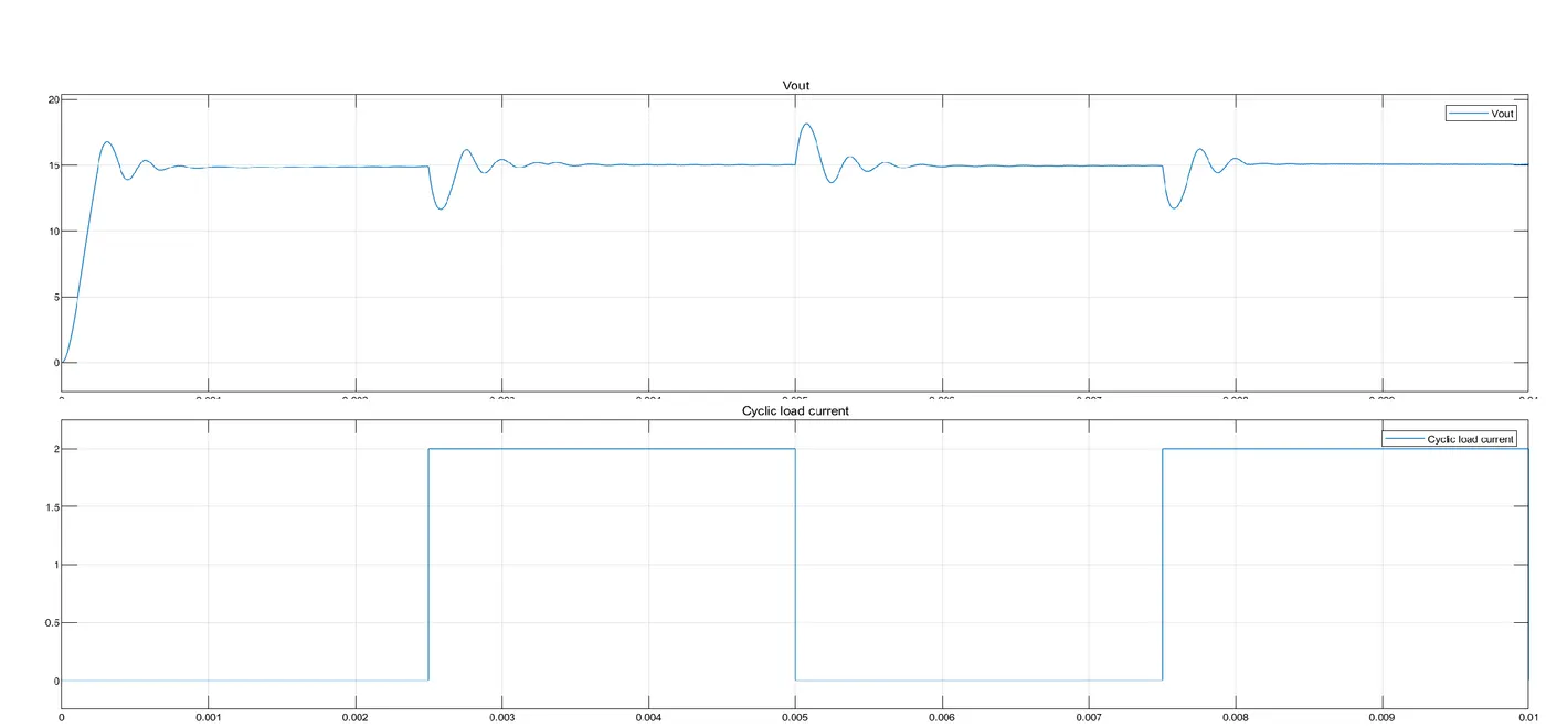
No, Changing the supply voltage, load and switching frequency dosen't requires modifications in PI gain values.