Thermal Management of a Battery pack
Aim:
To Simulate MATLAB BMS_Closedloop model.
Software used:
MATLAB R2020a (Simulink)
Battery Management System:
The battery management system (BMS) is responsible for safe operation, performance, and battery life under diverse charge-discharge and environmental conditions. When designing a BMS the cell voltage and temperature, state of charge, state of health and the charging profile has to be controlled and maintained. Also, it indicates whether there has been a fault, for example that any cell has reached an over-temperature condition or under-voltage condition (Under-voltage occurs when the average voltage of a system drops below intended levels. It is usually caused by undersized or overloaded utility). Lithium-ion battery packs are the widely used energy storage systems in electric vehicles.
The primary functions of the BMS for an EV are:
- Safety
- Performance Optimization
- Health monitering and diagnostics
- Communication
BMS_Closedloop_Harness_Dashboard:
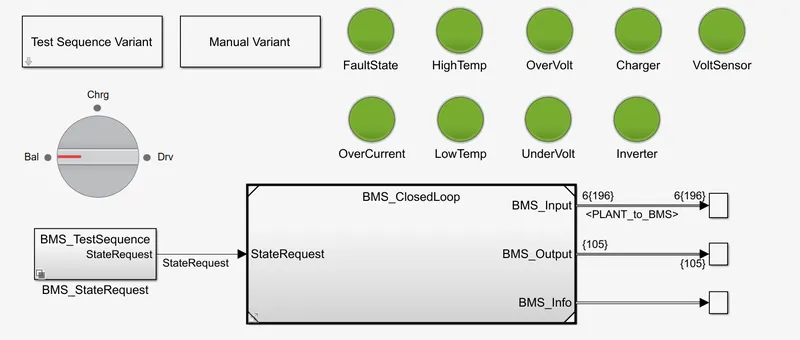
The model here allows the user to know the error by glowing the RED light on the dashboard. If there are no defects the lamps will indicates GREEN light.
The various defects that can occur are
- Fault State
- Over current
- High Temperature
- Low Temperature
- Over Voltage
- Under Voltage
- Charger
- Inverter
- Voltage sensor
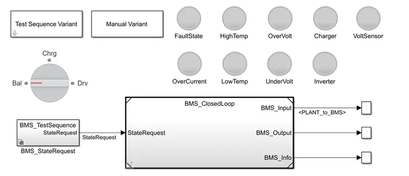
The BMS_Closedloop_Harness_Dashboard consists of Test sequence variant, Manual variant, MBS_StateRequest and BMS_Closedloop.
From 'Test sequence variant' will select the Test Case 1, 2, 3.
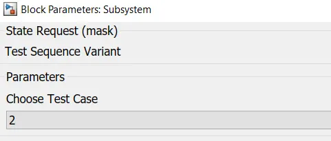
From 'MBS_StateRequest' will check the progress of the simulation.
BMS_ClosedLoop:
It is comples arrangement. Here will have two main blocks.
- BMS_ECU
- PLANT
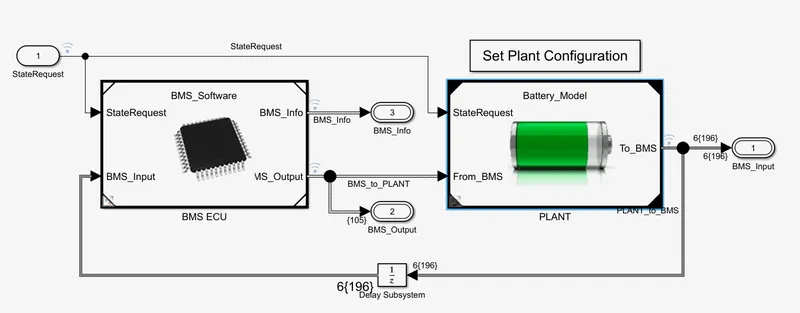
The plant is actually the battery, and the BMS_ECU is a battery management system mainly implemented as a software in a simulation environment in the MATLAB.
First will see about PLANT Block.
PLANT:
PLANT is a system which consists that Battery pack, Precharger circuit along with charger and inverter system. Use of precharge circuit is to prevent sudden rise up in current with varying load demands. There are two types of battery pack arrangement we can select a 1 module pack of 6 cells in series and 16 module pack of each consist od 6 cells connected in series. Hence 16 module pack have 96 cells which can be used for high power requirements. The inverter circuit is fed with the load signal which describes the current requirement from the battery pack during driving condition.
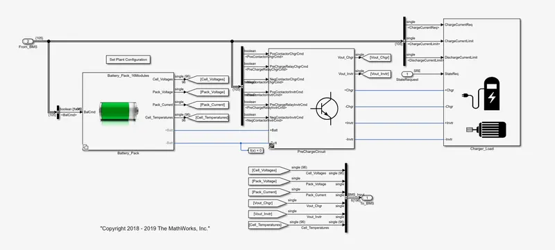
The charger and the load is a system where you have the motor through the inverter, connected with the +Invtr & -Invtr and the charger connected with the +chgr & -chgr.
Usually in EV/HEV, 3-phase Induction motor were used, that will required inverter to run it from a DC source.
Charger Circuit:
The charging happens at continuous rate and this is based on a typical value in 'Convert' block. So, constant current is implements over here.
DriverLoad Circuit:
This is not an actual driver. This is implementing a battery current from a drive cycle. This drive cycle is a repeting table, which includes time and data values given in the script file.
This will discharge like motor and an inverter.
Precharger Circuit:
Basically precharger circuit is going to connects and disconects the precharge resistor for an inverter or for a charger.
There are 2 resistors connected together because the current is reverse, there may be two resistors required.
Battery pack:
Battery pack model contains two systems.
first system is 1 module of 6 cells connected in series connection and another one is 16 modules each having 6 cells which results into 96S cells.
BMS_ECU:
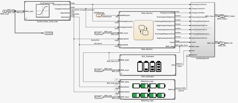
Here we have battery functionalities, The BMS functionalities are implemented in a state machine diagram.
Here we have the five main systems.
- Current & power limit calculation
- State machine
- SOC estimation
- Balancing logic
- Bus Management
Current & power limit calculation:
Here the discharge current and charge current limit is calculated.
Based on 6 no. of cells conected in series and based on the minimum and maximum cell voltage, current and temperature this limits are calculated.
State Machine:
State Machine defines the main operating state of the BMS. The state machine has four parallel states (parallel meaning that they can be active at the same time):
a.) The first one defines the variable BMS_State which indicates standby, driving, charging, and fault. Charging comprises constant current and constant voltage stages.
b.) The second state switches the fault state ON in case a current, voltage, or temperature value reaches an unsafe level.
c.) The third and fourth states define the contactor ON and OFF switching sequence for the charger and inverter. This is needed to avoid an excessively large current inrush at the beginning of the charging stage.
SOC estimation:
This SOC estimation works on three different formates. They are Coulomb counting, UKF and EKF.
Coulomb counting is the integration of current over the time. It is done in discrite time integrator. In this Z-domain integrator gives the idea about the SOC.
The Extended kalman filter (EKF) and UKF two different algorithms and these two kalman filters are accurately calculate the SOC.
Balancing logic:
It has an algorithm that, to which cell is to be balanced. By following the given conditions this block will work.
Bus Management:
This block creates a bus signal from its inputs and provides output of current and power limit calculation, state machine, SOC estimation and balancing logic.
Simulation of BMS model:
The battery pack configuration selected for simulation is 1 module battery pack with 6 cells in series.
There are 3 test cases in the simulation and the simulation is run for all the three test cases and faults conditions are checked.
Test case 1:
Simulation analysis:
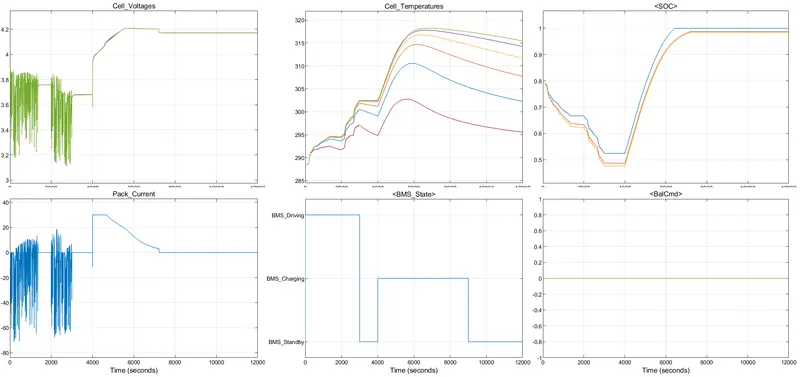
Initially for the first 3000 seconds, the BMS switches to driving condition. In this case, there is variation in battery pack current and voltage due to driving signal till 3000 seconds. There are various different cell voltages occurs in this period. The initial cell voltage is at 3.9V. SOC drops from 80% to around 50% during this period. While BMS is driving condition the temperature of cells are rising.
From 3000 - 4000 sec, the BMS comes to a standby mode since there is no driving or charging condition given. From 4000 - 9000 seconds, BMS switches to charging condition.
After 3000 seconds, Cell voltage falls to 3.7V and continues at 3.7V till 4000 seconds due to Stand-by mode. The pack current value also varies according to the load and again returns to 0A when the BMS signal turns to Stand-by mode since there is no driving or charging.
From 4000 - 9000 seconds period, the cell voltages rises gradually from 3.7V to 4.2V till 7000 seconds (Charging Mode) and then slightly drops to 4.18V after 7000 seconds and remains the same till 12000 seconds. During this period, the pack current rises step to a value of 30A and then gradually falls back to 0A during the charging mode, follower by Stand-by modeand continuous the same till end of the simulation.
From 4000 - 4500 seconds the current is constant by the voltage is increasing from 3.85V to 4.2V, Hence, this is called constant current charging (CC). Once cell reaches to 4.2V, then it was constant voltage charging (CV). We can observe here, that the constant voltage charging is taken more time than constant current charging. During constant the SOC is rised quickly.
The SOC rised from 50% to 100% during charging condition and reached upto 100% around 9000 seconds and stays the same same throughout the stand-by period till end. The 'Blue line' indicates the Coulomb counting method and 'Yellow & Orange' indicates EKF and UKF methods.
There is no fault condotions observed during simulation of Test Case 1.
Test case 2:
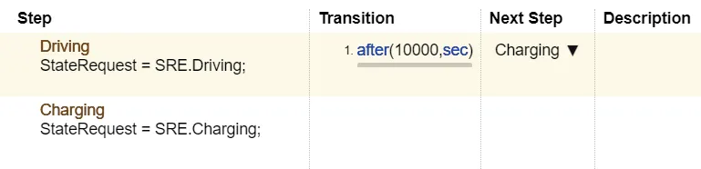
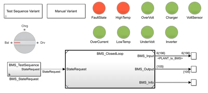
Simulation analysis:
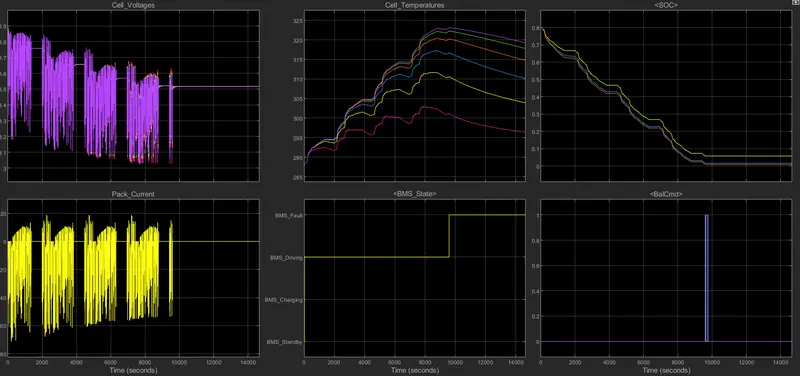
Initlally for the first 10000 seconds, the BMS system follows the Driving mode followed by charging till the end of the simulation.
During the simulation, at around 9500 seconds, the cell temperature of cell number 6, reaches a value more than the permissible range and hence a fault signal is produced by the BMS. Also the SOC of the pack also reaches to 15% which is very low. Till the cell temperature reached the maximum limit, the variation in the pack current and cell voltages can be observed and then current is become 0A and voltage is 3.6V.
At the instant where BMS trigger the fault, there is a balancing command pulse which is also observed.
In this Test Case, a High Temperature fault is observed due to continuous usage of the battery pack over a long period of time. This high temperature is due to the internal resistance loss of the battery as current flows through the battery for a very long period of time. The negative current represents the discharging of battery.
Test case 3:

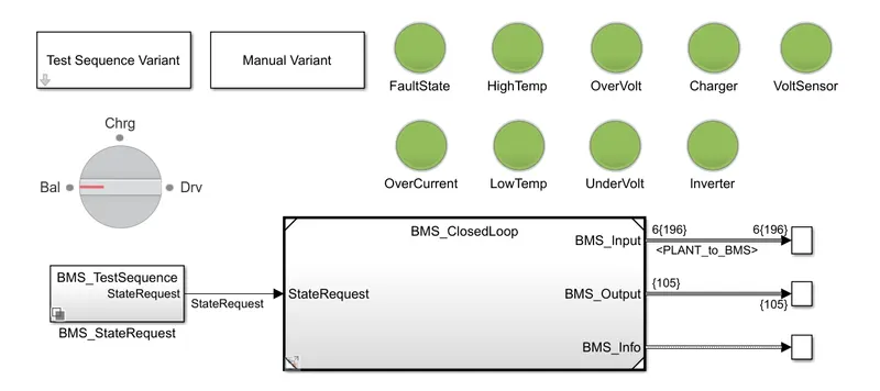
Simulation analysis:
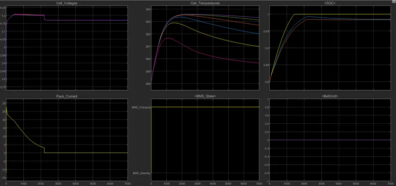
Test Case 3 only focuses on the charging condition through the simulation period. Initially the battery pack is having around 80% of charge left. Charging for 1400 seconds makes the battery pack fully charged. The cell voltage rises to value above 4.2V within 500 seconds of charging and then stays constant till 2200 seconds and suddenly drops to 4.17V also pack current drops to 0A at teh same time and then continuous same till the end of the simulation.
The cell temperature incresed initially and gradually reduced. The highest cell temperature is 293.5K whenthe cell reach around 100% SOC and then gradually reduced as charging continuous.
There is no fault observed during this Test Case 3 with charging mode throughout the simulation.
Observation:
The Battery ClosedLoop Harness Dashboard model is simulated with 3 predefined test sequences.
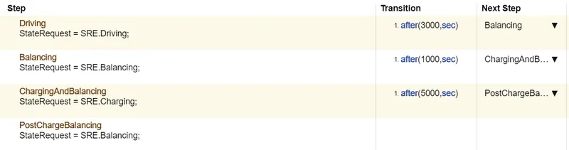
Test Case 1: Includes Driving condition, Balancing condition and Charging conditions with transition occuring at specific time intervals.
Test Case 2: Includes Driving followed by Charging condition with transition occuring at defined time intervals.
Test Case 3: Includes only Charging condition throughout the simulation period.
Conclusion:
The BMS Closedloop model is simulated with 3 different modes of usage/ Test cases. The simulation results exhibit that the Test case 2 is having a very long duration for driving condition tends to create very High Temperatures in cells during the simulation which is identified by the battery management system and given a fault alaram to the user.
Hence, Simulated the MATLAB BMS_Closedloop model to check the faults and analysed the results. This is the BMS complete simulation in MATLAB is going to support the hardware in the loop testing aswell by solving the temperaute faults in the Test case 2. The only thing to note is that we have to connect microcontroller with the MATLAB embeded coder.