Mathematical Model of Lead - acid Battery.
Aim:
To make a MATLAB script for the mathematical model of lead acid battery.
Software used:
MATLAB R2020a
Introduction:
The lead–acid battery was invented in 1859 by French physicist Gaston Planté and is the earliest type of rechargeable battery. Despite having a very low energy-to-weight ratio and a low energy-to-volume ratio, its ability to supply high surge currents means that the cells have a relatively large power-to-weight ratio.
The battery which uses sponge lead and lead peroxide for the conversion of the chemical energy into electrical power, such type of battery is called a lead acid battery. The lead acid battery is most commonly used in the power stations and substations because it has higher cell voltage and lower cost.
Lead-acid batteries use lead as annode material and lead dioxide as a cathode material and the Sulphuric acid is used as a electrolyte. Absorbed glass mat (AGM) is used as a separator.
The chemical reaction of Lead-acid battery is `PbO_2+Pb+H_2SO_4 Leftrightarrow 2PbSO_4+2H_2O`
Working Principle of Lead Acid Battery:
When the sulfuric acid dissolves, its molecules break up into positive hydrogen ions (2H+) and sulphate negative ions (SO4—) and move freely. If the two electrodes are immersed in solutions and connected to DC supply then the hydrogen ions being positively charged and moved towards the electrodes and connected to the negative terminal of the supply. The SO4— ions being negatively charged moved towards the electrodes connected to the positive terminal of the supply main (i.e., anode).
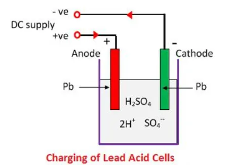
Each hydrogen ion takes one electron from the cathode, and each sulphates ions takes the two negative ions from the anodes and react with water and form sulfuric and hydrogen acid.
The oxygen, which produced from the above equation react with lead oxide and form lead peroxide (PbO2.) Thus, during charging the lead cathode remain as lead, but lead anode gets converted into lead peroxide, chocolate in colour.
If the DC source of supply is disconnected and if the voltmeter connects between the electrodes, it will show the potential difference between them. If wire connects the electrodes, then current will flow from the positive plate to the negative plate through external circuit i.e. the cell is capable of supplying electrical energy.
Chemical Action During Discharging:
When the cell is full discharge, then the anode is of lead peroxide (PbO2) and a cathode is of metallic sponge lead (Pb). When the electrodes are connected through a resistance, the cell discharge and electrons flow in a direction opposite to that during charging.
The hydrogen ions move to the anode and reaching the anodes receive one electron from the anode and become hydrogen atom. The hydrogen atom comes in contacts with a PbO2, so it attacks and forms lead sulphate (PbSO4), whitish in colour and water according to the chemical equation.
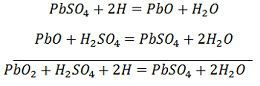
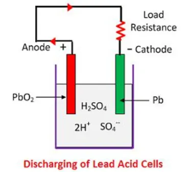
he each sulphate ion (SO4—) moves towards the cathode and reaching there gives up two electrons becomes radical SO4, attack the metallic lead cathode and form lead sulphate whitish in colour according to the chemical equation.
Chemical Action During Recharging:
For recharging, the anode and cathode are connected to the positive and the negative terminal of the DC supply mains. The molecules of the sulfuric acid break up into ions of 2H+ and SO4—. The hydrogen ions being positively charged moved towards the cathodes and receive two electrons from there and form a hydrogen atom. The hydrogen atom reacts with lead sulphate cathode forming lead and sulfuric acid according to the chemical equation.
`PbSO_4+2H_2O+H =PbSO_4+2H_2SO_4`
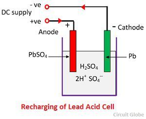
SO4— ion moves to the anode, gives up its two additional electrons becomes radical SO4, react with the lead sulphate anode and form leads peroxide and lead sulphuric acid according to the chemical equation.
`PbSo_4+2H=H_2SO_4+Pb`
The charging and discharging are represented by a single reversible equation given below.
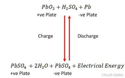
The equation should read downward for discharge and upward for recharge.
Definations and Governing equations:
Open Circuit Voltage (E):
Open circuit voltage is a maximum theorital voltage that an battery can achieve. This voltage is not possible in actual conditions because of losses and internal resistance of the battery. OCV can be approximated by discharging the battery at a very low discharge rate (i.e.; around C/20).
State of Charge (SoC):
SOC of a battery is defined as the ratio of its current capacity `Q(t)` to the nominal capacity `Q_n.`
SoC shows how much charge/energy is available in the battery at a given instant of time. SoC ranges from 0 to 100%.
SoC value depends on the previous behaviour(Hysteresis) of the battery and be calculated as, `SoC= (Q(t))/Q_n *100` where `Q` is the capacity.
Depth of discharge (DOD):
It shows that amount of energy removed from a battery at a given instant of time
DOD= Charge removed/Peukert's capacity
also, `DOD= 1-SoC`
Peukert's law:
Peukert's law expresses the battery capacity with respect to the rate of discharge. The law states that the discharge capacity of the battery dereases with the increase in the rate of discharge current.
`C_p=I^k*T`
where I = Current
T= Time
k= Peukert's coefficient. This constant has a value closer to 1 (in this cas 1.045). The coefficient k corelated the current at a given time.
Charge removed:
Charge removes ia the amount of energy removed from the total stored energy in the battery. The amount of energy removed is higher than the actual amount of energy supplied to the system. The charge removed also dependes on the behaviour of the battery in an earlier time step.
`CR=CR_(earlier-time-step)+(I^k*dt)/36000`
Charge supplied:
Charge supplied is the actual amount of energy or charge supplied to the system from the battery. The charge supplied is always less than the charge removed and depends on the earlier time step behaviour.
`R=CR_(earlier-time-step)+(I^k*dt)/3600`
MATLAB Code:
%Mathematical Model of Lead-Acid battery
clear all
close all
clc
%Defind inputs
%Defining time steps in variable T
T= (0:50:500000); %Total time 10001 steps with each time space of 50 sec.
CR= zeros(1,length(T)); % Charge removes (CR)
DOD= zeros(1,length(T)); %Depth of discharge
V= zeros(1,length(T)); % Voltage
CS= zeros(1,length(T)); %Charge supplied
E= zeros(1,length(T)); % Operating circuit voltage
I=[10,50,100,150,200]; %Current in Amphers
n=1; %No.of cells
C=50; %Capacity in Ah
k=1.045; %.045 represents loss of capacity due to discharge
dT= (T(2)-T(1))* ones(1,length(T)); %Time step
R_in= (0.06/C)*n; %Internal Resistance
E(1)=2.15;
for i= 1:length(I)
    V(i)=n*(2.15-I(i)*R_in);

%Define the voltage equation for OCV
for n= 2:length(T)
    dT(n)= T(n)-T(1);
    Cp=(I(i)^k)*(dT(n)); %Peukert's capacity
    CR(n)= (CR(n-1)+(dT(n)*(I(i)^k))/3600);
    DOD(n)=(CR(n)/Cp);
    E(n)=2.15-DOD(n)*(2.15-1.75);
    V(n)=E(n)-I(i)*R_in;

    if DOD(n)>0.99
        E(n)=0;
        V(n)=0;
    end
    if DOD(n)>1
        DOD(n)=1;
    end
    if E(n)>0
        CS(n)=CS(n-1)+((I(i)*dT(n))/3600);
    else
        CS(n)= CS(n-1);
    end
end
figure(1)
hold on
plot(DOD,V)
xlabel('DOD')
ylabel('Voltage')
end
plot(DOD, E)
legend('E-OCV','V-Voltage','I=10A','I=50A','I=150A','I=200A')
grid on


figure(2)
plot(DOD,E)
hold on
plot(DOD, V)
legend('E-OCV','V-Voltage')
xlabel('CR')
ylabel('Voltage')
grid on

figure(3)
plot(CR,E)
hold on
plot(CR, V)
legend('E-OCV','V-Voltage')
xlabel('CR')
ylabel('Voltage')
grid on

figure(4)
plot(CS,E)
hold on
plot(CS, V)
legend('E-OCV','V-Voltage')
xlabel('CS')
ylabel('Voltage')
grid on
Procedure:
- Initially defined the time step, Total time 10001 steps are defined with each time space of 50 sec.
- Defined the variables for mathematical model of CR, CS, DOD, V, Cp, E, n, I, C, k for improving the performance of the simulation.
- I is the discharge current and is taken as 10, 50, 100, 150, 200. This are the diffenent discharge rates as C/5, 1C, 2C, 3C and 4C.
- I used two 'for' loops for the calculation. 1st 'for' loop is used to calculate the run the inner commands for each value of discharge current I.
- Second 'for' loop is the time loop and it calculates values of CR, CS, E, V and DOD repeats the simulation till the end of the defined time steps.
- 'if'loops are used such that voltage and OCV will drop when DOD reaches any value above 0.99 and further the value of DOD is considered as 1 (i.e.;the battery is assumed to be completely discharged).
- Next, the results are plotted using the plot command.
Results:
Open circuit voltage (E) & Battery discharge voltage (V) Vs Depth of discharge (DOD):
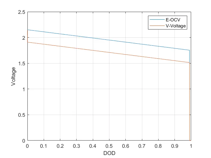
- This plot shows the variation of open circuit voltage and battery discharge voltage with respect to DOD. The difference between both the voltages is due to the internal resistance of the battery and other loose (temperature, chemistry etc).
Open circuit voltage (E) & Battery discharge voltage (V) Vs Depth of discharge (DOD) at different rates:
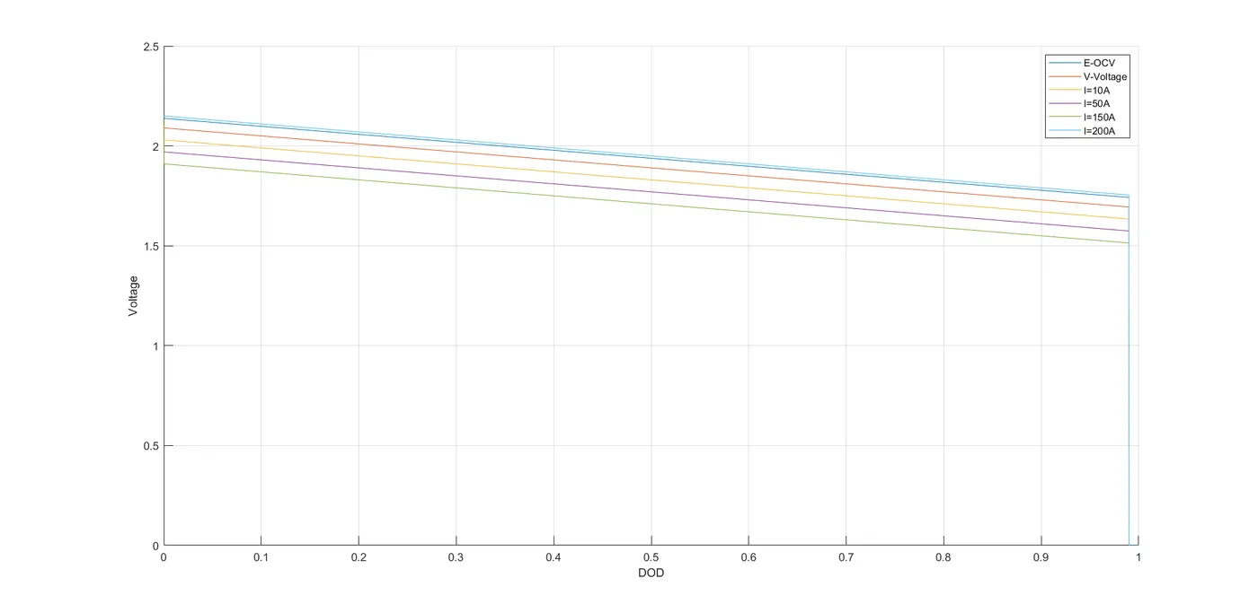
- From this plot, it shows that as the discharge rate increases the discharge capacity of the battery decreases. The topmost line is the open circuit voltage and is the maximum possible voltage that a battery can attain idealy. But in the practical life this is impossible and by decreasing the dischargingg rate a close value to OCV can be obtained.
Open circuit voltage (E) & Battery discharge voltage (V) Vs Charge Supplies (CS):
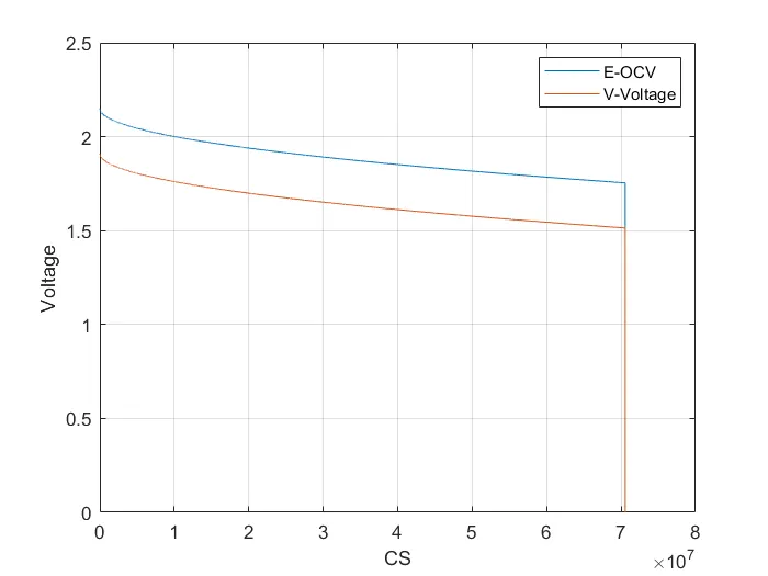
- This plot shows that the Open circuit voltage (E) & Battery discharge voltage (V) with respect to Charge Supplies (CS).
Open circuit voltage (E) & Battery discharge voltage (V) Vs Charge removed (CR):
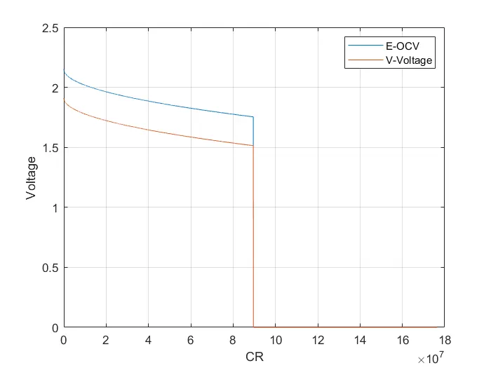
- This plot shows Open circuit voltage (E) & Battery discharge voltage (V) with respect to Charge removed. It can see that the charge removed is higher than charge supplied.
Conclusion:
Hence created a MATLAB script for the mathematical model of lead acid battery.
Referance: