Crash test of a crash tube on a rigid wall using LS-DYNA
Aim: To simulate the crash of a crash box onto a rigid wall using LS-PrePost and LS-DYNA. To generate output blocks for global and cross-sections for shell thickness of 1.2 mm and 1.5 mm and to compare the obtained results.
PROCEDURE:
1. Import the keyword file into LS-PrePost:
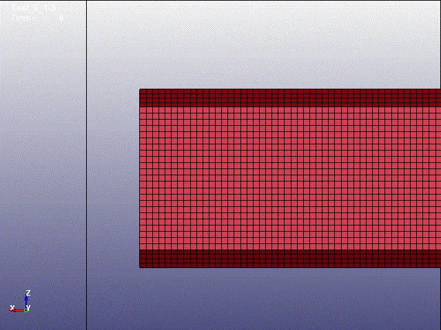
The keyword file containing the model of the crash box was imported into LS-PrePost and it looks as follows:
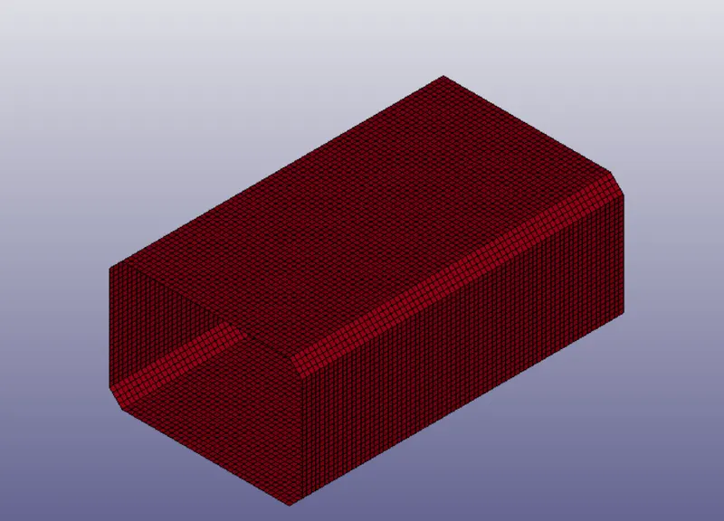
The unit system followed in the present simulation is [g mm ms].
2. Create a rigid wall:
The rigid wall was constructed in from of the crush box with a dimension of 200 mm x 200 mm. Rigid wall was constructed in LS-PrePost by going to Model and Part => Keyword manager => Rigid Wall => Geometric_Flat_Display. The settings for the rigid wall creation are shown in the image below:
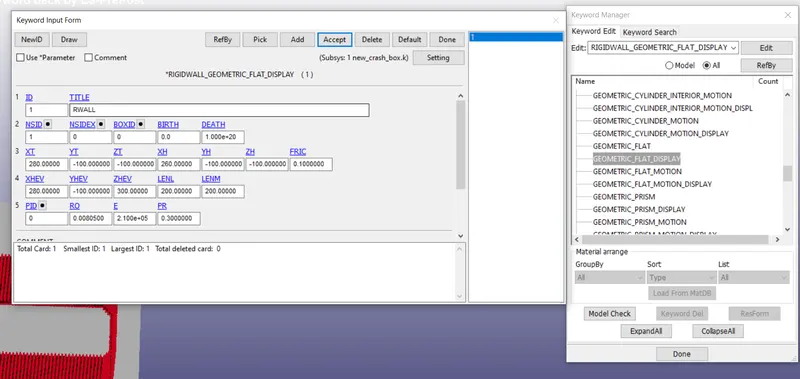
The rigid wall was constructed 30 mm in front of the crash box with respect to the x-axis.
3. Material and section properties:
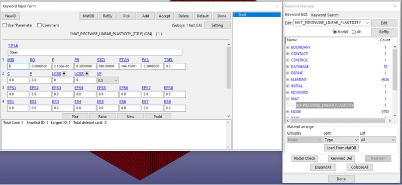
The material properties of steel were defined for the crash box with 210 GPa Young's modulus and 0.3 Poisson's ratio. A non-linear material property was given. The material property was defined by going to Keyword manager and MAT => Type024-Piecewise_Linear_Plasticity. By giving failure criteria and tangent modulus, the material was ensured to break after crossing a certain strain(2% in the present simulation). The properties assigned to the crash box are given below:
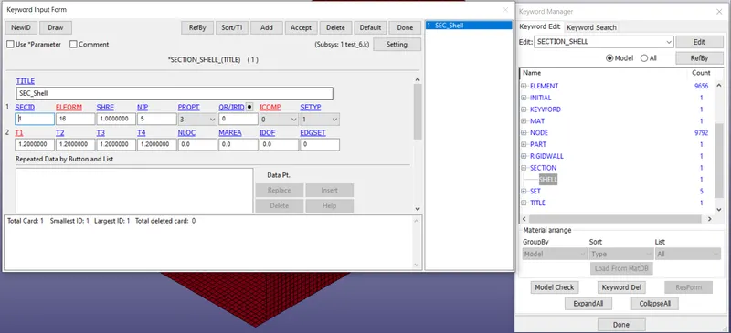
The section properties included using ELFORM = 16 for fully integrated shell element with thickness of 1.2 mm for first case and 1.5 mm for second case. The properties for section can be assigned at Keyword manager by going to SECTION => Shell. The section properties are given below:
4. Assigning self-contact:
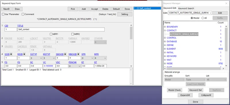
Although the rigid wall automatically sets the crash box as slave, self-contact within the crash box has to be added as well. This can be done by going to keyword manager and CONTACT => Automatic_Single_Surface. The slave and master are both given to be the crash box in order to simulate the self-contact correctly. The contact properties are given below:
5. Assigning initial velocity to the crash box:
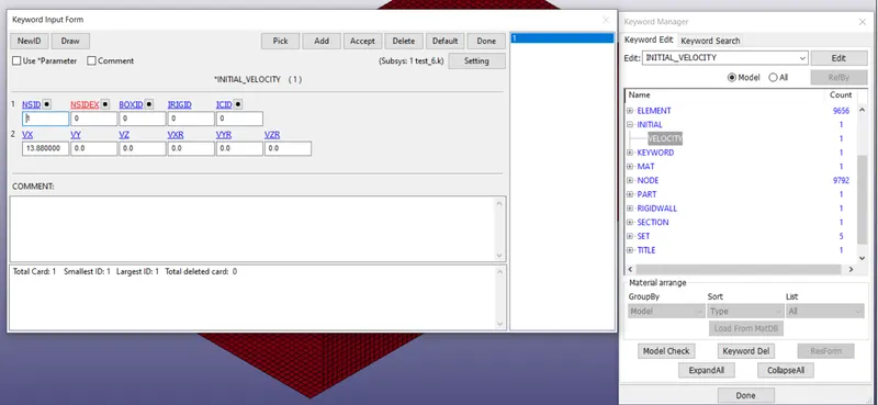
Initial velocity can be assigned to the crash box by going to Keyword manager and INITIAL => VELOCITY. %0 kmph was given which in conversion goes to 13.88 mm/ms in local unit system. The properties of initial velocity are shown below:
6. Defining output blocks:
Output blocks can be defined in keyword manager by going to DATABASE and selecting the relevant options. For ASCII outpts, GLSTAT, MATSUM, RCFORC, RWFORC, SLEOUT, SECFORC and SPCFORC were selected. For binary output, D3PLOT and D3THDT were selected. Also, a cross-section was created at the middle of the crash tube by using "Create Entity"option and cross-sectional data was also requested as output.
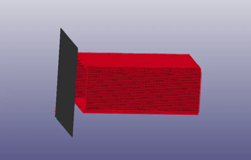
After these steps, the crash test appears like this:
RESULTS:
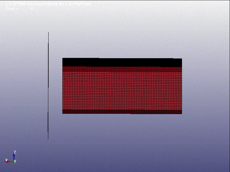
The simulation was performed using LS-DYNA and the post-processing was done once again on LS-PrePost. The crash tube was found to bounce off the rigid wall and did not buckle. The transient variation can be seen below:
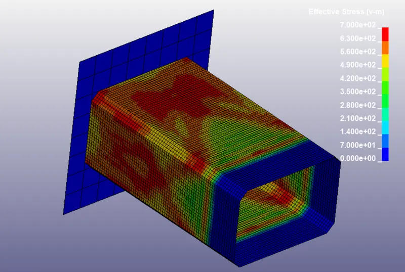
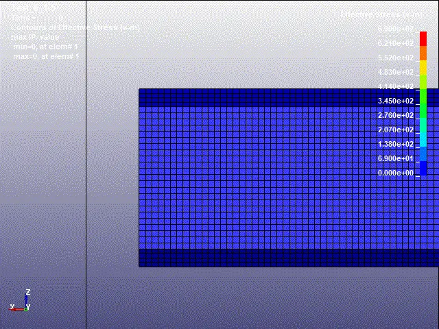
The von-mises stress peaks at 670 MPa and can be seen below during point of impact:
The internal energy, kinetic energy and total energy can be seen below:
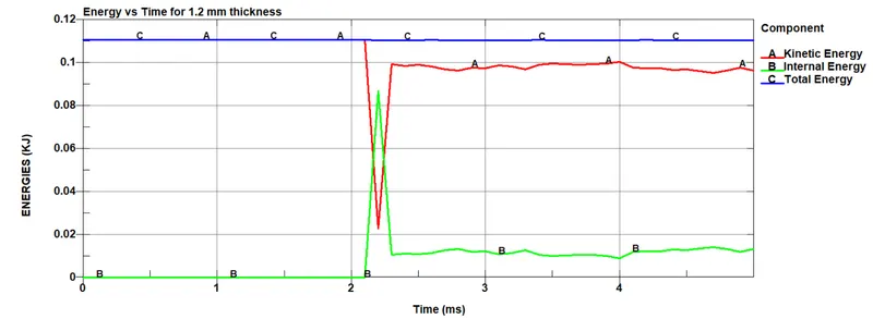
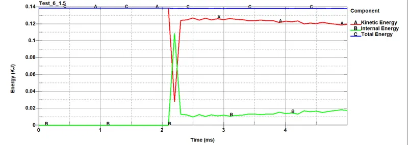
As can be seen, the internal energy is zero and kinetic energy is maximum before the crash. After impact, part of the kinetic energy is lost and is converted into internal energy. The kinetic energy is at 110 J at the beginning and after impact, it falls down to around 97 J. The internal energy starts at zero and rises to around 12.3 J after impact.
Total energy is consistent at around 110 J throughout the simulation which indicates almost no net loss of energy through dissipation or erroneous addition of energy.
Hourglass energy can be seen in the plot below:
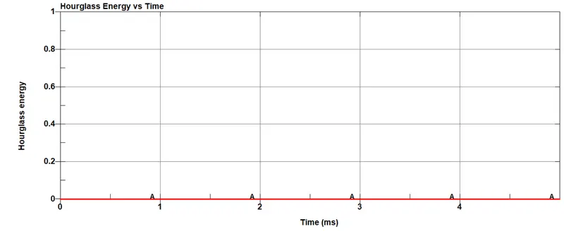
There is no generation of hourglass energy in the present simulation. This is likely due to using fully-integrated element formulation number 16 along with 5 integration points along the thickness as given in the section properties.
Velocity vs time is plotted below:
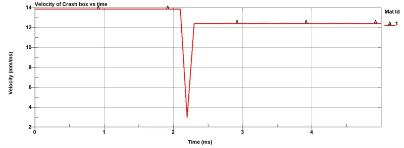
The point of impact has a clear dip in velocity following which a stable velocity is achieved with lower magnitude.
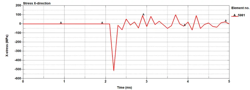
The stress about x-axis for an element lying in the front row of the crash box is given below:
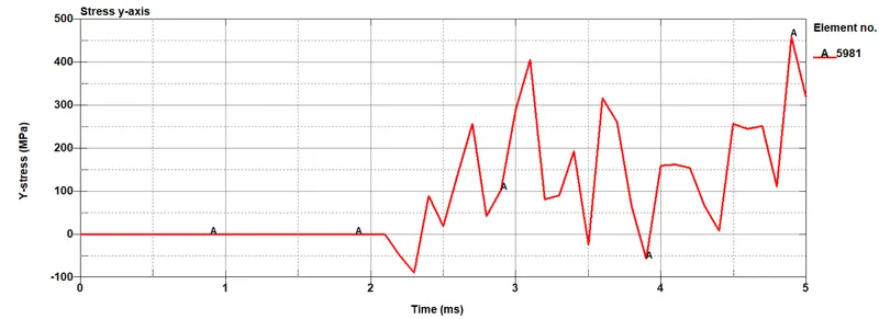
Stress about y-axis is given below:
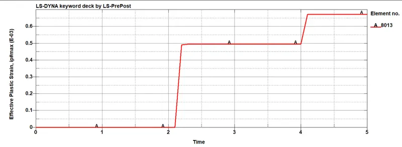
Effective plastic strain is shown below:
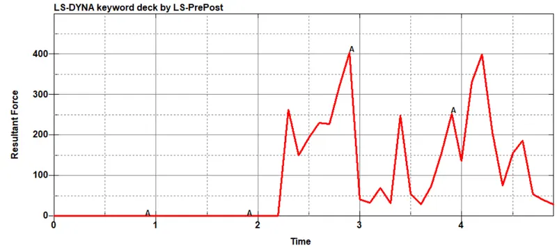
Forces at cross-section of the middle of the crash tube:
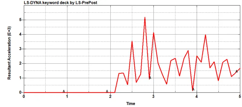
Acceleration at middle of crash tube:
Afterwards, the crash tube thickness was increased to 1.5 mm under the section properties and the following results were obtained:
Von-mises contour is shown below:
The plot for internal, kinetic and total energies are given below:
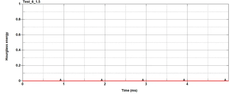
Hourglass energy variation with time is given below:
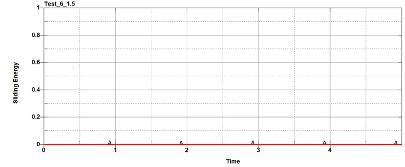
Sliding energy plot is given below:
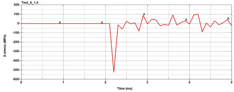
The stress experienced in the x-direction by the frontal elements is plotted vs time below:
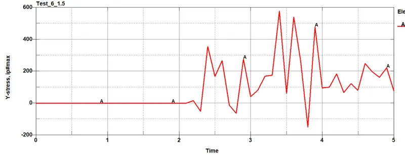
Stresses acting upon the frontal elements in the y-direction vs time is given below:
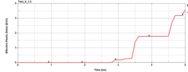
Effective plastic strain plotted vs time is given below:
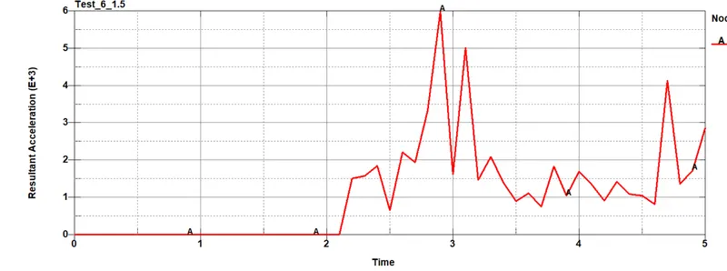
The resultant acceleration that is seen at a node in the middle of the crash box is plotted below:
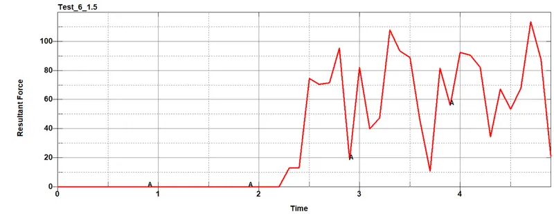
The resultant force acting upon the central elements is plotted below:
The results obtained from the two thickness values can be summarized by the following table:
|
Property |
Thickness = 1.2 mm |
Thickness = 1.5 mm |
|
Max Von-Mises stress |
670 MPa |
680 MPa |
|
Initial Kinetic Energy |
110 J |
138 J |
|
Final Kinetic Energy |
97 J |
119 J |
|
Final Internal Energy |
12.3 J |
17.6 J |
|
Max Stress – X-axis |
-514 MPa |
-524 MPa |
|
Max Stress – Y-axis |
459 MPa |
587 MPa |
|
Max effective plastic strain |
0.6 e-3 |
3.1 e-3 |
|
Maximum acceleration at centre |
5190 mm/ms2 |
6000 mm/ms2 |
|
Maximum force at center node |
400 N |
112 N |
From the table and the graphs, the following conclusions can be made:
Sliding energy and hourglass energies are both negligible in both cases. There is not enough interaction between the rigid wall and the crash box to cause a lot of friction and hourglass is zero because of the use of ELFORM = 16 fully integrated shell element with 5 integration points along the thickness.
Kinetic energy is higher for 1.5 mm thickness because higher thickness leads to more mass and therefore more kinetic energy. This increase in kinetic energy also leads to higher force upon impact which leads to an increase in Von-Mises stress despite the increase in area. This also leads to a slightly higher plastic strain on 1.5 mm thickness box when compared to 1.2 mm thick box. However, the plastic strain is negligible in both cases and is only present in the edges of the box. This is likely due to the small interaction that is present between the box and the rigid wall.
Higher stress is also seen in x-direction as well as y-direction in case of the 1.5 mm thickness box. The x-direction is compressive stress and peaks at -524 MPa whereas the y-direction stress is tensile which peaks at 587 MPa. This is again due to the higher kinetic energy with which the box impacts upon the rigid wall leading to more energy being absorbed by the box.
When the central nodes are checked for accelerations, the 1.5mm thickness box has higher acceleration at 6000 mm/`ms^2` when compared to 1.2 mm thick box with a maximum acceleration of 5190 mm/`ms^2`.
The maximum force at the centre is 400 N for 1.2 mm thick box but only 112 N for the 1.5 mm thick box. Despite higher stress at the front, the centre of the 1.5 mm thick box has a lower force acting. This is likely due to the frontal elements absorbing a larger portion of the force which leads to lower forces acting at the posterior regions of the crash box. This is the opposite in 1.2 mm box where the frontal regions due to smaller volume absorb less forces which leads to a comparatively larger force acting at the posterior regions of the tube.
Conclusion: The crash test of the crash tube with 1.2 mm thickness and 1.5 mm thickness was performed successfully. The output results were plotted, tabulated and compared quantitatively.