Structural analysis of Piston-Cam mechanism using ANSYS Workbench
AIM: To perform transient structural analysis on a piston and cam mechanism using ANSYS Workbench.
PROCEDURE:
Initially, the piston and cam mechanism model was imported to ANSYS workbench and is shown below:
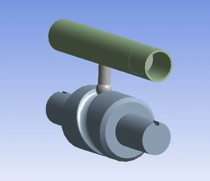
The geometry consists of a barrel, barrel cam and cam follower. The contacts provided are shown below:
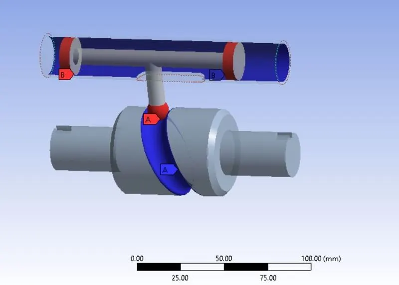
The contact properties will be changed and in each case the difference in results will be noted. The barrel is fixed using fixed joint as shown below:
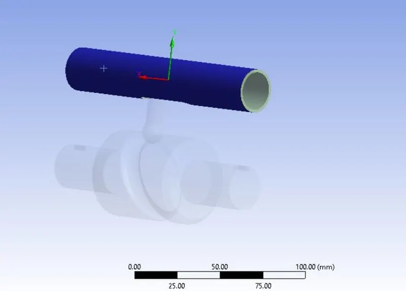
The barrel cam is given a revolute joint as shown below:
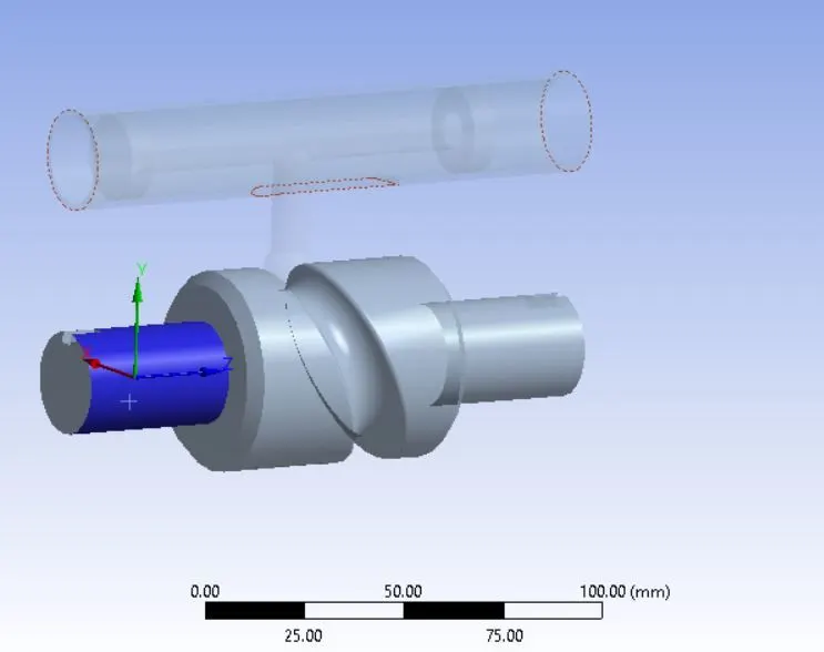
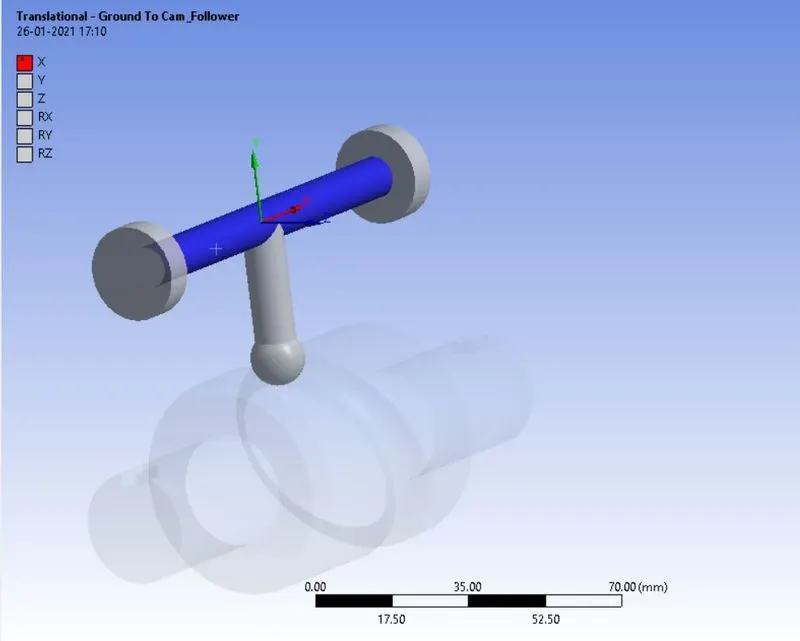
The cam follower is given a translational joint and is shown below:
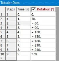
The revolute joint is given joint load in the form of rigid rotation with 9 steps. Each step rotates the joint by 30 degrees as shown in the table below:
The rotation of the barrel cam will cause the translation of the cam follower. In each case the simulation is solved for directional deformation, stress and elastic strain while changes are made to the contact type.
CASE 1: Contact type = Frictionless:
In first case, the contact is frictionless. Therefore, the surface offers no resistance to motion. The deformation contour in x-direction which is the direction of translation for the cam follower is shown below:
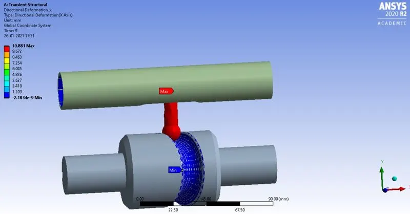
Maximum deformation of 20.352 mm is observed. The stress contour is shown below:
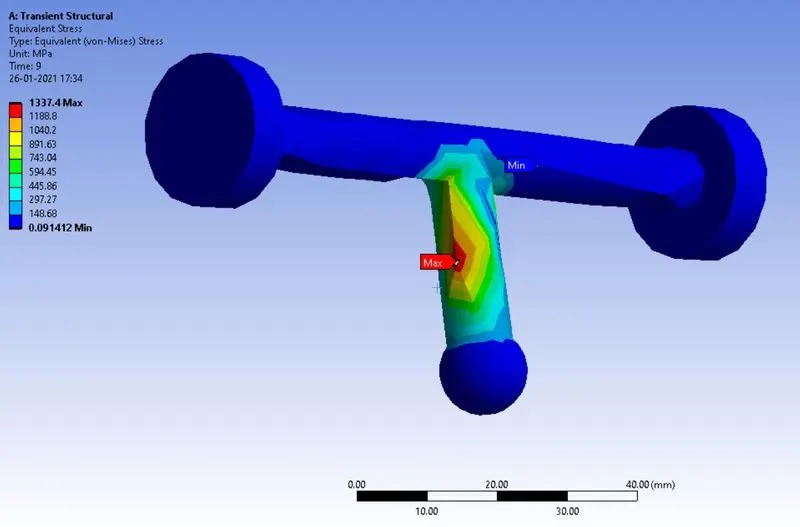
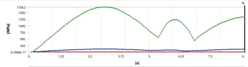
Maximum stress is observed at the cam follower region and the magnitude is 1706.2 MPa. The stress variation with time is plotted below:
The strain contour is given below:
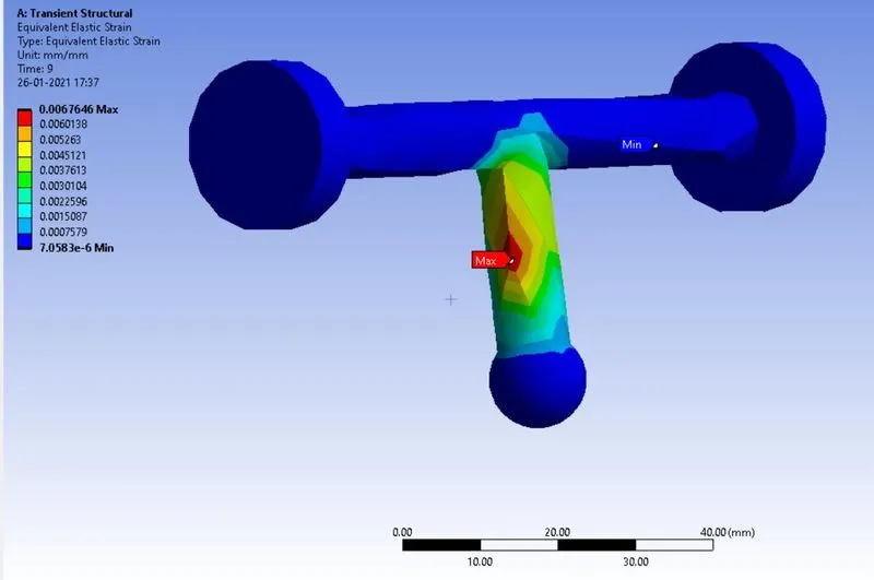
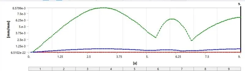
Maximum strain is also seen at the same region where maximum stress was observed, which is intuitive. The maximum strain magnitude is 8.57 e-3. The strain variation with time is plotted below:
CASE 2: Contact type = Frictional, Coefficient = 0.1:
The contact type was changed to frictional, which means that the surface motion has resistance offered. The coefficient of friction was given to be 0.1. The deformation in x-direction is shown below:
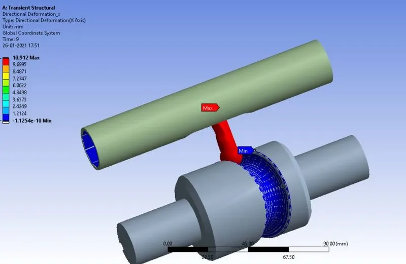
Maximum deformation in x-direction intuitively should not change from the previous case. However, due to frictional resistance, the maximum deformation has increased slightly and is 20.46 mm. Due to resistance in motion when direction is reversed in the cycle, slight increase in maximum deformation is noticed. The stress contour is given below:
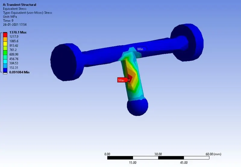
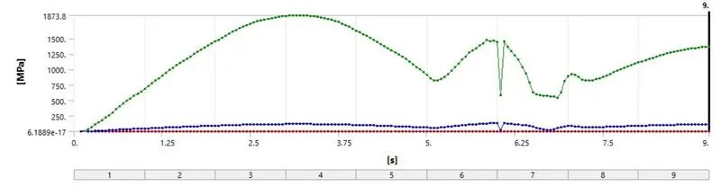
A maximum stress of 1873.8 MPa is observed and its variation with time is plotted below:
The strain contour is shown below:
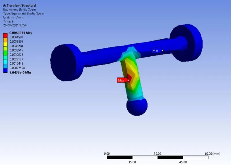
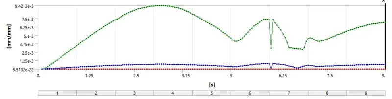
The maximum strain is observed to be 9.421 e-3 and its variation with time is plotted below:
CASE 3: Contact type = Frictional, Coefficient = 0.2:
The coefficient of friction was increased to 0.2. This means that in this simulation the resistance offered to surface motion will be higher than the previous cases. The deformation in x-direction is shown below:
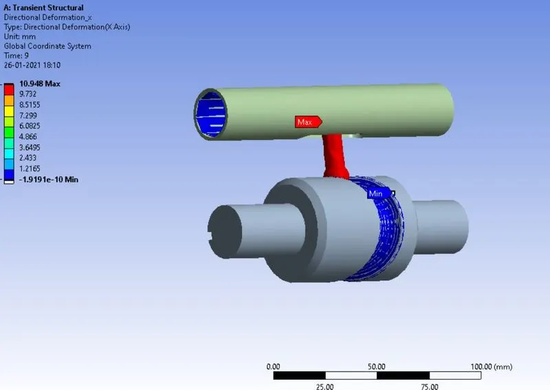
Maximum deformation in x-direction was 20.5 mm. The stress contour is shown below:
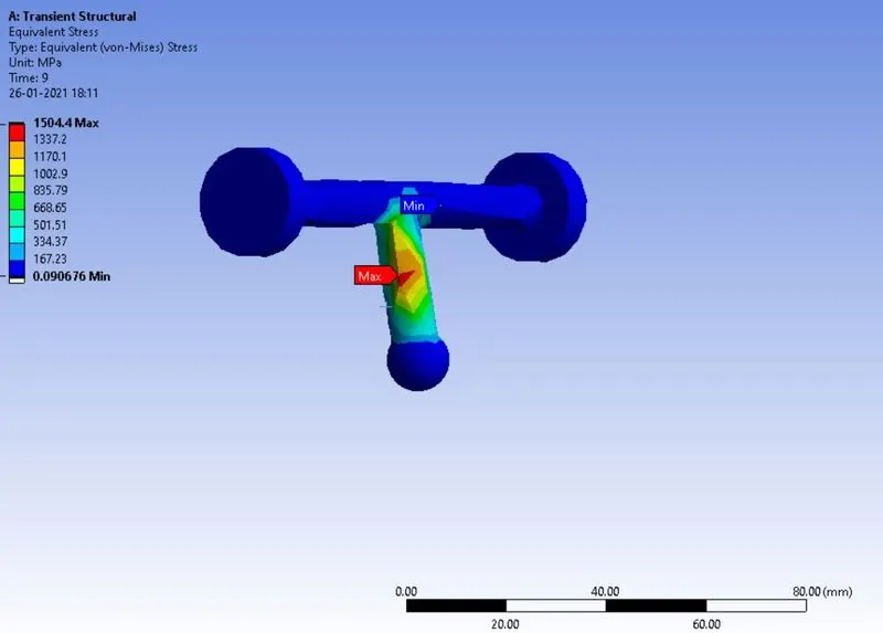
The maximum stress is 2108.3 MPa and variation of stress with time is plotted below:
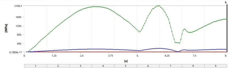
The strain contour is given below:
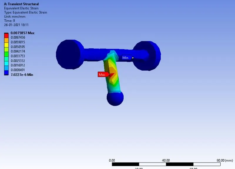
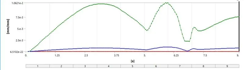
Maximum strain is 1.06 e-2 and its variation with time is plotted below:
The results from the three cases can be summarized by the table below:
|
Cases |
Max deformation in x-axis |
Max Stress |
Max Elastic Strain |
|
Frictionless contact |
20.35 mm |
1706.2 MPa |
8.57 e-3 |
|
Frictional, Coefficient = 0.1 |
20.46 mm |
1873.8 MPa |
9.421 e-3 |
|
Frictional, Coefficient = 0.2 |
20.5 mm |
2108.3 MPa |
1.06 e-2 |
As can be seen from the table, increase in friction leads to increase in maximum deformation of the cam follower. This is because of increased resistance in motion, therefore change in direction takes longer and hence more deformation occurs. This is also visible in stress. Higher resistance to motion leads to higher stress observed in the cam follower. Higher stress intuitively leads to higher strain values. Therefore, to prevent failure of material, frictional resistance has to be lowered. This can be done by either adding tribological materials such as oil, or by smoothening the contact surfaces to lower the frictional coefficient.
CONCLUSION: The transient structural analysis of piston and cam mechanism was successfully completed and the results were quantitatively compared and discussed.