HYPERMESH Project 1 - 2D meshing of interior plastic component of a car door and to assign thickness values
OBJECTIVE: To extract midsurface of the plastic component and mesh it according to the required quality parameters and assign thickness values.
PROCEDURE: In order to successfully mesh the plastic component, the following steps have to be followed:
1. Import geometry into Hypermesh.
2. Perform geometric cleanup.
3. Measure thickness across the component.
4. Extract midsurface manually.
5. Mesh the midsurface and cleanup elements according to given quality parameters.
6. Assign thickness values
STEP 1: Import geometry into Hypermesh:
The given plastic component was imported into Hypermesh. The CAD image of the component is given below:
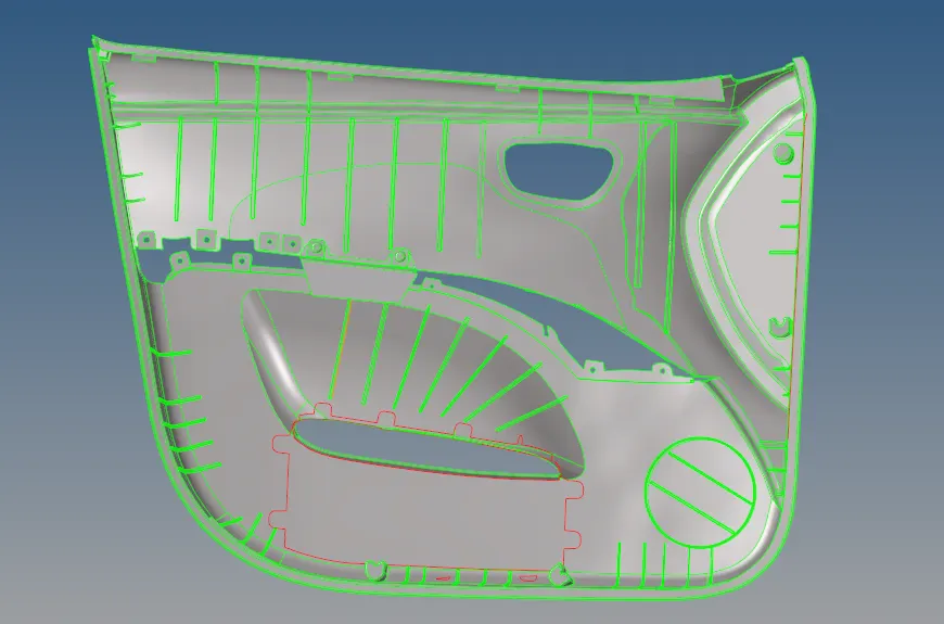
Fig.1 CAD model of the plastic component
STEP 2: Perform geometric cleanup:
In order to obtain a good midsurface with good mesh, the main geometry has to be cleaned first. This can be done by removing fillets at ribs and removing unnecessary areas which can hinder good mesh quality. The fillets can be removed by going to GEOM => defeature => surf fillets. An example of fillet removal is given below.
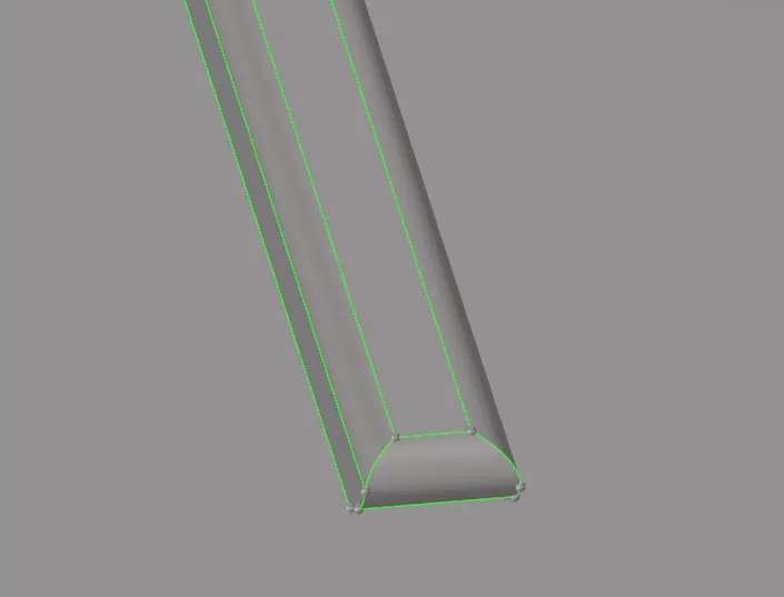
Fig.2 Fillets at the ribs

Fig.3 Defeature tool

Fig.4 Surface fillet removal option
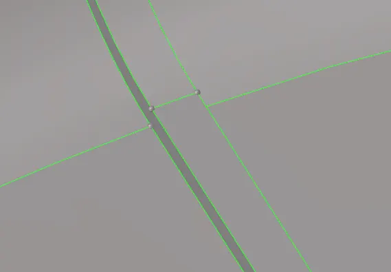
Fig.5 Defeatured fillet
This removal of the fillet results in an easier method of extracting the midsurface of these rib areas.
STEP 3: Measure thickness across the component:
In complex plastic components, extracting midsurface automatically is not possible because thickness is not consistent and varies with region. This means that the midsurface has to be extracted manually. This can be done using offset of the surfaces. But for this method to be implemented, the thickness of these surfaces has to be determined manually. This can be done sometimes easily at the corners by selecting the two points and pressing F4 and selecting the two points. In other cases where surface is not at the corners, other methods have to be used. One convenient method is to create a node on the top surface, and to project that node onto the bottom surface. Then the distance between the two nodes is the thickness value at that region. An example for this is shown below.

Fig.6 Project tool

Fig.7 Projection of nodes onto surface
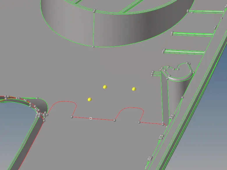
Fig.8 Nodes on top surface
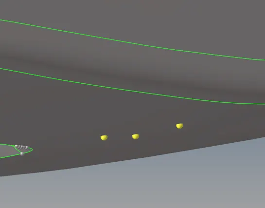
Fig.9 Nodes projected to bottom surface

Fig.10 Calculation of distance between nodes
As can be seen, the thickness in this particular case was found to be 2.8 mm. Similarly, thickness values at all varying regions was determined before extracting the midsurface manually.
Step 4: Extract midsurface manually:
From step 3, the thicknesses were measured. These can be used to extract the midsurface using the surface offset tool which is found at GEOM => surface edit => offset. Give the value of offset to be half of the thickness value.

Fig.11 Surface edit tool

Fig.12 Offset tool for surfaces
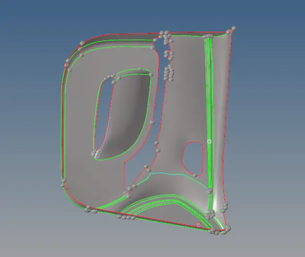
Fig,13 Midsurface without all the features
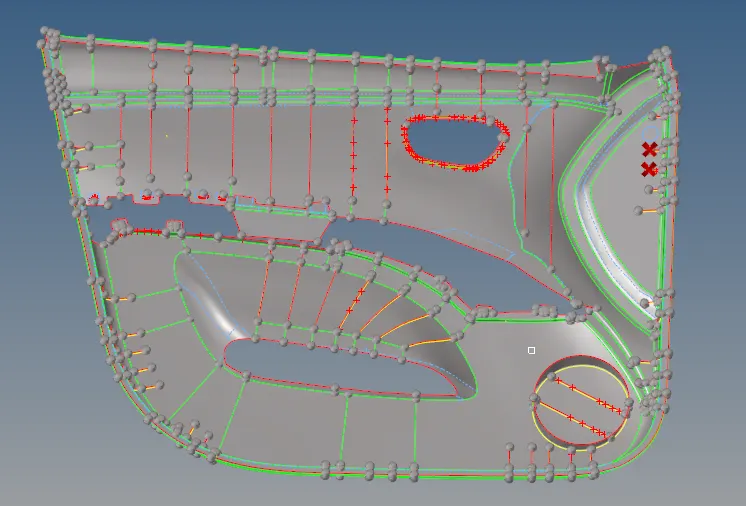
Fig.14 Final midsurface containing all the features
Initially, the main frame of the component was extracted followed by other features which had to be extracted one by one. The interfering surfaces were trimmed and removed. Other surfaces were connected properly using surface extend tool. For some features with uneven thickness, offset cannot be used to extract midsurface. In these cases, a midline of one surface was drawn and this midsurface was used to trim the top and bottom surfaces. The two midlines at top and bottom were now used to create a new surface which would be perfectly at the middle. One example of this is given below:
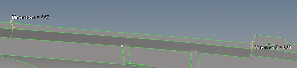
Fig.15 Non-uniform thickness

Fig.16 Lines tool

Fig.17 Mid line tool
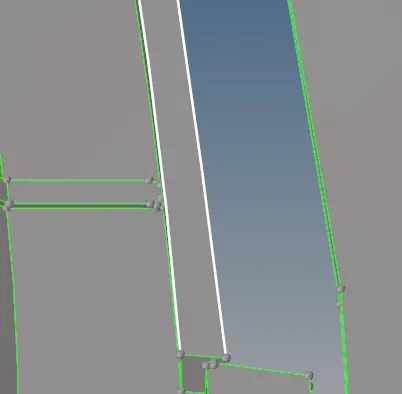
Fig.18 Lines selected to create mid line
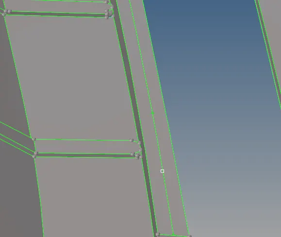
Fig.19 Midline created
Using this method and the offset method, the final mid surface was successfully extracted.
Step 5: Mesh the midsurface and cleanup elements according to given quality parameters
Meshing of the midsurface is done using 2D => Automesh option. A proper mesh flow has to be ensured and this can be done by meshing surface and then meshing the adjacent surfaces. One by one the surfaces are meshed and the mesh of the whole surface is obtained. This mesh now has to follow the quality parameters which can be inserted into Hypermesh at Preferences => Criteria File Settings.
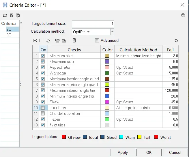
Fig.20 Mesh quality criteria
The tools used for quality control of the elements are found at 2D => quality index => cleanup tools. The cleanup tools available in Hypermesh are given in the figure below:

Fig.21 Clean up tools
After cleaning up elements that are failing for quality criteria such as warpage, minimum size, maximum size, etc, it is also important to adjust elements for other things. Below images show elements which were adjusted for trias touching each other, opposite trias, high tria concentration regions, and disconnected elements.
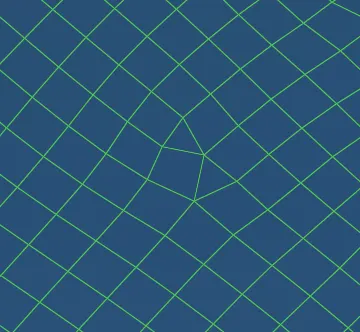
Fig.21 Trias touching each other
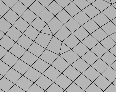
Fig.22 Trias dragged away
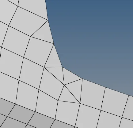
Fig.23 High trias concentration
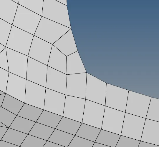
Fig.24 Remeshed region containing rotational quads
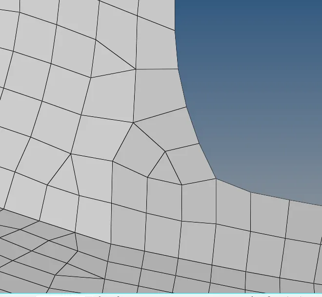
Fig.25 Remeshed region to remove rotational quads
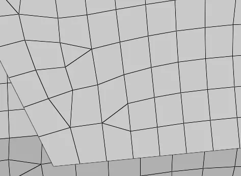
Fig.26 Opposite trias
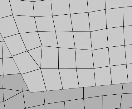
Fig.27 Opposite trias removed
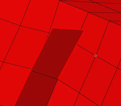
Fig.28 Bad connection between elements
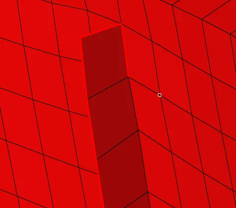
Fig.29 Connection issue resolved
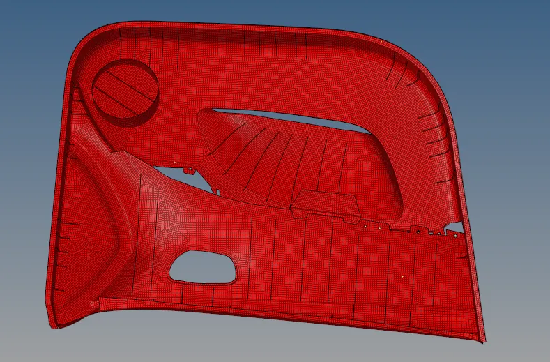
Fig.30 Final mesh of the plastic component midsurface
Step 6: Assign thickness values:
To assign thickness values, we have to create properties and assign respective thicknesses. This is followed by creating a component and assigning the respective property. Then the meshes are assigned to their corresponding component values by using the tool Tool => organize => collectors.
An example of the list of components and properties that were created for the purpose of this project are given below:
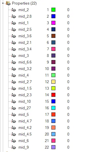
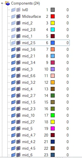
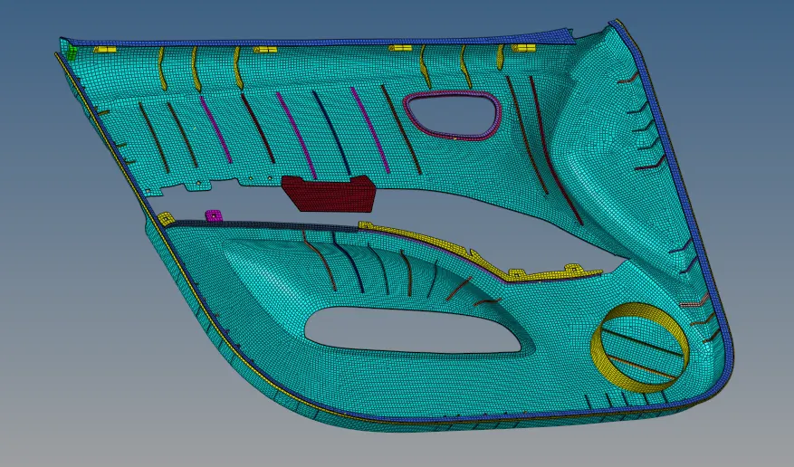
Fig.31 Final mesh after assigning thicknesses
Thus, the plastic component meshing is completed.
CONCLUSION: The midsurface of the plastic component was successfully extracted by utilizing manual methods. The midsurface was then successfully meshed and the elements were cleaned up to follow the quality parameters. Thickness values were assigned to the elements corresponding to their respective values as given in the CAD geometry.
Link to final mesh:- https://drive.google.com/file/d/1QrKVLrNoUoJoHfjzDDLpCwIvmg0aZUfn/view?usp=sharing