3D Tetra meshing of various components using HYPERMESH
OBJECTIVES: To perform 3D meshing of given models and to check for given quality parameters such as element size and tet collapse values.
PROCEDURE:
To ensure good quality of 3D mesh of the given models, the following steps have to be taken:
1. Import geometry into Hypermesh
3. Perform 3D meshing on the components
4. Ensure that no element fails for tet collapse
In total, three main models had to be meshed for the purpose of this assignment. The CAD models of the models are given below.
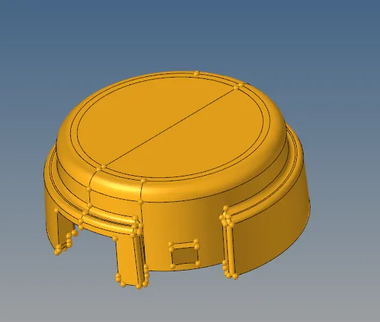
Fig.1 CAD model of housing
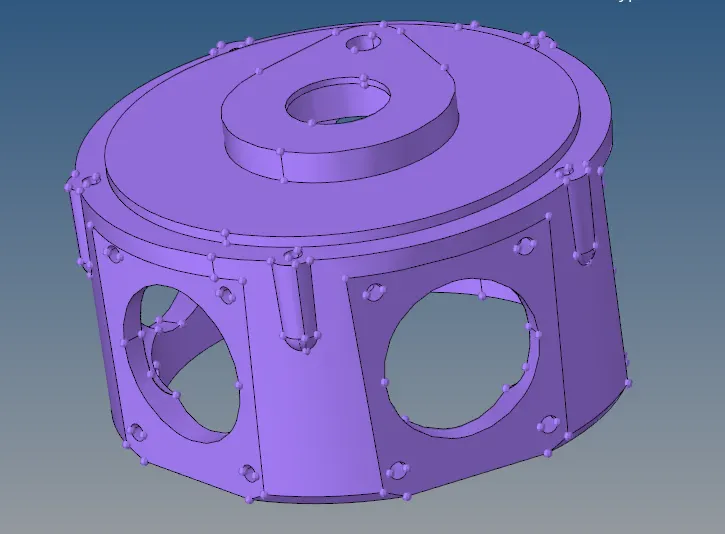
Fig.2 CAD model of 2nd model
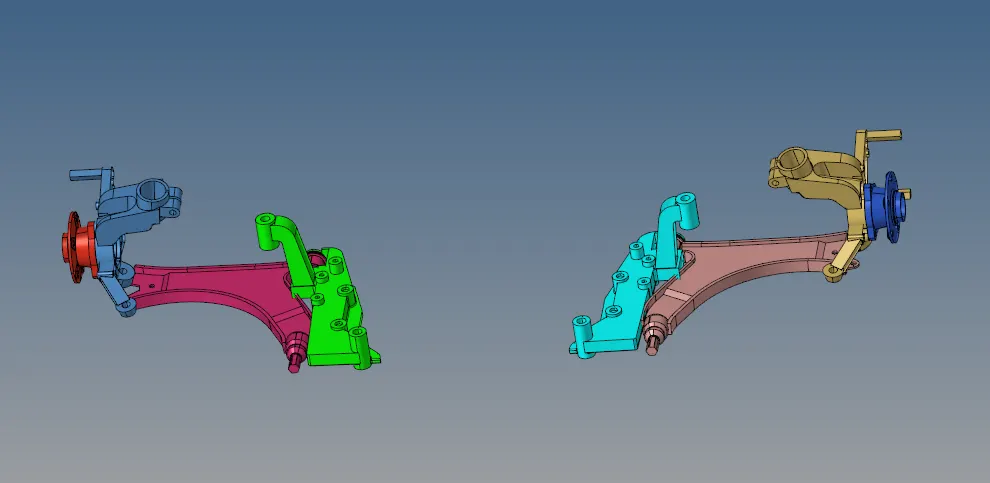
Fig.3 CAD model of the 3rd model
3D meshing can be performed using different methods in Hypermesh. Each method has its own advantage and disadvantage. The following methods can be used to perform 3D printing:
1. Mesh with 2D tria elements followed by Tetrameshing.
2. Quick tetra method
3. Volume tetra method
In this report, all three methods are performed and documented. The first model was meshed using the first method mentioned above i.e meshing initially with 2D tria elements followed by tetrameshing. The procedure to carry this out is to initially perform 2D shell meshing by going to 2D => automesh and selecting trias as element type.

Fig.4 Automesh option

Fig.5 Mesh settings
Using this option, the two components of the housing model were meshed with 2D shells.
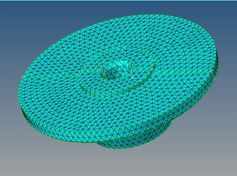
Fig. 6 2D Meshing of the interior component of the housing model
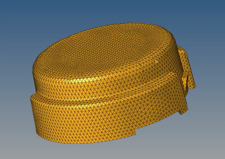
Fig.7 2D meshing of the exterior component of housing model
After 2D meshing is completed and element sizes are checked for quality parameters, we can proceed to 3D meshing using Tetra mesh method. This can be achieved by going to 3D => Tetra mesh => Tetra mesh. The 2D elements are selected and meshed to perform the required 3D mesh.

Fig.8 Tetramesh option

Fig.9 Tetramesh settings
The 3D mesh is hence completed and can be seen below:

Fig.10 3D elements seen within the housing component
However, we should also assure that no element fails for tet collapse. Tet collapse value was given to be 0.15 which means that each elements should have tet collapse value of over 0.15 in order to qualify for quality criteria. This can be done by pressing F10 or Tools => check elems which takes us to elements checking tool. Here, enter value of 0.15 on tet collapse and click on tet collapse. At the bottom right corner Hypermesh will show the amount of elements that have failed for the tet collapse. If any element is failing, it needs to be corrected. However, in case of the housing model, no element was failing for tet collapse. Hence, the model was successfully meshed for tetra mesh.
The second method which is quick tetra was used to mesh the second model given in figure 2 above. The way to achieve quick tetra is to go to the toolbar at the top of the panel and go to View => Browsers => Hypermesh => Utility and ensure that Utility option is ticked. This opens the Utility menu on the right side of Hypermesh GUI. Select Geom / Mesh on it followed by Quick tetramesh option. This opens up the Quick tetramesh tool using which quick tetra can be performed.
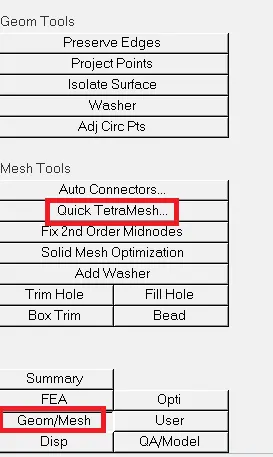
Fig.11 Utility tool
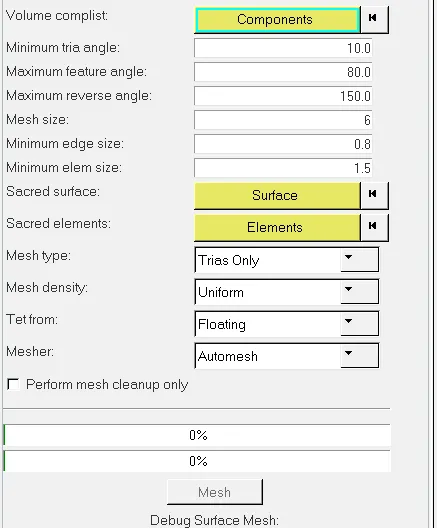
Fig.12 Quick tetramesh tool
By selecting the appropriate options and the components to mesh, the 3D tetra mesh can be completed. Model 2 after meshing looks like this:
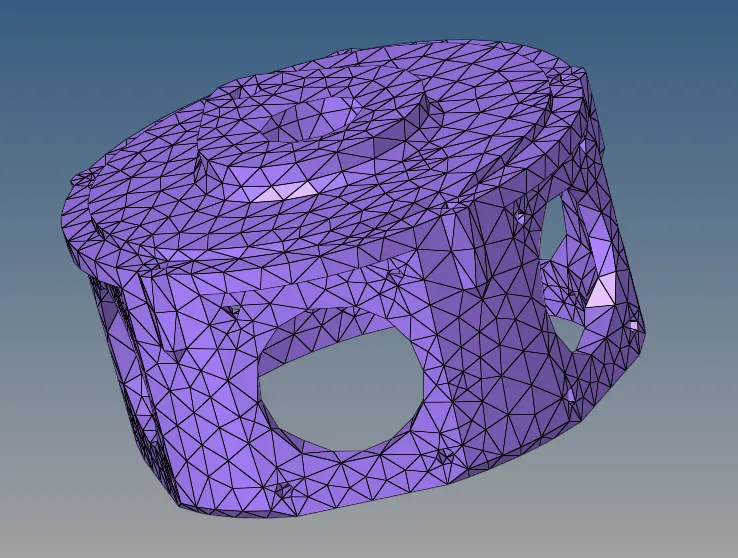
Fig.13 Quick tetra mesh of model 2
This model has to be checked for tet collapse similar to previous model. In this case, several elements are failing for tet collapse. These elements can be saved and using the mask option they can be separated from rest of the elements. These elements that are failing for tet collapse can be corrected either by using remeshing or by manually translating the nodes. To use remesh option, we can go to 3D => tetramesh => Tetramesh parameters where the tet collapse value of 0.15 can be entered. Then remesh is done by going to 3D => tetramesh => Tetra remesh.

Fig.14 Element checking tool
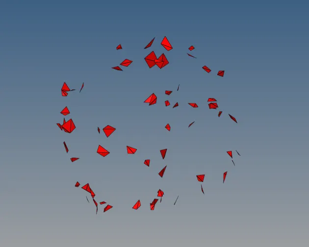
Fig.15 Elements failing for tet collapse

Fig.16 Tetramesh parameter settings

Fig.17 Tetra remesh settings
This solves some of the elements but some will still be failing for tet collapse and have to be manually adjusted. This can be done by going to Tools => Translate and by picking the appropriate nodes on each element, the tet collapse value can be adjusted.

Fig.18 Translate tool

Fig.19 Translate tool settings
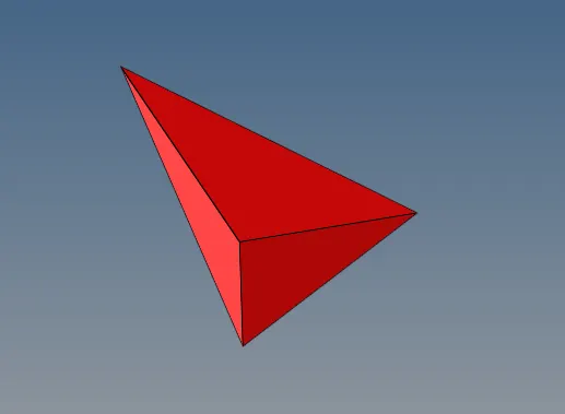
Fig.20 Element failing for tet collapse
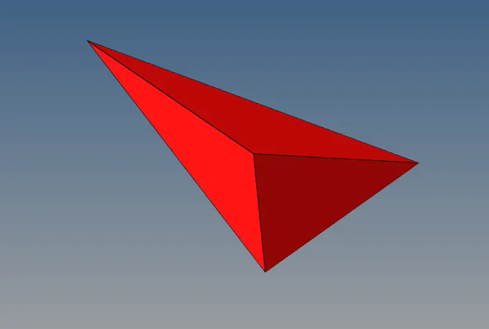
Fig.21 Element after adjusting for tet collapse.
In this manner, the elements can be adjusted to not fail for tet collapse.
The third model was meshed using volume tetra method. This can be done by going to 3D => Tetramesh => volume tetra. This will result in tetra mesh formation on the solids. Similar to the other models, it must be inspected for failure of tet collapse. Similar methodology of remeshing followed by manual adjustment of elements was done in this case and the final mesh was achieved successfully which does not violate the given quality criteria.

Fig.22 Tetramesh option

Fig.23 Volume tetra settings

Fig.24 3D elements within the component
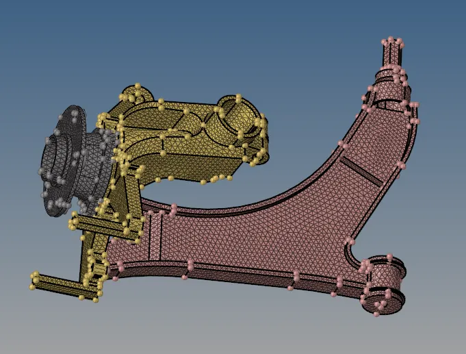
Fig.25 Final mesh of the third model
CONCLUSION: The three models given were meshed with 3D tetra elements as per the quality parameters indicated by the assignment successfully. All three possible methods of tetra meshing were demonstrated and quality checking approaches were documented.