Structural Analysis of Railwheel and Track using ANSYS Workbench
AIM: To perform structural analysis on a railwheel and track setup using ANSYS Workbench.
PROCEDURE:
Initially the model consisting of the railwheel and track setup was imported into ANSYS and the geometry is shown below:
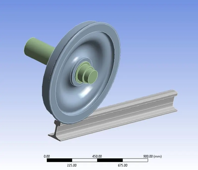
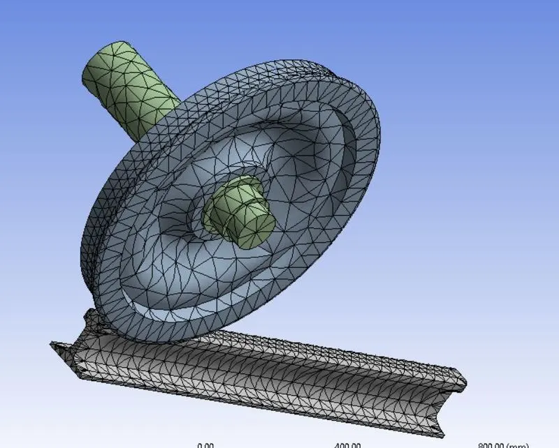
A mesh of size 50 mm with face sizing of 35 mm element length at faces which will come in contact was given. The mesh is shown below:
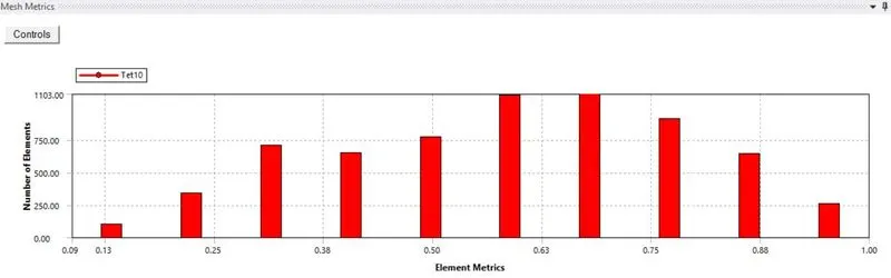
The mesh element size distribution is given below in the histogram:
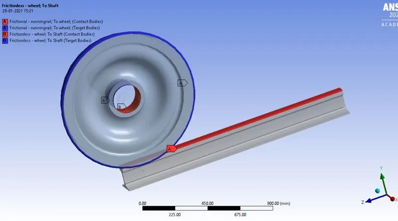
The bearing contact was given as frictionless and the contact between the wheel and the railtrack was given as frictional contact as shown below:
The track was given fixed support as given below:
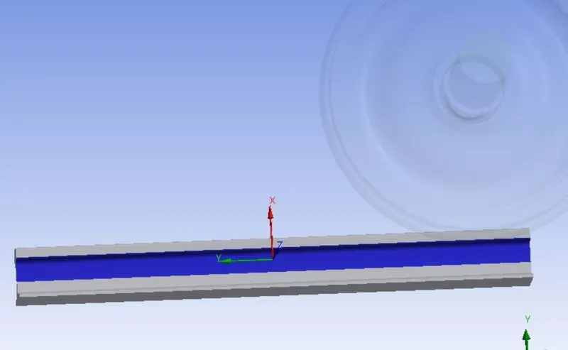
The wheel was given planar joint as shown below:
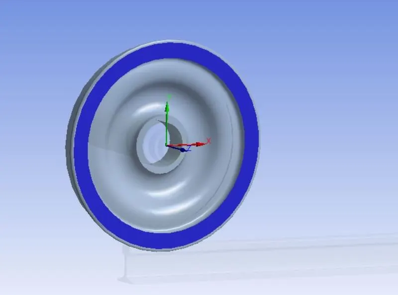
The shaft was given a translational joint with x-axis being the directional of translation of the wheel on the track as shown below:
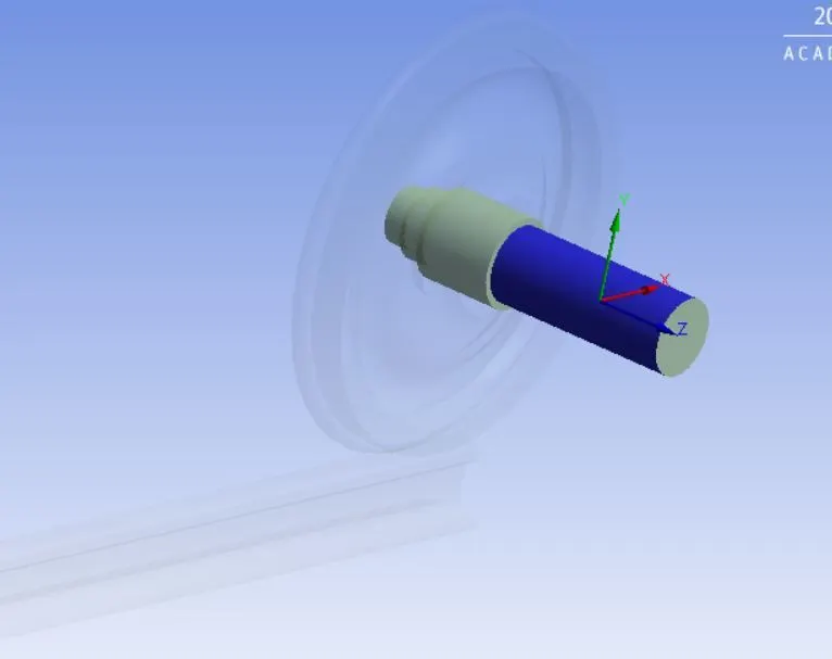
The bearing was given a load of 100000 N as shown below:
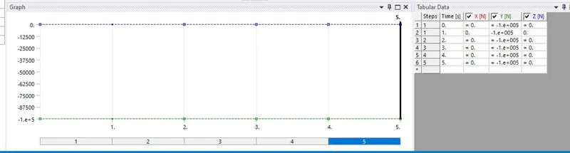
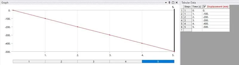
The translational joint given to the shaft was given a displacement of 500 mm as shown below:
The simulation was solved for 5 steps of displacement and the resulting stress contour is given below:
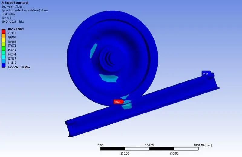
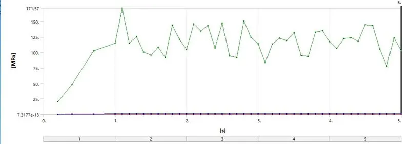
A maximum stress of 171.57 MPa was observed and the variation with time is plotted below:
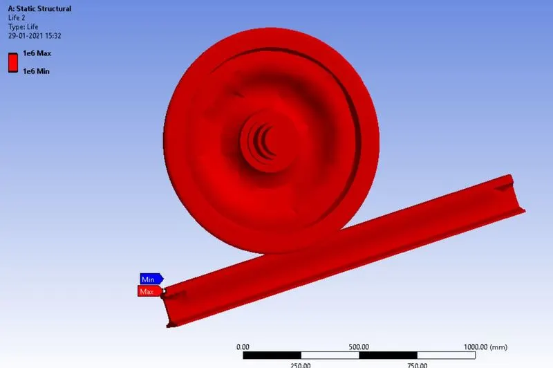
The stress life was calculated and life of 1e+6 was observed as shown in the contour plot below:
The total deformation contour is shown below:
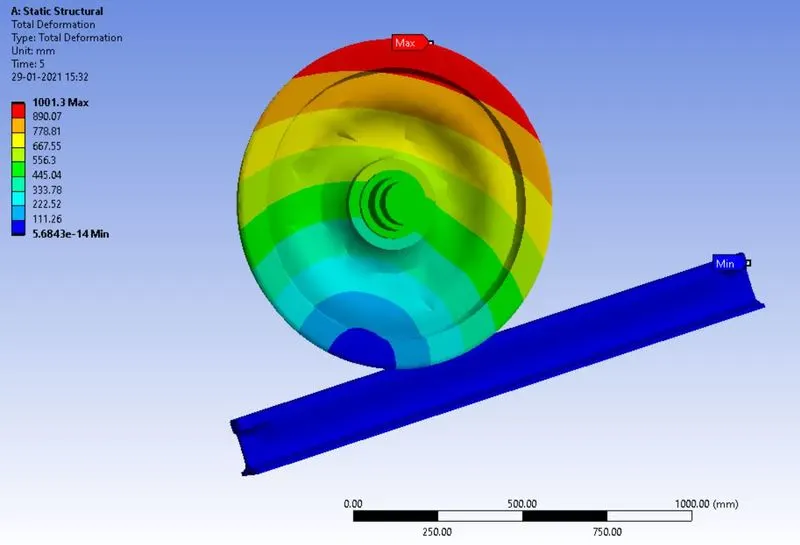
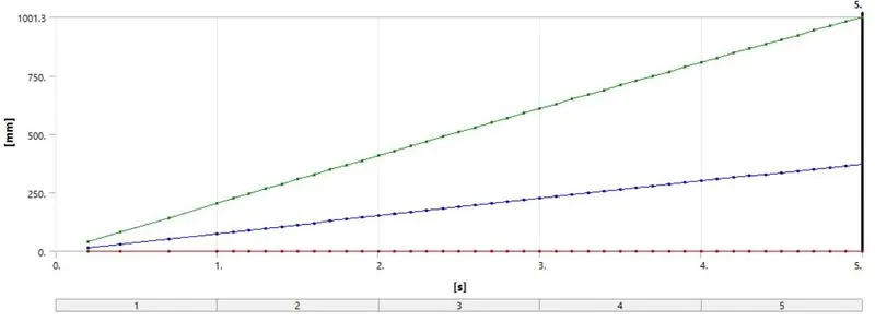
The maximum deformation was observed to be 1001.3 mm and its variation with time is shown below:
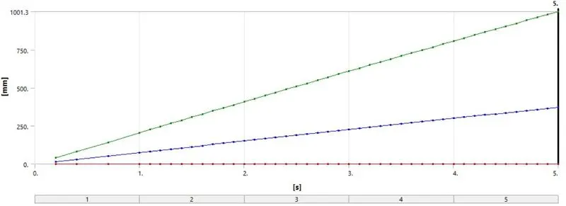
The displacement varies linearly with time. This program defined displacement was compared to a user-defined displacement function. The user-defined displacement is shown below:
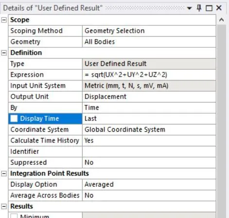
User-defined expression is `U = sqrt [Ux^2+Uy^2+Uz^2]`
The resulting deformation contour of user-definition is shown below:
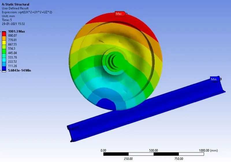
The user-defined displacement also has a maximum of 1001.3 mm and is also a linear variation with time as shown in the plot below:
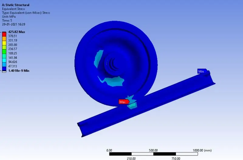
The bearing load is now increased from 100000 N to 500000 N and the simulation is solved with the rest of the parameters kept constant. The stress contour is shown below:
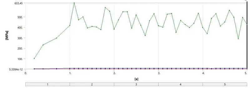
Maximum stress of 633.45 MPa was observed and the variation with time is plotted below:
The life of the track is shown below:
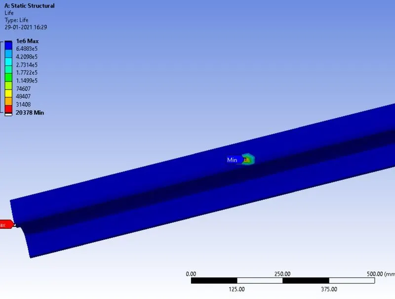
The life of the track in contact with the wheel is 20378 and the deformation contour is given below:
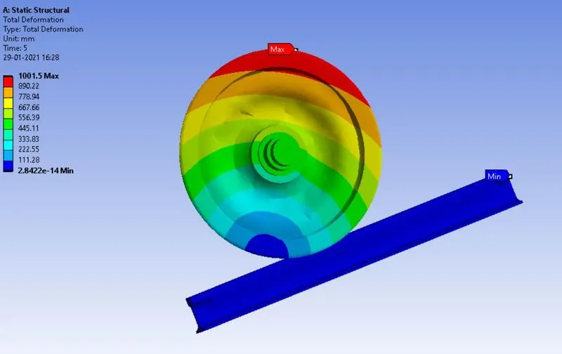
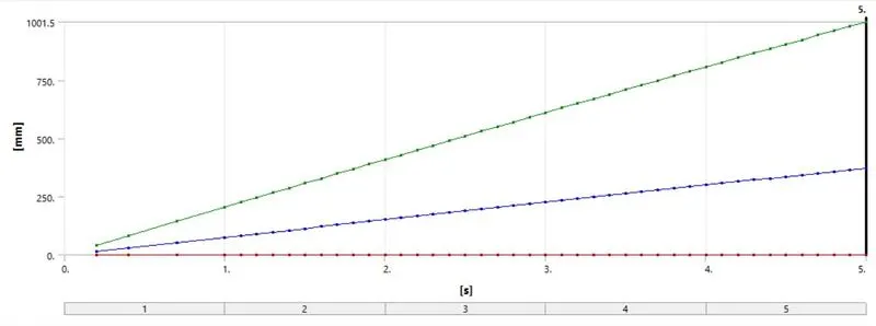
The maximum deformation of the wheel is 1001.5 mm and its variation with time is linear variation with time and is plotted below:
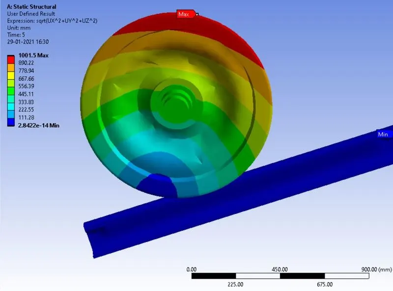
The user-defined deformation contour results are shown below:
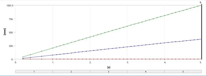
The maximum deformation observed is 1001.5 mm and its variation with time is plotted below:
The results from the two bearing load cases can be summarized by the table below:
|
Bearing Load |
Max Deformation |
Max Stress |
Life |
Max User-Defined Deformation |
|
1 e+5 N |
1001.3 mm |
171.57 MPa |
1e+6 |
1001.3 mm |
|
5 e+5 N |
1001.5 mm |
633.45 MPa |
20378 |
1001.5 mm |
The maximum deformation when bearing load increases is 0.2 mm difference which is not statistically significant. However, the life of the rail track decreases significantly from 1e+6 to 20378. The maximum stress also increases significantly from 171.57 MPa to 633.45 MPa. The user-defined deformation result is exactly matching the deformation result obtained from the software. This indicates that the user-defined criteria was deformation was accurately defined.
CONCLUSION: The structural analysis of the railwheel and track setup was successfully performed and the results were compared quantitatively.