HYPERMESH Project 2 - 2D meshing of sheet metal panel used for storing spare car tyre
OBJECTIVE: To extract midsurface of the sheet metal component and to perform 2D meshing on the midsurface according to the given quality criteria.
PROCEDURE: In order to successfully mesh the given component, the following steps have to be followed:
1. Import geometry into Hypermesh
2. Extract mid-surface of the component
3. Perform geometric cleanup of midsurface
4. Apply 2D mesh on the midsurface
5. Clean up the elements to adhere to the quality criteria
STEP 1: Import geometry into Hypermesh
The geometry was imported into Hypermesh and the CAD design of the sheet metal panel can be seen below:
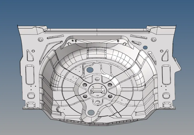
Fig.1 CAD geometry of the sheet metal panel
STEP 2: Extract mid-surface of the component
The midsurface was initially extracted automatically using GEOM => midsurface => auto extraction. The extraction option of offsets + planes + sweeps was selected to get the best result.

Fig.2 Midsurface tool

Fig.3 Extraction options
The midsurface was extracted as is shown in the figure below:
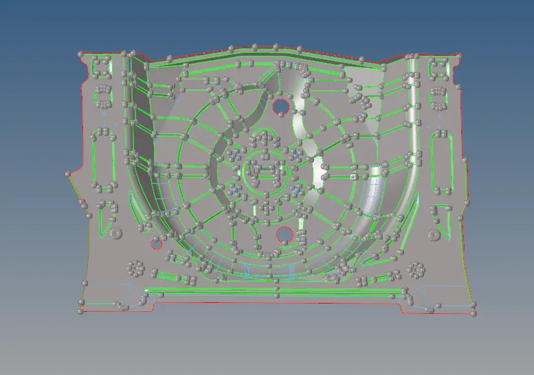
Fig.4 Midsurface of the panel
However, some of the midsurface was not captured properly and had to be extracted manually as is shown in the figures below. To extract from parent geometry, use the offset tool by going to GEOM => surface edit => offset. Offset the surface from parent geometry into midsurface and then join to the surrounding surfaces using the well known quick edit tools.
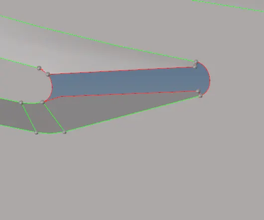
Fig.5 Incomplete midsurface
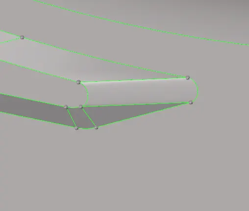
Fig.6 Parent geometry

Fig.7 Surface edit option

Fig.8 Surface offset tool
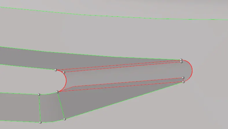
Fig.9 Surface offset to midsurface
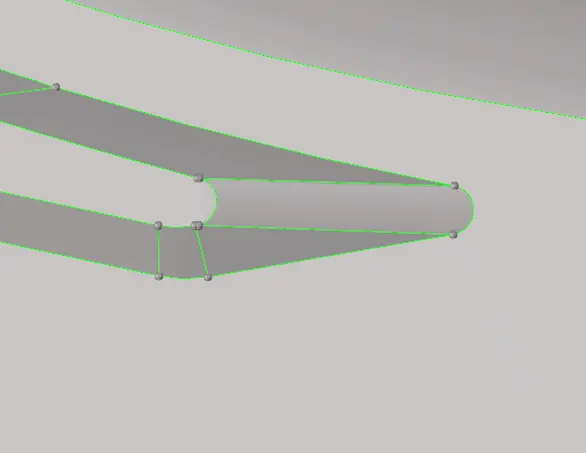
Fig.10 Offset surface stitched to surroundings
STEP 3: Perform geometric cleanup of midsurface
After midsurface is extracted completely, the cleanup has to be performed which is primarily done using quick edit tools.

Fig.11 Quick edit option

Fig.12 Tools present in quick edit panel
Some surface lines will lead to poor mesh flow or will fail for minimum element length. These lines have to be suppressed using toggle edge.
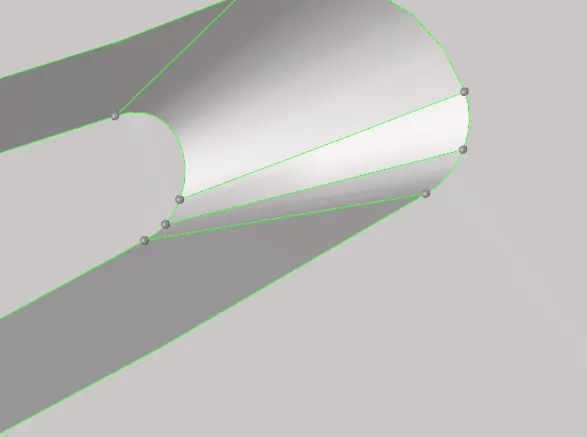
Fig.13 Surface before suppressed edges
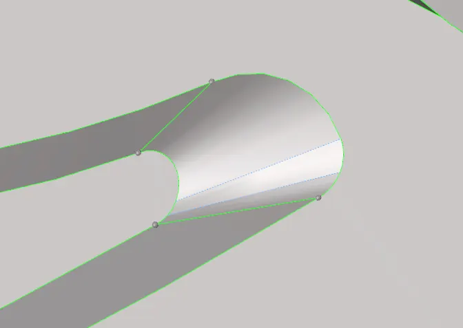
Fig.14 Surface after the suppression of edges
Some surfaces have overlapped one another and these need to be improved to have the proper shape. One example of this is shown below:
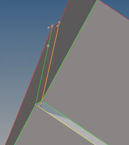
Fig.15 Improper surface
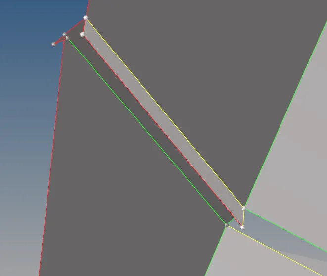
Fig.16 Surfaces are trimmed at intersection
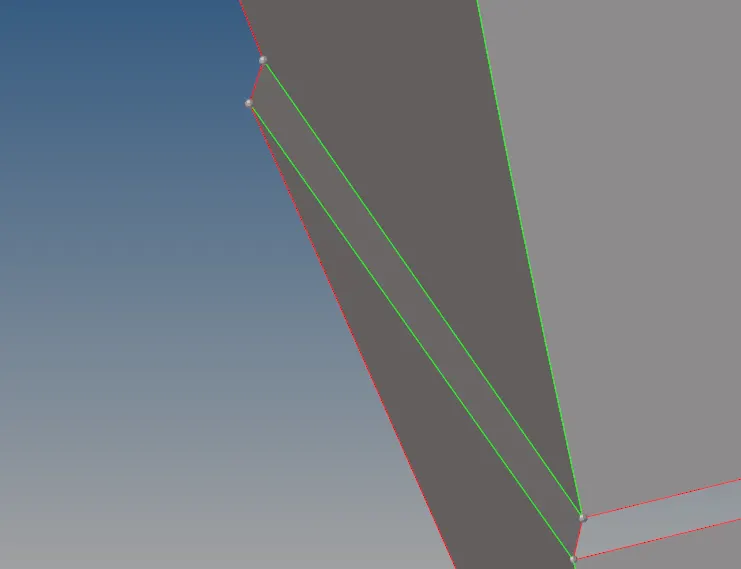
Fig.17 Excess surfaces are removed
In some cases, free edges are formed due to various reasons and these can be stitched together by toggling edges and replacing a few points.
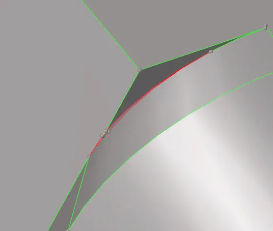
Fig.18 Free edges
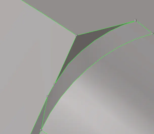
Fig.19 Free edges stitched together
In this manner the midsurface is cleaned up and is ready for meshing operation.
STEP 4: Apply 2D mesh on the midsurface
The midsurface is meshed with 2D elements with one surface meshed followed by its surrounding surfaces being meshed. This is done to ensure a proper mesh flow is obtained.
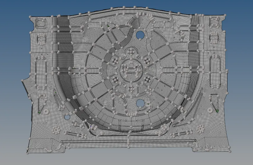
Fig.20 Initial mesh
STEP 5: Clean up the elements to adhere to the quality criteria
The mesh now has to be cleaned up according to the required quality criteria which is given below:
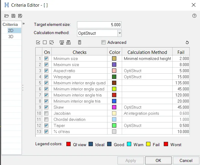
Fig.21 Quality criteria parameters
Apart from the parameters, certain other features such as opposite trias, trias touching each other , etc have to also be removed.
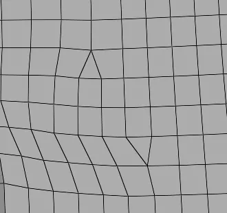
Fig.22 Opposite trias
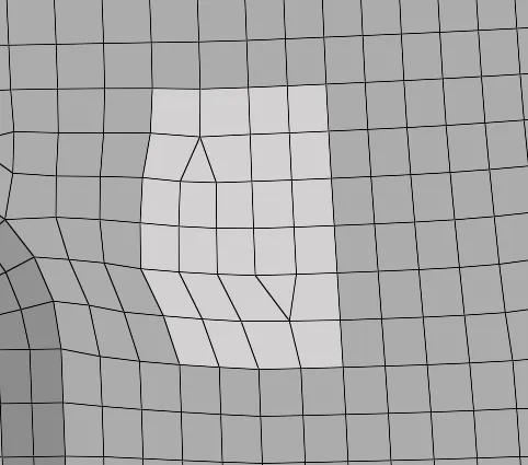
Fig.23 Region selected for remesh
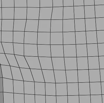
Fig.24 Remeshed surface with opposite trias removed
The opposite trias were removed by selecting the appropriate parts and remeshing for quad elements.
Another example of cleaning elements is given below where a sudden change in terrain has led to many elements failing for maximum element length and warpage. For maximum element length, the distance tool was used and distance (GEOM => distance)between the nodes was adjusted according to the given parameters. For warpage, the translate tool (Tool => translate)was used.
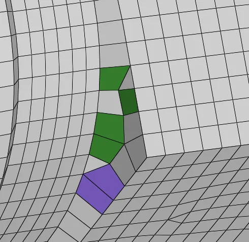
Fig.25 Area with multiple failed elements. Purple is for maximum element length failure and green is for warpage failure.

Fig.26 Distance tool

Fig.27 Distance tool being used to adjust the element lengths
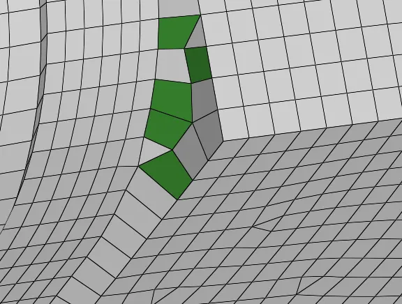
Fig.28 Only warpage failure is remaining

Fig.29 Translate tool
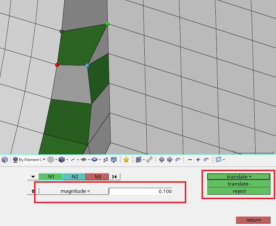
Fig.30 Translate tool being used to remove warpage failure
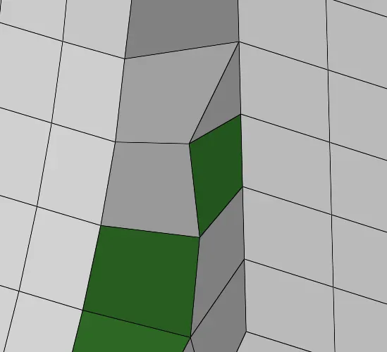
Fig.31 Warpage failure is removed from the element
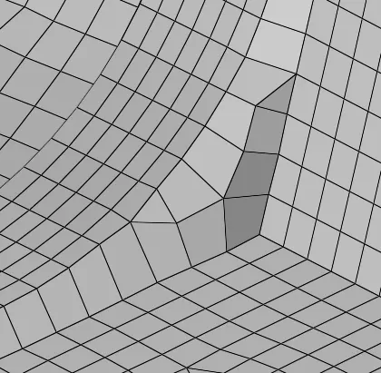
Fig.32 All failures are eliminated from the region
In this manner, the failures from the complete mesh was removed and tria elements were eliminated as much as possible. The final mesh is shown below:
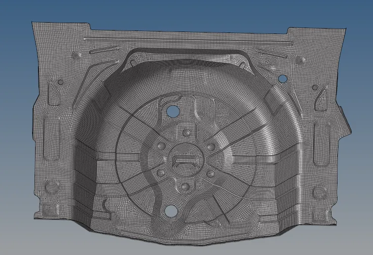
Fig.33 Final Mesh
CONCLUSION: The midsurface of the sheet metal panel was extracted successfully followed by geometric cleanup of the midsurface. 2D mesh was applied to the midsurface and the elements were cleaned up successfully to adhere to the quality criteria standards.