Meshing of hood using HYPERMESH
OBJECTIVE: To extract midsurface from the CAD model of a hood and to perform geometric clean-up. The midsurface is then to be meshed to the necessary quality criteria.
PROCEDURE:
In order to completely mesh the hood, the following steps have to be completed:
1. Import the geometry into Hypermesh
2. Extract the midsurface of the hood parts
3. Perform geometric cleanup on the midsurfaces
4. Mesh the hood parts
5. Clean up the elements to satisfy the quality criteria
STEP 1: Import the geometry
Initially, the CAD model of the hood is imported into Hypermesh. The CAD model is differentiated into five parts namely outer hood, inner hood, two hinges and one latch. The CAD models of the outer hood and inner hood are given below.
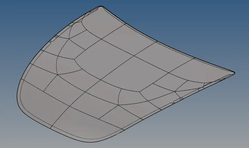
Fig.1 CAD model of the outer hood
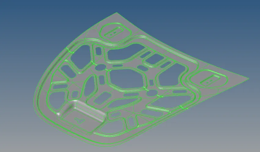
Fig.2 CAD model of the inner hood
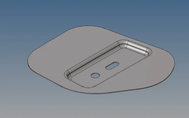
Fig.3 CAD model of the hinge
STEP 2: Extracting midsurface
Following the importing of the CAD models, the midsurface of the five parts are extracted using GEOM=>midsurface=>auto midsurface. The skin offset method was used in the extraction options. Following extraction of midsurface, quality criteria were added to the algorithm using Preferences => Criteria File Settings.
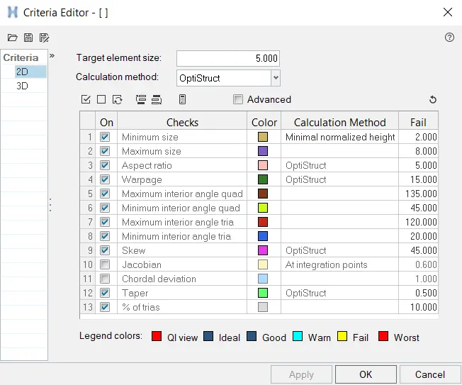
Fig.4 Quality criteria for mesh
STEP 3: Geometric cleanup of midsurface
The midsurfaces were geometrically cleaned using GEOM => quick edit.
The following tools are useful for performing geometric cleanup in this case:
1. Toggle Edge: This tool can be used to toggle and change the type of edge. There are several kinds of edges seen in Hypermesh. The various kinds of edges present in Hypermesh can be seen in the below diagram.
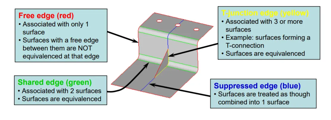
Fig.5 Different edges in Hypermesh (Source :Altair University)
The "Toggle Edge" tool can be used to change one edge to another. This is especially useful to maintain quality criteria of the mesh. This tool is used to suppress shared edges that can cause elements to be of a very low size and which can fail the minimum edge requirements. It can also be used to toggle free edges into shared edges. In some cases, Hypermesh incorrectly creates free edges in places where it should be a shared edge. In this case, toggling a free edge into a shared edge eliminated the problem.
2. Project point: Project point tool is used to project a point from one line to another line.
3. Split surf - node: This tool is used to split a surface using two nodes as reference. This tool is utilized simultaneously with project points in order to prepare grid-like surfaces in order to get proper flow of mesh in certain cases.
4. Split surf - line: This tool is used to split a surface using a node and a line as reference. This tool can be used to circumvent the projection of a point onto a line and then splitting using nodes. Instead the surface is split directly by choosing a node on one line and choosing another line onto which the surface is being split upon.
A combination of the above tools was used to create grid-like surface splits onto the outer part of the hood which can be seen below:
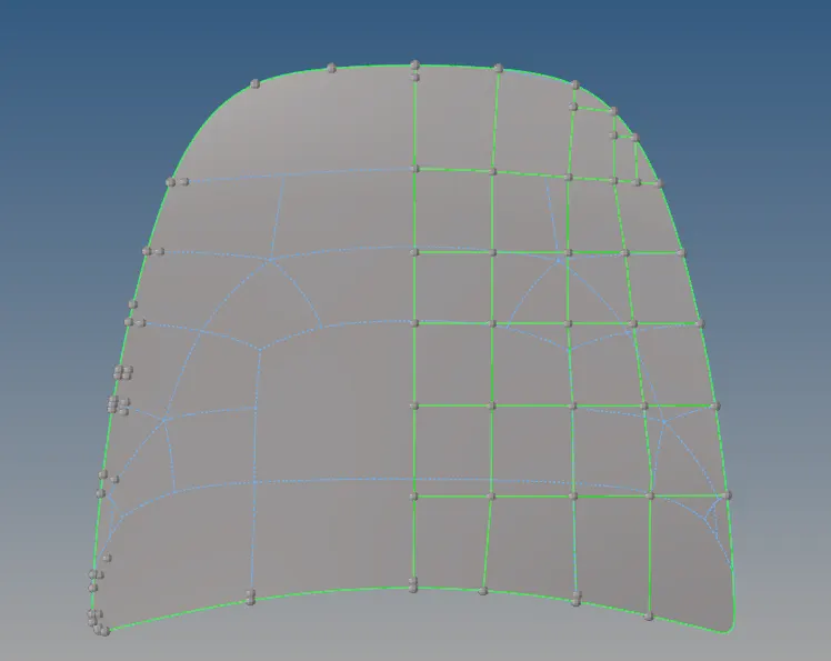
Fig. 6 Grid like surface splits done on outer hood part
The blue lines indicate the shared lines that were originally in the model which were suppressed. The original lines were not ideal to create proper mesh flow with quad elements prominent. In order to dominantly mesh with quads and with proper flow, the surfaces were split into grids onto which meshing can be done easily and with high quality.
Similar geometric cleanup was also done for inner part of the hood where there were areas with very small and protruding surfaces which would easily fail for minimum element length. An example of this is shown below.
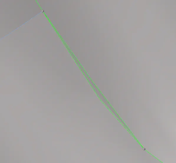
Fig.7 Small surface bound by two shared edges
In Fig.7, the surface that is being bound by the two green edges is clearly too small and will definitely failed the quality criteria for minimum edge size. In order to eliminate this, one of the edges has to be suppressed.
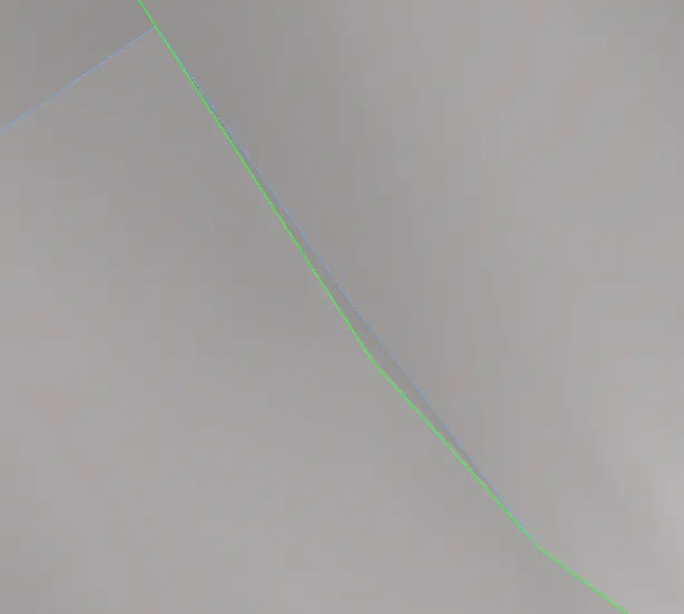
Fig.8 Suppressed edge
Now that the edge is suppressed, the mesh will not fail minimum length criteria. This is just one example. Several lines such as this have to be toggled for the complete geometry to meet the quality requirements. Therefore, geometric cleanup is one of the most important steps to perform.
STEP 4: Mesh the hood parts
Meshing for midsurfaces such as hood parts is done using 2D elements with predominantly quad-elements. Tri elements cannot be removed completely but need to be avoided as much as possible. This can be done by clean up tools which will be discussed further in step 5. The hinge part was meshed first. Meshing is done automatically by selecting surfaces using 2D => Automesh option. Element size of 5 units was selected and depending upon surface geometry, either mixed elements or quad elements can be selected.
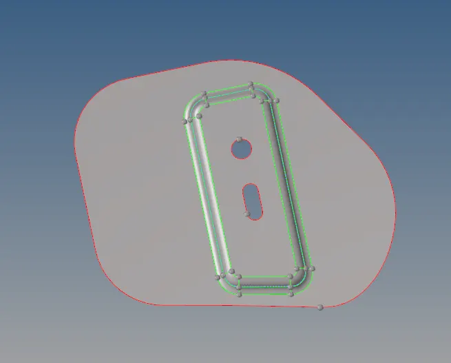
Fig. 9 Hinge of the hood prior to meshing
Surfaces were meshed one-by-one to maintain quality. In some cases, tri elements showed up which were easily eliminated by changing the number of nodes.
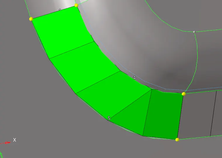
Fig. 10a) Tri-elements show up during meshing
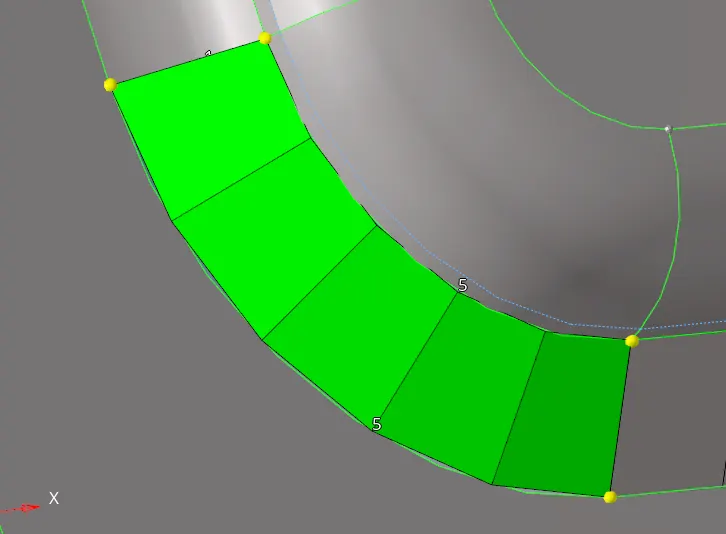
Fig. 10b) Tri-elements removed
In some cases, the geometry was not properly meshed completely. In these cases, the mesh was improved by increasing number of nodes in order to capture the feature completely.
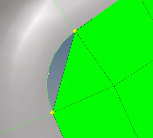
Fig. 11a) Improper capturing of features
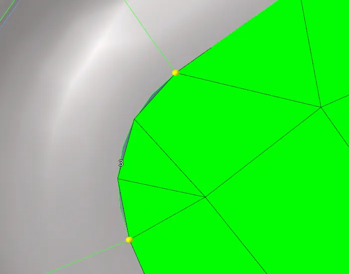
Fig. 11b) Feature capture improved by increasing nodes
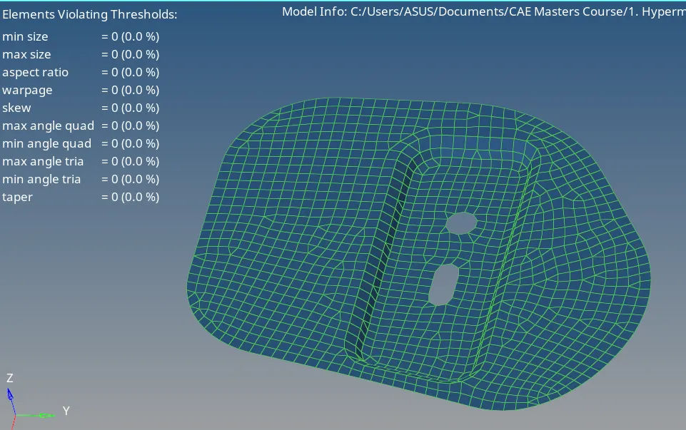
Fig.12 Meshing of the hinge
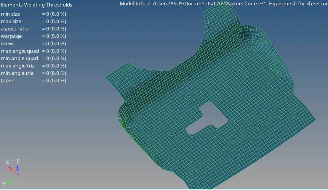
Fig.13 Mesh of the latch
The outer and inner parts of the hood are similarly meshed. The meshed parts are shown below.
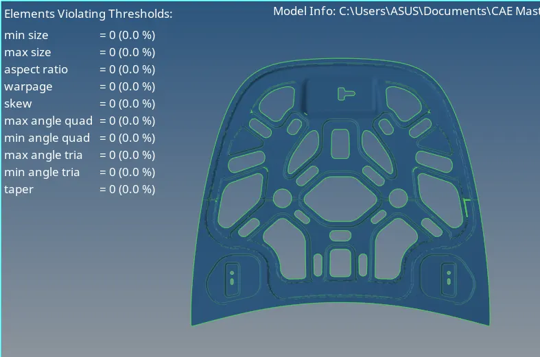
Fig.14 Meshed inner hood part
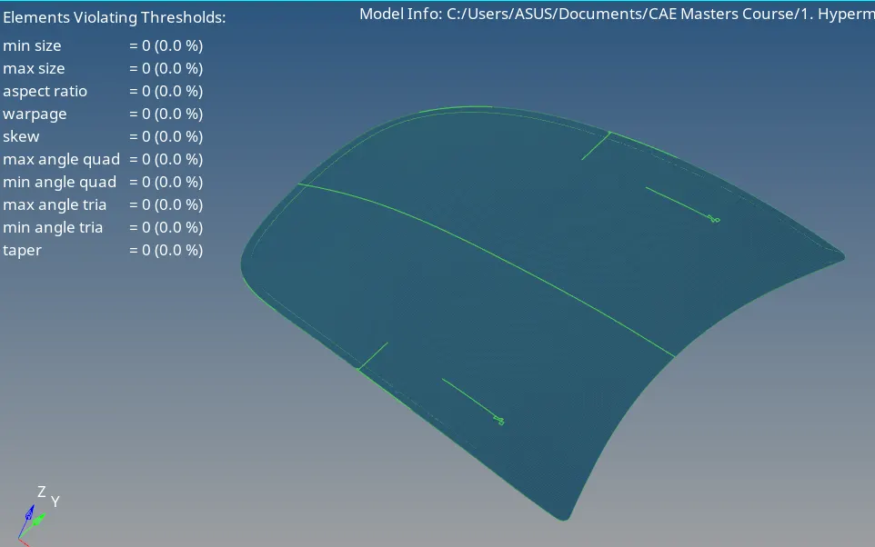
Fig.15 Meshed outer part of the hood
STEP 5: Clean up the elements to satisfy quality criteria
To satisfy the given criteria, the elements have to be adjusted. This can be done by using cleanup tools which can be accessed at 2D => Qualityindex => cleanup tools. Few examples of elements being cleaned up are given below.
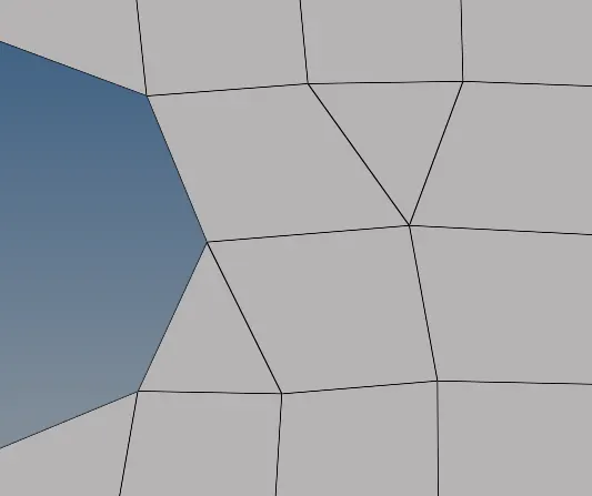
Fig.16a) Opposite tri elements
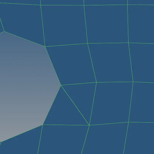
Fig.16b) Opposite tri elements are dragged towards each other
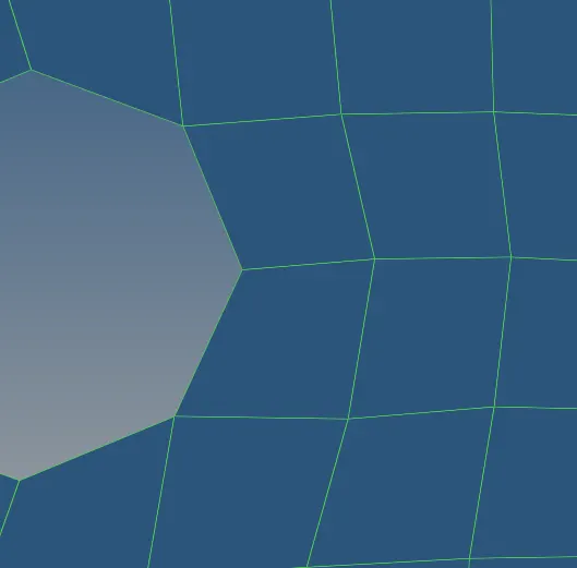
Fig.16c) Tri elements are combined
From the above three figures, opposite tri elements can be eliminated. First, drag one of the tri elements towards the other using "drag tria element". Then the two elements can be merged by removing one of the edges and making them into a quad element using "combine tria elements".
Some quad elements can fail for other criteria such as aspect ratio, skewness, quad angles, etc. This can sometimes be removed automatically using "Element Optimize".
This was done on the whole part in order to follow the quality criteria completely.
CONCLUSION: The midsurfaces of the various hood parts were successfully extracted followed by geometric cleanup. The meshing operation was performed on the surfaces followed by cleaning up of the elements in order to completely follow quality criteria.