Applying connectors onto a Frame Assembly using HYPERMESH
OBJECTIVE: To apply connectors between various parts of the given frame assembly model.
PROCEDURE:
In order to apply connectors between the various parts of the model, the following steps have to be followed:
1. Import geometry into Hypermesh.
2. Extract midsurface from the components and cleanup geometry
3. Mesh the midsurface of the components
4. Apply connectors onto the meshed components
STEP 1: Import geometry into Hypermesh
The frame assembly was imported into Hypermesh. The midsurface was already extracted and meshing was already done. Therefore, steps 2 and 3 are skipped in this report. The frame assembly is given below:
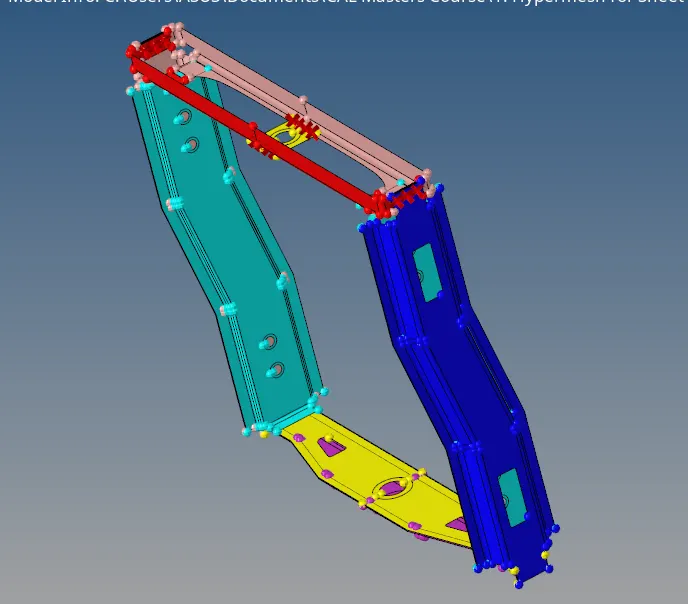
Fig.1 CAD model of assembly
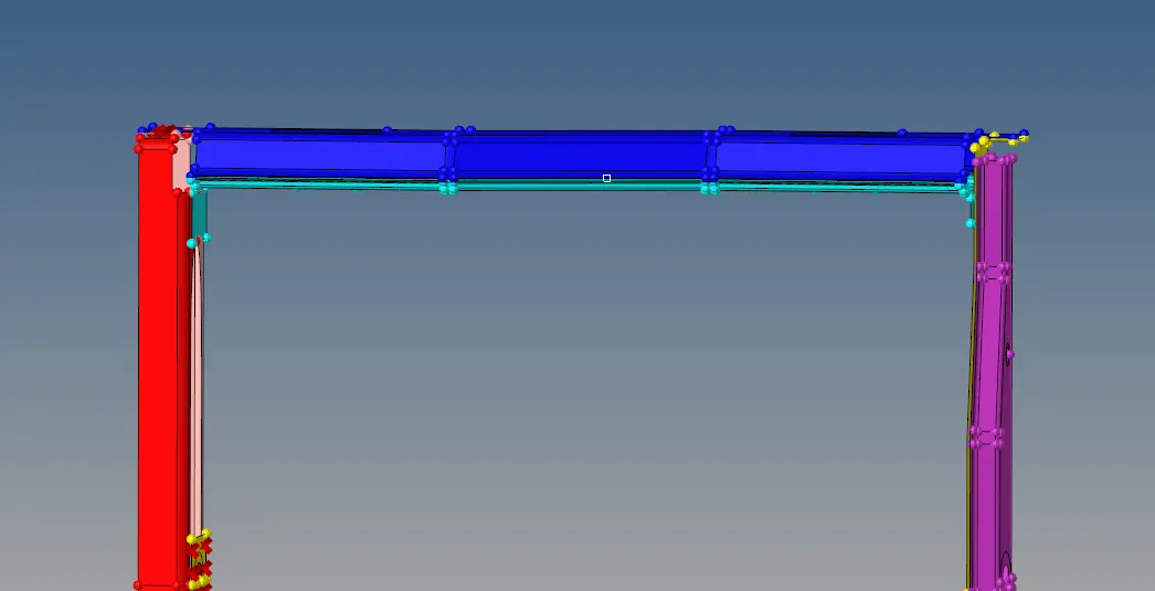
Fig.2 CAD model of assembly
STEP 4: Apply connectors onto the meshed components
There are several forms of connectors that can be applied upon the given model. The main focus of this report will be to apply 1D connectors, in particular, seam welds, spot welds and bolt connectors onto the assembly.
To apply bolt connectors, we can go to 1D => connectors => bolt and select required type of bolt. Then select the appropriate nodes where the bolt has to be applied, select the components over which the bolt connection takes place, and select "create hole if none"option. The bolt connection is now successfully applied.

Fig.3 Bolt connection option

Fig.4 Application of bolt connection and selection of bolt type
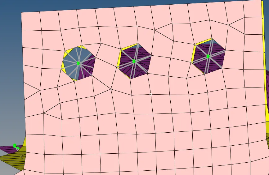
Fig.5 Bolt connection applied to two components
In order to apply seam weld, we can go to 1D => connectors => seam. The type of seam weld can be selected such as Seam quad (angled + capped + L), hexa (adhesive), etc as per requirement. Then the nodes onto which the connectors are to be applied are selected, and the components between which connectors are applied are selected. Hence, the connection is made.

Fig.6 Seam connector option

Fig.7 Application of seam connectors and selection of type of weld
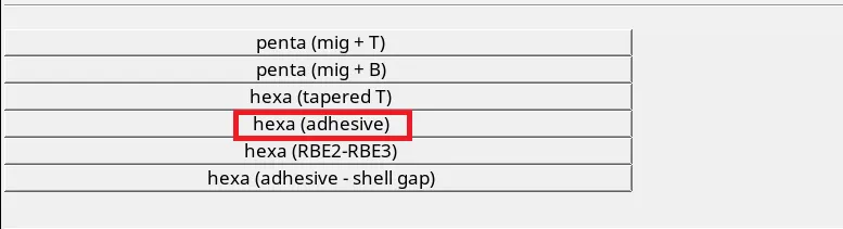
Fig.8 Some examples of types of seam welds
In below figure, the hexa (adhesive) option was implemented onto the blue and red components. The black box indicates the applied connectors.
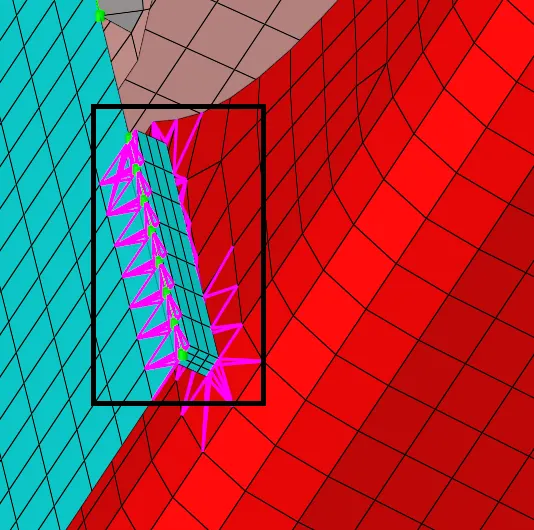
Fig.9 Hexa (adhesive) connector applied on two components
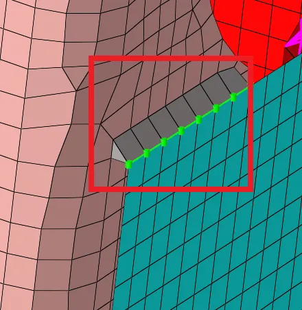
Fig.10 Quad (angled + capped + L) seam weld applied on two components
Similar to application of seam weld, spot weld connectors can also be applied by going to 1D => connectors => spot. In our case, rigid and spring type elements were used. The rigid type spot weld can be seen in figure 13 within the red box.

Fig.11 Spot connector option

Fig.12 Application of spot connector option
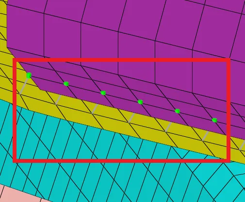
Fig.13 Spot weld connectors applied on two components
Similarly, at appropriate locations, appropriate connectors were applied onto the frame assembly. The final frame assembly is show in figure 14.
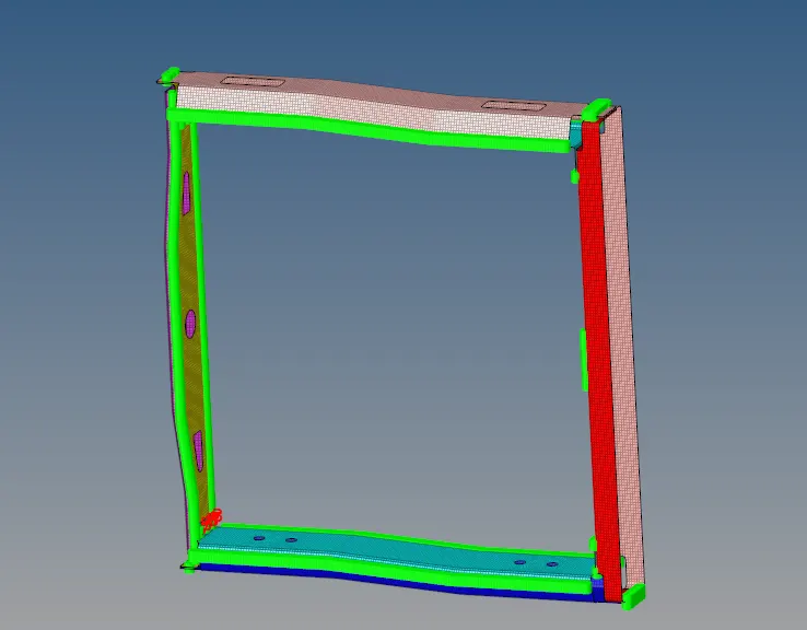
Fig.14 Final frame assembly with all connectors
CONCLUSION: The frame assembly was successfully added with connectors at appropriate locations.