LS-DYNA PROJECT 2 - Bird Strike on Plane Engine
AIM: To simulate a bird strike on the blades of an aeroplane engine using LS-DYNA.
PROCEDURE:
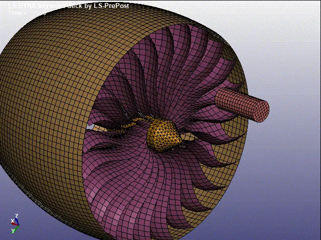
The model which consists of the engine blades, casing, hub and a simplified model of a bird are shown below:
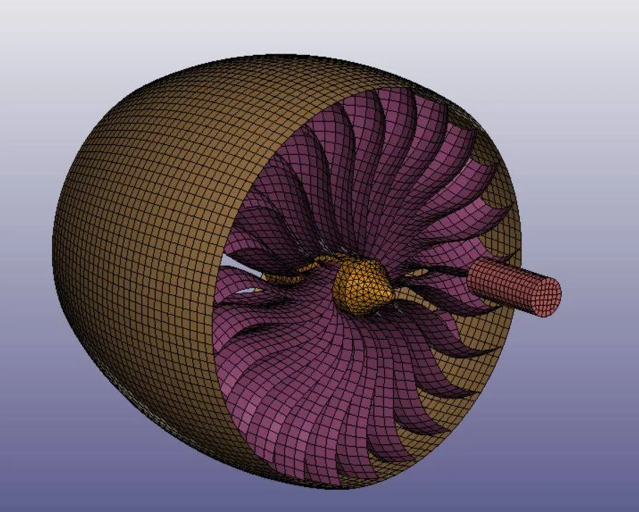
The casing, blades and bird are made of shell elements and the hub is made of solid elements. These element IDs, node IDs and part IDs are to be separated from one another and given unique ID numbers so that in complex scenarios it will be simpler to implement other simulations or for general debugging purposes.
Therefore, for the present simulation the following numbering system was implemented:
|
Part name |
Part ID |
Nodes ID |
Elements ID |
|
Casing |
1001 |
100000+ |
500000+ |
|
Blades |
1002 |
110000+ |
510000+ |
|
Hub |
1003 |
120000+ |
520000+ |
|
Bird |
1004 |
130000+ |
530000+ |
|
Parameter |
ID number |
|
Section |
10100+ |
|
Materials |
10200+ |
|
Boundary Conditions |
10300+ |
|
Node Sets |
10400+ |
|
Contacts |
10500+ |
|
Load Curves |
10600+ |
The section properties were given to each part by going to Model and Part => Keyword Manager => Section.
The below figure shows the various sections created:
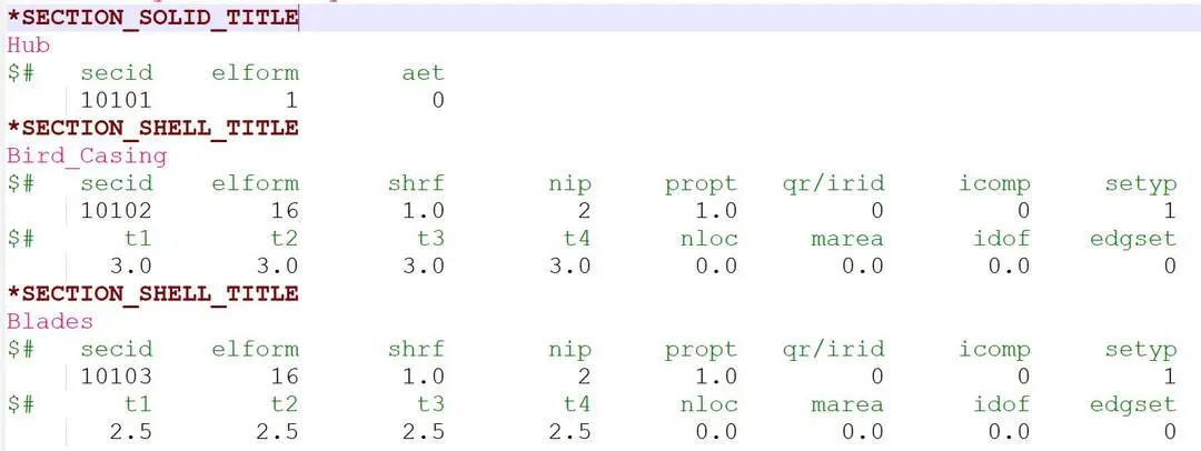
The hub was given a solid section of ID 10101. The casing and the bird were given shell sections of thickness 3 mm. The element formulation was given 16 with fully integrated elements. The blades were also same shell sections with 16 element formulation but thickness of 2.5 mm was given.
Materials allotted to the parts are given below:
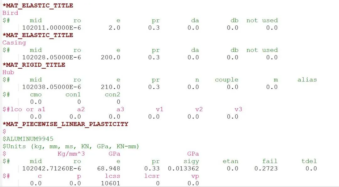
The bird and casing were given elastic material with bird having Young's modulus of 2 GPa whereas the casing has Young's modulus of 200 GPa. The hub was given a rigid material with properties of steel with Young's modulus of 210 GPa. The blades are the most important part of the simulation and were given a detailed piecewise linear plastic material properties with plastic region plotted below:
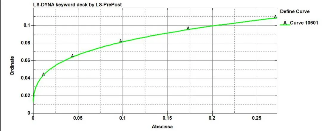
The ordinate is the stress and abscissa is plastic strain. This material was assigned to the blades to model the plastic strain behavior of the blades.
The two sides of the casing were given boundary conditions with all degrees of freedom constrained.:

The blades were given a rotational velocity of 0.2 mm/ms about x-axis and the bird was given translational velocity of 13.41 mm/ms (30 mph) along x-axis using initial velocity generation option:

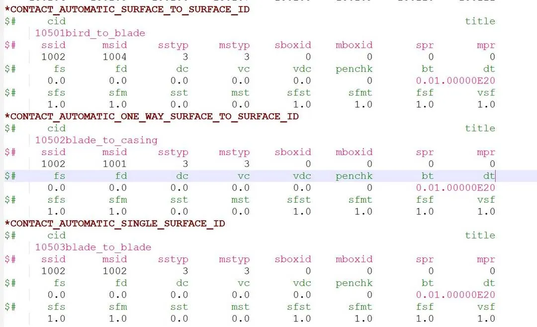
Contacts were provided to simulate contact between various parts. The first is between bird and blades in which bird is master and blades are slave. This was surface to surface contact. The second contact is between blades and casing which is also surface to surface contact. The third contact is self contact between the blades. This is single surface contact. The contacts are given below:
The various databases were set to get output blocks from the simulation and are given below:
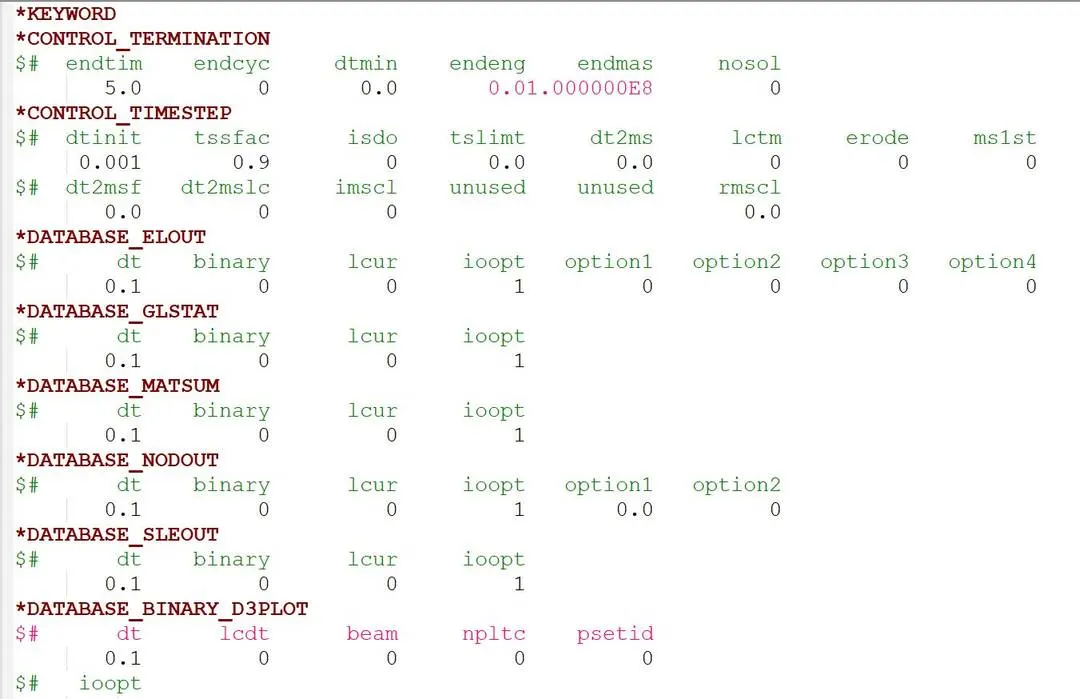
A termination time of 5 ms was given with timestep of 1 microsecond. The simulation was completed using explicit analysis. The results are shown below:
Stress contour:
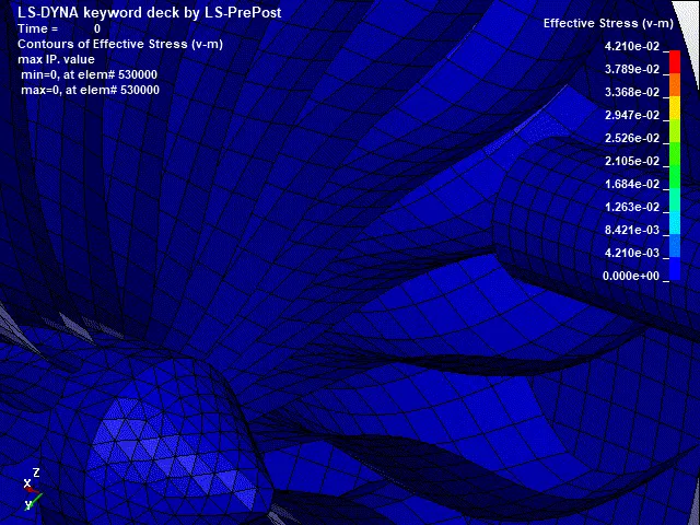
The Von-Mises stress variation with time is given below:
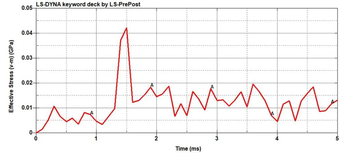
Maximum stress of 42.1 MPa is reached. The plastic strain variation is shown below:
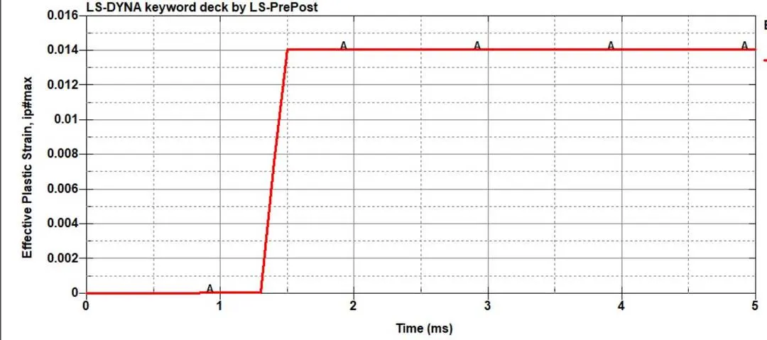
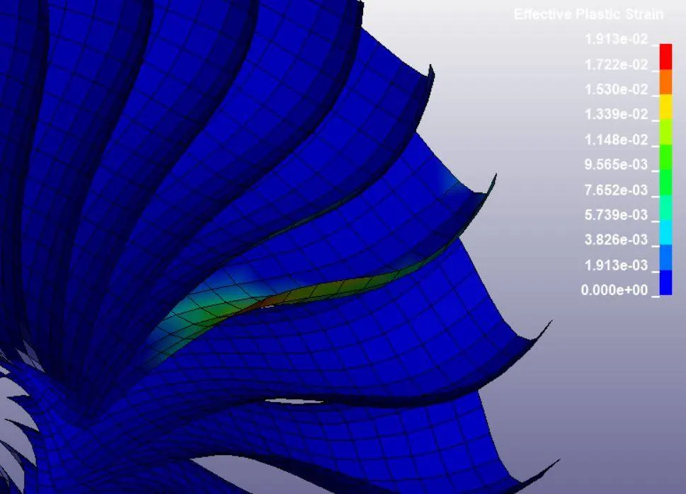
Maximum plastic strain of 0.014 was reached by the blades.
The energies such as total energy, internal energy and kinetic energy were plotted below:
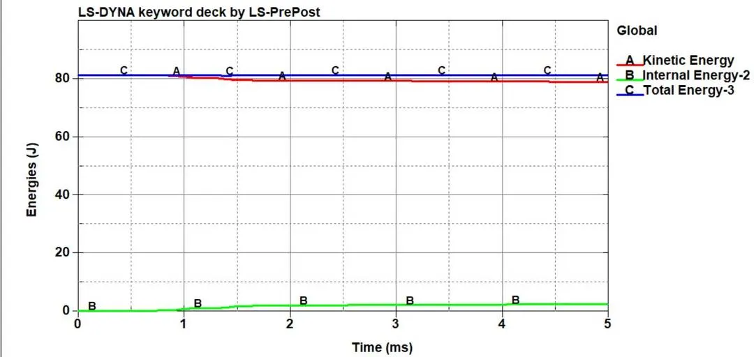
The reason for the low energies and stresses is because only the velocity of the bird was taken into consideration for this simulation. If we consider the velocity of the aircraft and add that velocity to get relative velocity, the impact can be more drastic. This can be done by simply changing the x-direction velocity of the bird to the required velocity for a more realistic scenario simulation. However, a small velocity of 30 mph is sufficient to induce plastic strain on the blades which means that a higher velocity can induce a much larger strain on the blades and potentially lead to an aeroplane crash. Therefore, the design and material implementation of the blades is crucial to prevent accidents.
CONCLUSION: The bird strike on aeroplane engine blades was successfully simulated and results were described quantitatively.
APPENDIX: DEBUGGING:
Case 1: Wobbling effect on blades
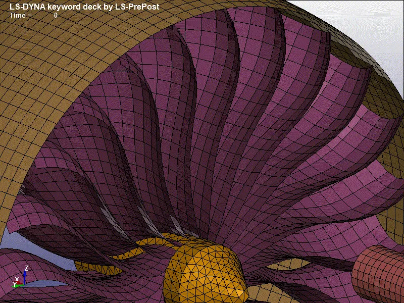
This was happening because blades were given initial velocity. This was changed to initial velocity generation and this removed the wobbling effect on the blades.
Case 2: No contact between blades and casing
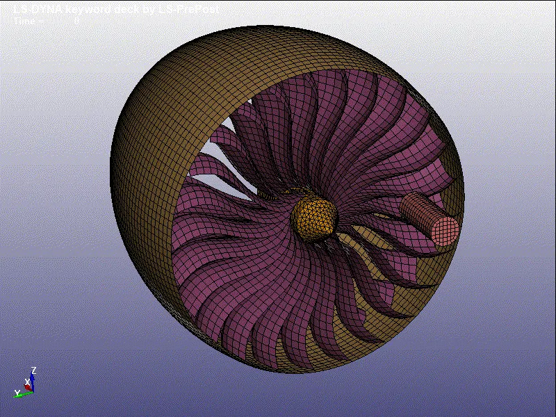
This error occurred due to no contact being present between blades and casing. This lead to the blades coming out of the casing. This was corrected by applying surface-to-surface contact between the blades and the casing.
Case 3: Blades failing due to high rotation speed
Initially, a high rotation speed was given to the blades which cause the blades to fail instantly in the simulation due to high centrifugal forces. This was quickly corrected by lowering the rotation speed of the blades.
Case 4: Bird going through blades due to improper contact
An improper node-to-surface contact was given between the blades and the bird. Due to a perpendicular contact between the two parts, a small penetration was occurring. This was resolved by giving surface-to-surface contact.
Case 5: Bird bouncing back after impact
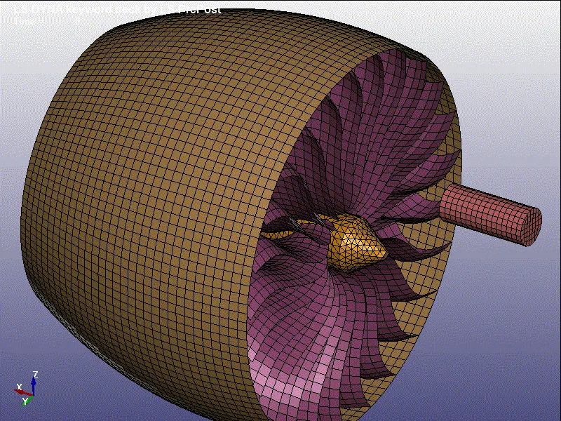
Initially, the bird's posterior nodes were given constraints in all degrees of freedom except x-translational. This led to the bird bouncing back after impact which is not realistic. Thus, the constraint was removed.