1D elements and Degrees of Freedom (DOFs) in Hypermesh
OBJECTIVES: To create 1D elements (Rod, Beam and Bar) at appropriate locations, define degrees of freedom on the given CAD model and to join the two components using spring element.
PROCEDURE:
The CAD model of the two components is given below.
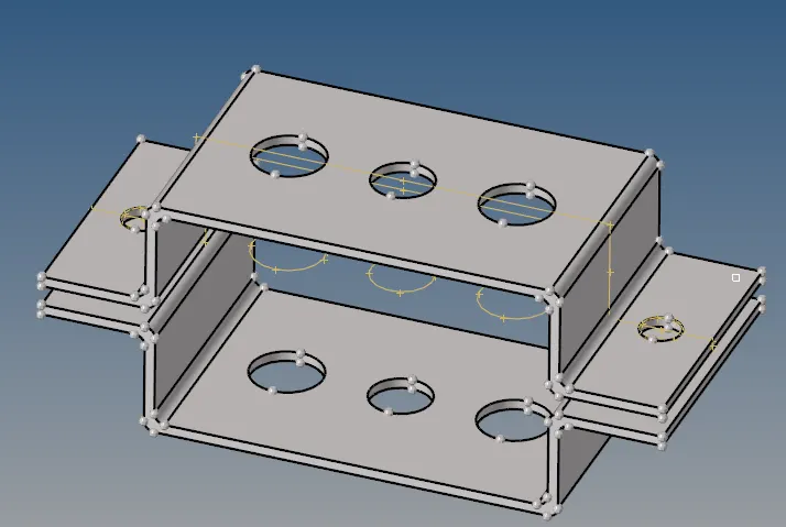
Fig. 1 CAD Model of the two bracket components
First, material definition was created by going to Create => Material. The Material was named Steel. Property definition was created by going to Create => Property. The property of the bracket was set with a thickness of 5 units and material Steel was set. The property type was set to PSHELL.
Midsurface of the two components was extracted using GEOM => midsurface => autoextraction. Extraction options were set to skin offset in order to get the most accurate midsurface. The extracted midsurface was assigned to the property that was created earlier. Prior to meshing the midsurface, washer split was made on the holes using GEOM => quick edit => washer split with an offset value of 5.
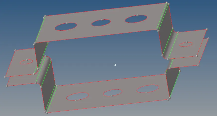
Fig.2 Midsurface of the two components
A 2D mesh was created by going to 2D => automesh and element size of 8 was used with mixed mesh type.
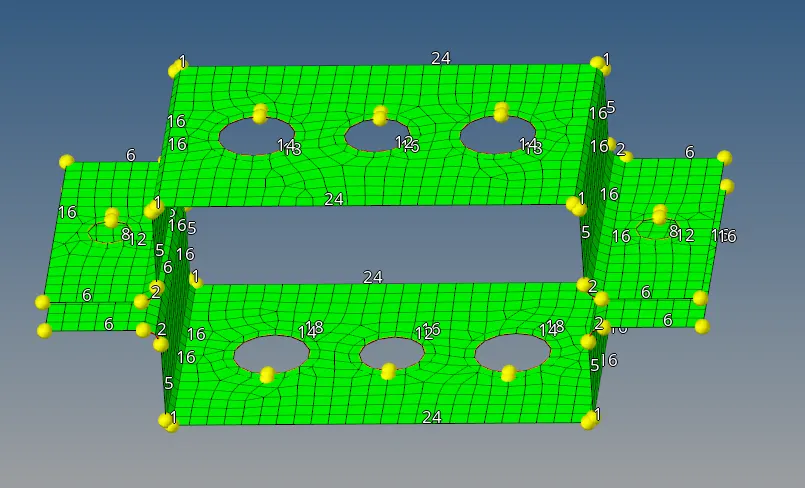
Fig.3 Initial mesh of the midsurface
Mesh around the holes was further refined by increasing the number of nodes.
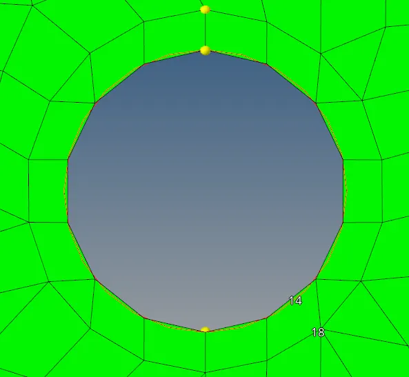
Fig.4a) Meshing around the holes before adjustment
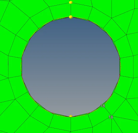
Fig.4b) Meshing around the holes after adjustment
Similarly, more nodes at fillets were introduced in order to mesh the fillet more accurately shape-wise.
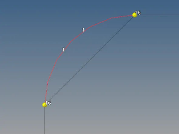
Fig.5a) Meshing of fillet before adjustment
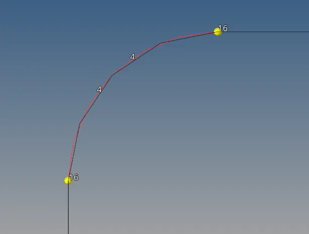
Fig.5b) Meshing of the fillets after adjustment
1D elements were placed on the nodes around the holes a,b,c,d and e as specified below:
Holes a - RBE2 link with DOF1, DOF2 and DOF3
Holes b - RBE3 link with all DOFs constrained.
Holes c - RBE3 link with DOF1, DOF2, DOF4 and DOF5
Holes d and e - RBE2 link
RBE2 link distributes load uniformly whereas RBE3 link distributes load based on distance from the central node.
Mass of magnitude 10 was also added on holes d and e using 1D => masses => create with magnitude 10 and element type CMASS1.
The rod, beam and bar elements' cross-section properties were added using 1D => HYPERBEAM => Standard Section. The box, I beam and cross element values were added at the HYPERBEAM section with appropriate dimensions. Using Create => Properties, the properties for the three elements were added and appropriate cross-sections were assigned to these properties.
These elements were added to the component using the 1D menu. Springs were added to the ends of the brackets using 1D => Springs => Create.
The final results are shown below.
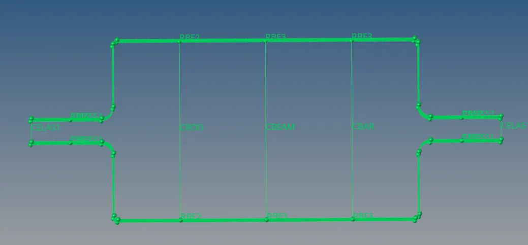
Fig.6 Side view of component with all the 1D elements added
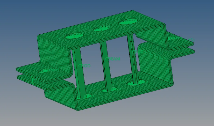
Fig.7 Isometric view of the components with a detailed view of the 1D elements
CONCLUSION: The component was successfully meshed using 2D meshing. The 1D rod, bar and beam elements were successfully added and the aforementioned degrees of freedom were assigned. The two components were joined using spring elements.