2D meshing of the backdoor of a car using HYPERMESH
OBJECTIVE: To extract midsurface of backdoor of a car and perform geometric cleanup. To mesh the midsurface of the backdoor and to cleanup the elements according to the given quality parameters.
PROCEDURE:
In order to complete the meshing of the backdoor according to the required quality parameters, the following steps have to be followed:
1. Import geometry into Hypermesh
2. Extract midsurface of the components
3. Perform geometric cleanup of midsurface
4. Perform 2D meshing of the midsurface
5. Cleanup the elements in accordance with the required quality parameters
STEP 1: Import geometry into Hypermesh:
The CAD model of the backdoor has to be imported into Hypermesh. The CAD model once imported is split into three main components. The components are inner panel, upper body and lower body. The CAD models are shown in the figures below.
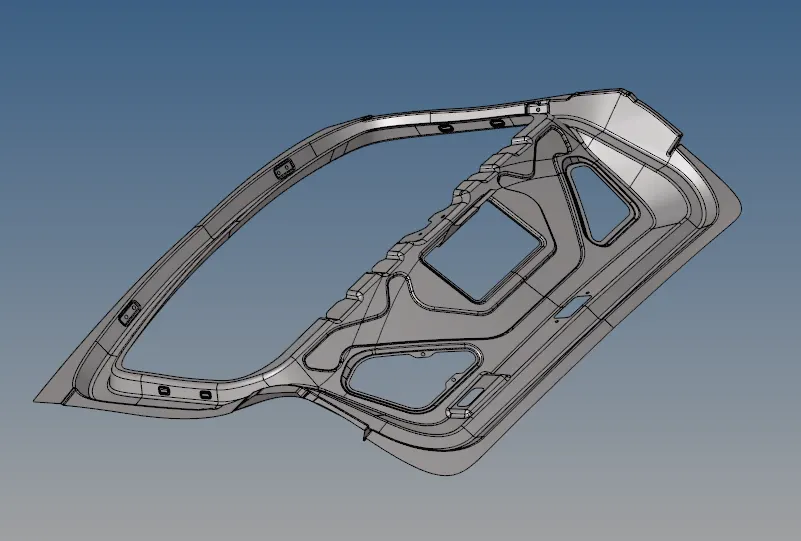
Fig.1 CAD model of inner panel
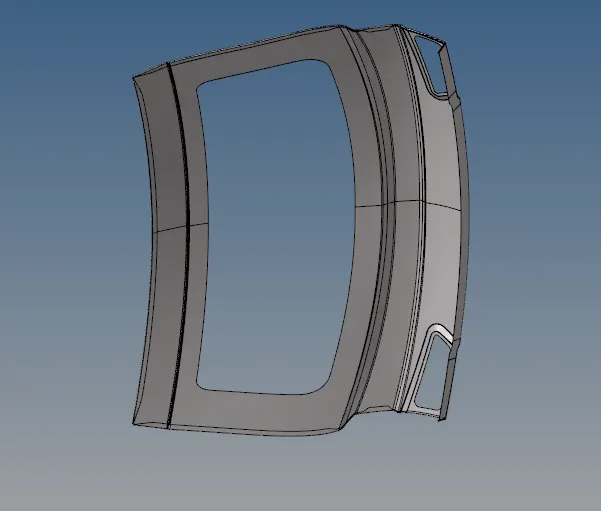
Fig.2 CAD model of upper body
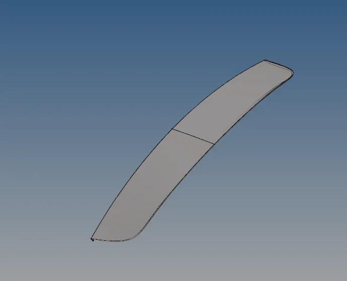
Fig.3 CAD model of lower body
STEP 2: Extract midsurface of the components:
The midsurface can be extracted either manually or automatically. In this case, midsurface was extracted automatically. To extract midsurface, we can go to GEOM => Midsurface => Auto midsurface option. In extraction options, skin offset method was selected as the algorithm for extraction of midsurface.

Fig.4 Midsurface option

Fig.5 Extraction options
STEP 3: Perform geometric cleanup of midsurface:
The midsurfaces were geometrically cleaned using GEOM => quick edit.

Fig.6 Quick edit tools
The following tools are useful for performing geometric cleanup in this case:
1. Toggle Edge: This tool can be used to toggle and change the type of edge. There are several kinds of edges seen in Hypermesh. The various kinds of edges present in Hypermesh can be seen in the below diagram.
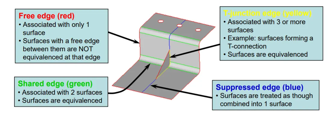
Fig.7 Different types of edges
The "Toggle Edge" tool can be used to change one edge to another. This is especially useful to maintain quality criteria of the mesh. This tool is used to suppress shared edges that can cause elements to be of a very low size and which can fail the minimum edge requirements. It can also be used to toggle free edges into shared edges. In some cases, Hypermesh incorrectly creates free edges in places where it should be a shared edge. In this case, toggling a free edge into a shared edge eliminated the problem.
2. Project point: Project point tool is used to project a point from one line to another line.
3. Split surf - node: This tool is used to split a surface using two nodes as reference. This tool is utilized simultaneously with project points in order to prepare grid-like surfaces in order to get proper flow of mesh in certain cases.
4. Split surf - line: This tool is used to split a surface using a node and a line as reference. This tool can be used to circumvent the projection of a point onto a line and then splitting using nodes. Instead the surface is split directly by choosing a node on one line and choosing another line onto which the surface is being split upon.
A combination of the above tools was used to create grid-like surface splits onto the lower body of the backdoor which can be seen below:
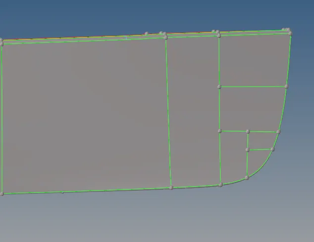
Fig.8 Grid-like surfaces edited onto the midsurface of lower body
Similarly, in other components, geometric cleanup was done in order to ensure that minimum and maximum element sizes would be adhered to when meshing would be done on the surfaces. One such examples from the inner part of the backdoor is shown in the image below:
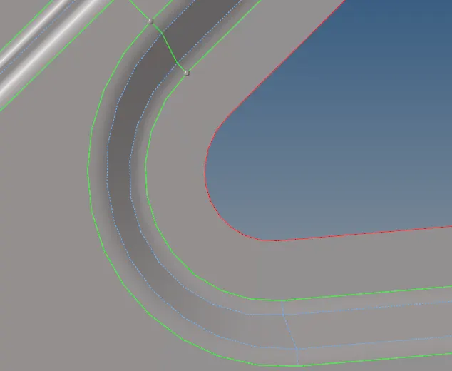
Fig.9 Suppressed edges in inner panel
Now that the edges are suppressed, the mesh will not fail minimum length criteria. This is just one example. Several lines such as this have to be toggled for the complete geometry to meet the quality requirements. Therefore, geometric cleanup is one of the most important steps to perform.
STEP 4: Perform 2D meshing on the midsurfaces:
Following the extraction of midsurface and performance of geometric cleanup, the midsurface needs to be meshed using 2D shell elements. This can be done by going to 2D => automesh. Mixed elements were selected with target element size of 5.

Fig.10 Automesh option

Fig.11 Meshing using automesh tool
Quality criteria parameters were added using Preferences => Criteria File settings.
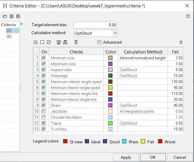
Fig.12 Quality criteria settings
An example of meshing performed on the lower body of the backdoor is shown below:
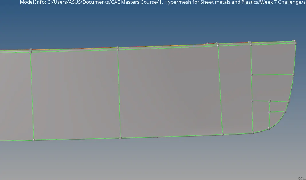
Fig.13 Lower body before mesh
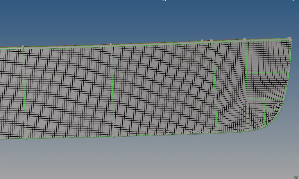
Fig.14 Lower body after mesh
In case of upper body and lower body, the components were symmetrical with respect to one axis. Therefore, it is sufficient to mesh one half of the component and then duplicate the elements on one side and use reflect tool to automatically mesh the other half of the component. The reflection can be done by going to Tool => Reflect.
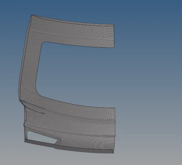
Fig.15 Half of upper body meshed

Fig.16 Reflect option

Fig.17 Reflection of elements using reflect tool
Select the elements, duplicate them onto the current component, then reflect by selecting the axis of symmetry and a base point.
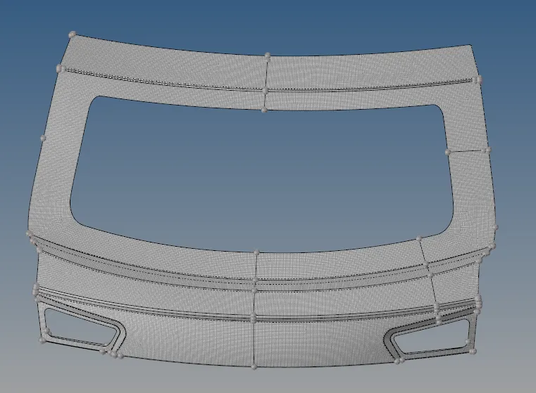
Fig.18 Upper body after reflection of elements
STEP 5: Cleanup the elements in accordance with required quality parameters:
The quality criteria that was added previously has to be followed by maximum elements possible. This can be checked and cleaned up by going to 2D => quality index => cleanup tools.

Fig.19 Quality index option

Fig.20 Cleanup tools option

Fig.21 Several tools available to clean up the elements
In Cleanup tools, we find several tools that can be used to optimize the elements to adhere to the quality parameters. One such example of usage of "Place node" tool is shown below:
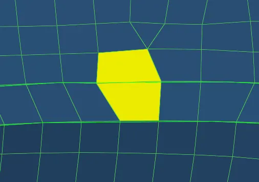
Fig.22 Element before Place node was used
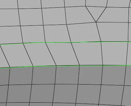
Fig.23 Elements after Place node was used
"Drag tria element" tool can be used in many cases to move tria elements. some cases are show below in cases such as trias touching each other, or trias pointing at edges.
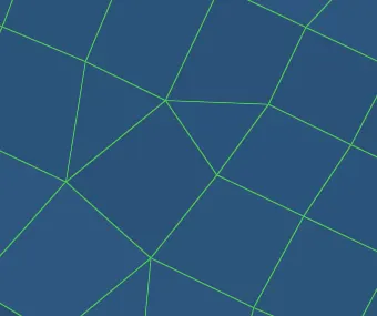
Fig.24 Trias touching each other
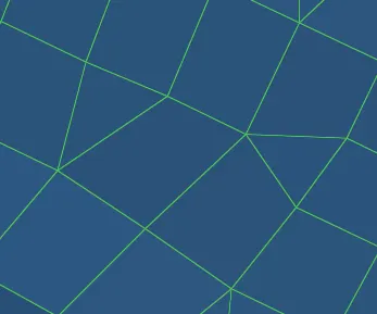
Fig 25 Trias moved away from each other
Warpages exist in several elements which can be removed by using translate tool which can be accessed at Tool => Translate. using this tool, warpage can be transferred from high warpage area to low warpage area and hence optimize the elements.
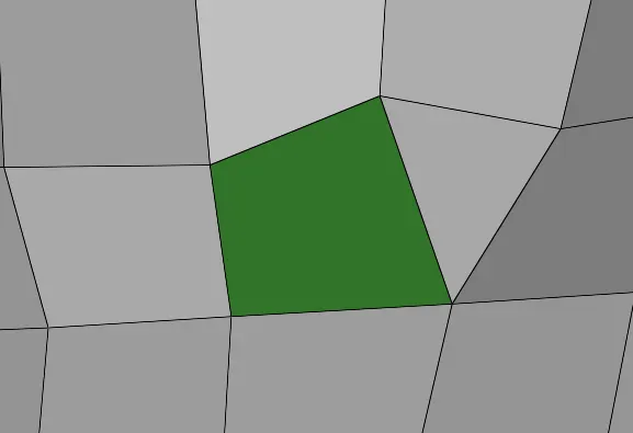
Fig.26 Element with warpage

Fig.27 Translate tool

Fig.28 Remove warpage using translate tool
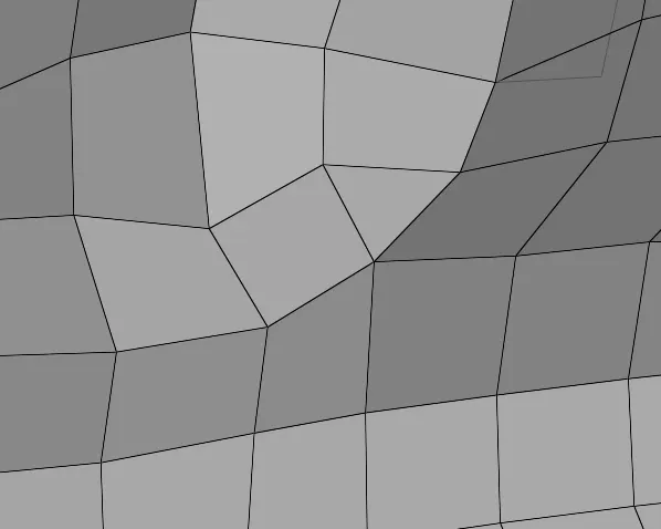
Fig.29 Warpage of the element removed
Elements surrounding holes need to be optimized for better mesh flow. This can be done by having even number of nodes on the holes. One example of this is given below:
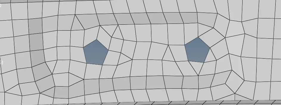
Fig.30 Poor mesh flow surrounding holes
Go to GEOM => Nodes and select Arc center and place a node at the center of the hole. Then remesh the elements surrounding the hole and place even number of nodes onto the hole. This can be followed by rotating the nodes onto appropriate angles in order to improve the mesh flow. This rotation can be done by using the rotate tool by going to Tool => Rotate.

Fig.31 Nodes option

Fig.32 Placing node at center of arc using node tool
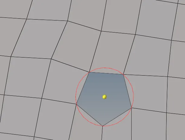
Fig.33 Node placed at center of arc
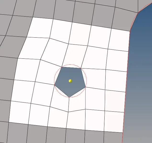
Fig.34 Elements around the hole are selected
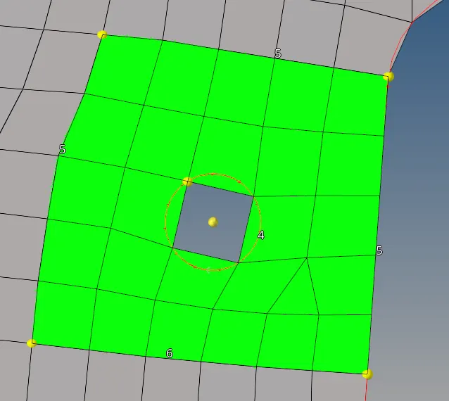
Fig.35 Elements around the hole are remeshed

Fig.36 Rotate tool
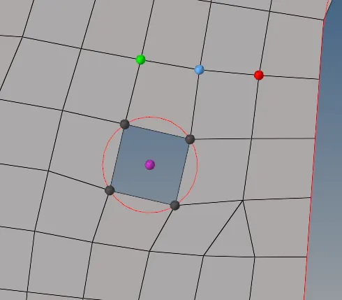
Fig.37 Usage of rotate tool onto the nodes of the mesh
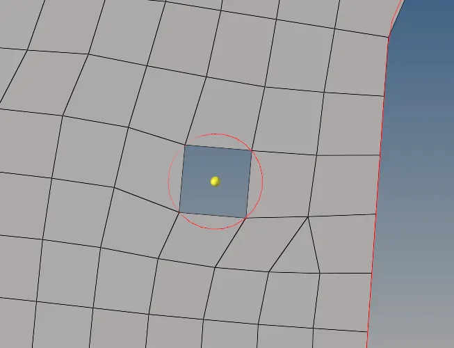
Fig.38 The nodes are rotated appropriately to improve mesh flow

Fig.39 Edges tool

Fig.40 Finding free edges using edges tool
Finally, there are several free edges where the elements are not equivalenced and this needs to be adjusted. The free edges can be detected by going to Tool => edges => find edges. The red lines indicate free edges. In the below figure, the red line needs to be removed by equivalence. Some of the free edges can be automatically removed by clicking on "equivalence" on the edge tool. Others have to be manually removed by going to the "Replace" option which can be done by going to 2D => Replace.
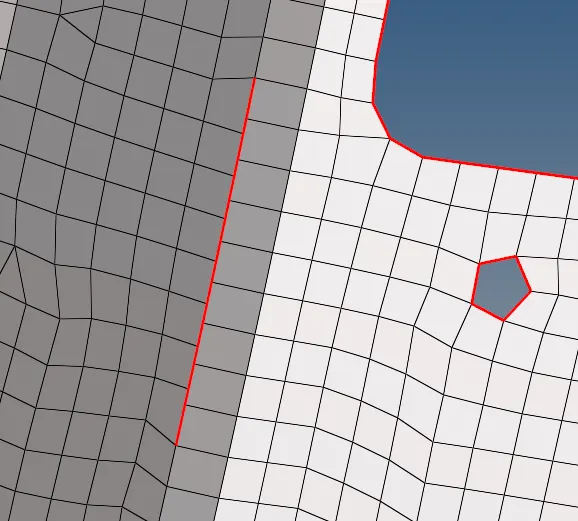
Fig.41 Free edge found on inner panel

Fig.42 Replace tool

Fig.43 Providing equivalence to nodes using replace tool
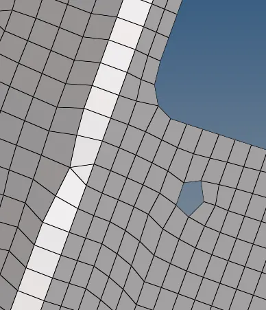
Fig.44 Free edge removed post equivalence
The final meshes of the components are given below:
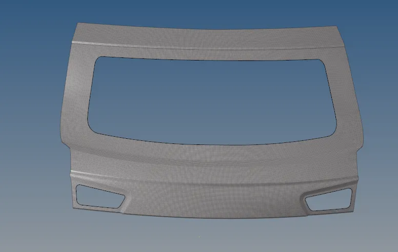
Fig.45 Final mesh of the upper body
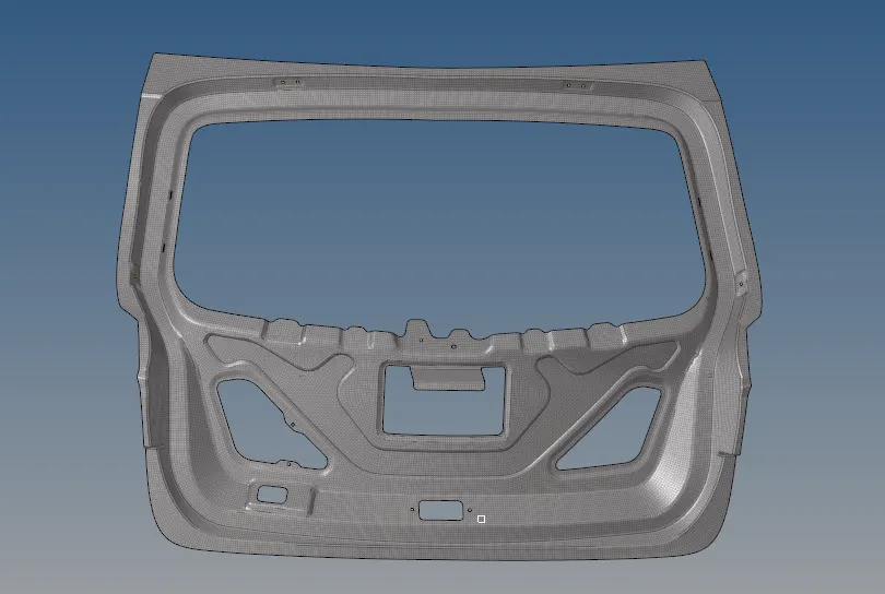
Fig.46 Final mesh of the inner panel
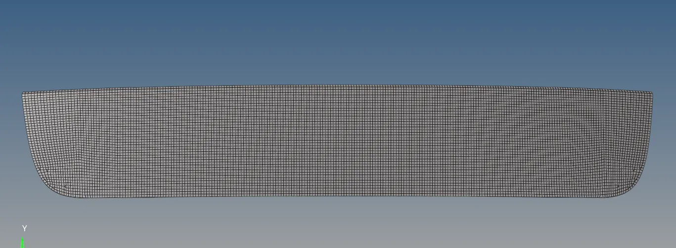
Fig.47 Final mesh of the lower body
CONCLUSION: The midsurface of the three components of the backdoor of a car were successfully extracted and geometric cleanup was performed. The 2D meshing of the midsurfaces was successfully completed and the quality criteria were met as much as possible by performing element cleanup