Modelling Spotwelds in LS-DYNA
Aim: To simulate a crash test of the given component by welding the two parts using beam elements and solid elements by using LS-DYNA and LS-PrePost. To compare the results obtained by using the two different spotweld types.
Procedure:
Initially, the model is imported into LS-PrePost and is shown below:
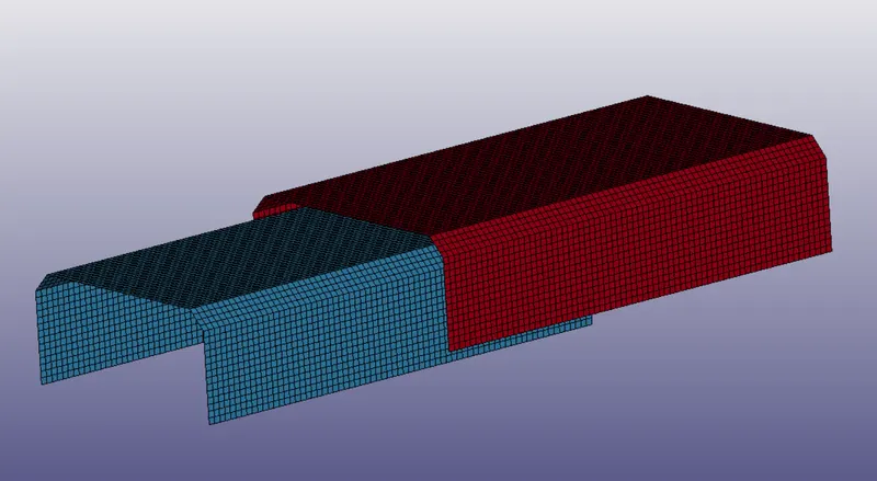
The model is welded using beam elements by going to Element and Mesh => element generation can creating beam element between appropriate nodes. The weld is shown below:
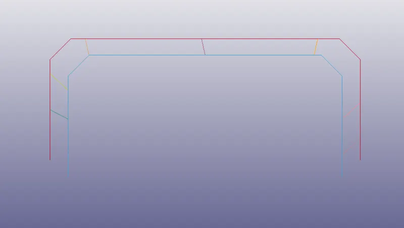
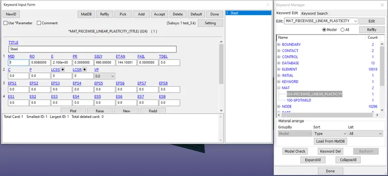
7 weld spots are created between the two parts. Next, material property is given to the shell elements and beam elements. Both are assumed to be made up of steel. The material properties are created by going to Model and Part => Keyword Manager => MAT. The shell elements are given as type024-piecewise linear plastic material and the card is shown below:
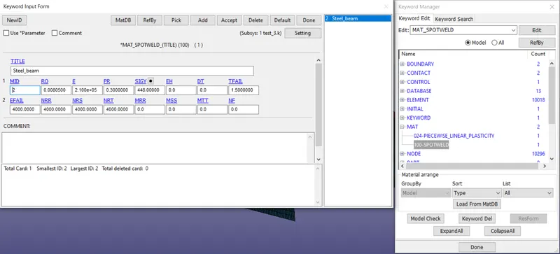
The beam welds are given type100-Spotweld material property as shown below:
The sections have to be defined for these materials. A shell section and a beam section are created for the respective elements. The properties can be assigned in Keyword manager by going to SECTION keyword. The shell section properties are shown below:
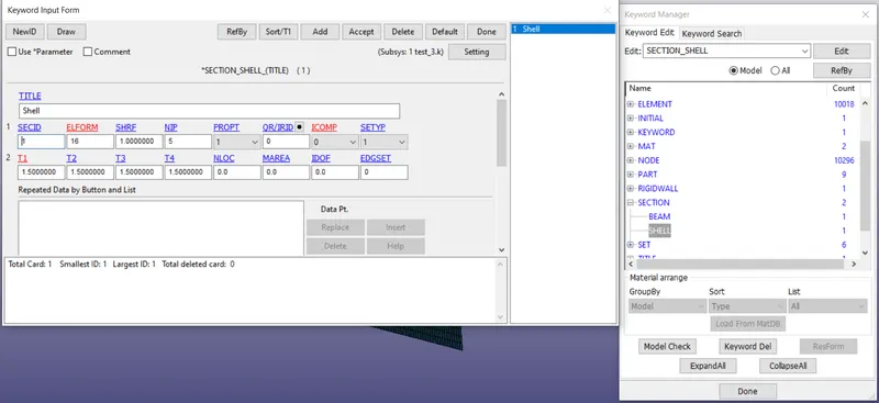
Element formulation 16 is used to create fully integrated shell elements with thickness of 1.5 mm. The beam element section properties are given below:
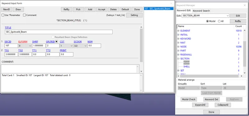
A cylindrical element with 3 mm thickness is created with ELFORM = 9 which is a specialized spotweld beam element formulation.
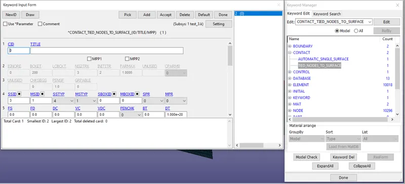
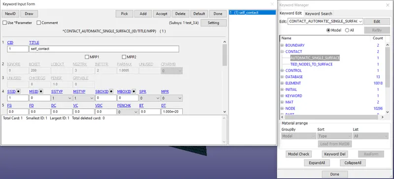
Two contacts are given to the simulation. One is contact between spotweld and shell elements. The second contact is self-contact of the shell elements. This is given in Keyword manager by going to keyword named Contact. The contact between shell elements and spotweld is called Tied_Nodes_to_Surface. The properties are given below:
Self contact properties are given using Automatic_single_surface as given below:
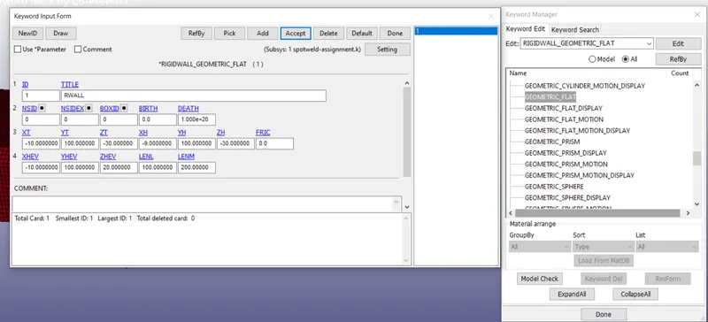
Rigid wall is created in keyword manager by going to RigidWall => Geometrical_FLat_Display. The rigid wall properties are given below:
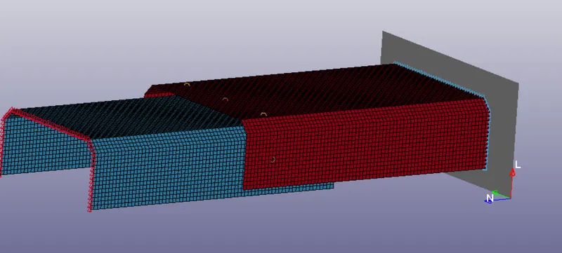
The initial velocity of 10 mm/ms is given by going to Initial => Velocity in keyword manager to collide with the rigid wall. The final setup looks as shown below:
The necessary output blocks are generated at Database keyword. Termination time of 3 ms is given at Control => Termination.
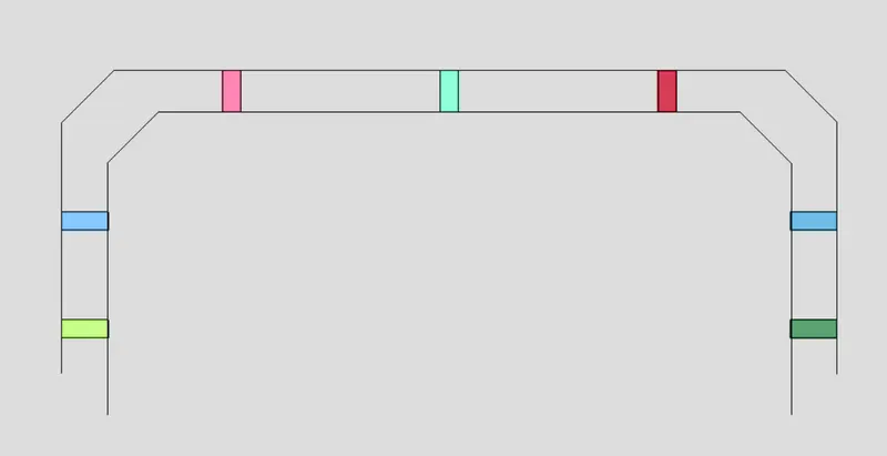
This simulation is to be compared to solid welds. The solid welds are created at the same place as beam elements. Except for beam elements, we select solid element and create solid welds between the two parts as shown below:
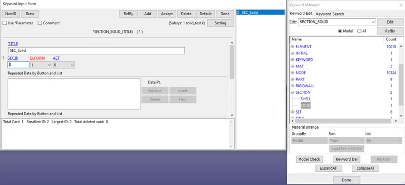
A new section property is defined for solid elements as shown below:
The two simulations are done using LS-DYNA and post-processing is done in LS-PrePost.
RESULTS:
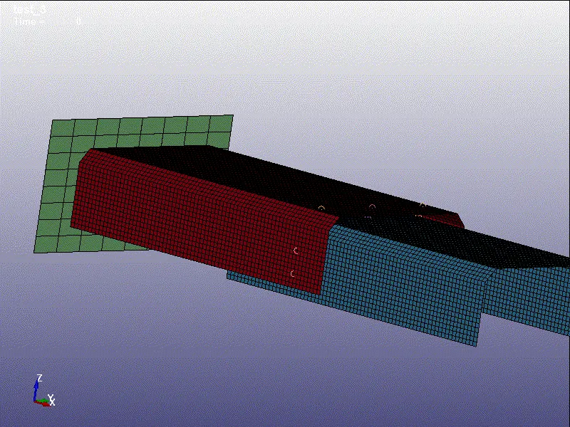
The beam welded components undergoing a crash test are shown below:
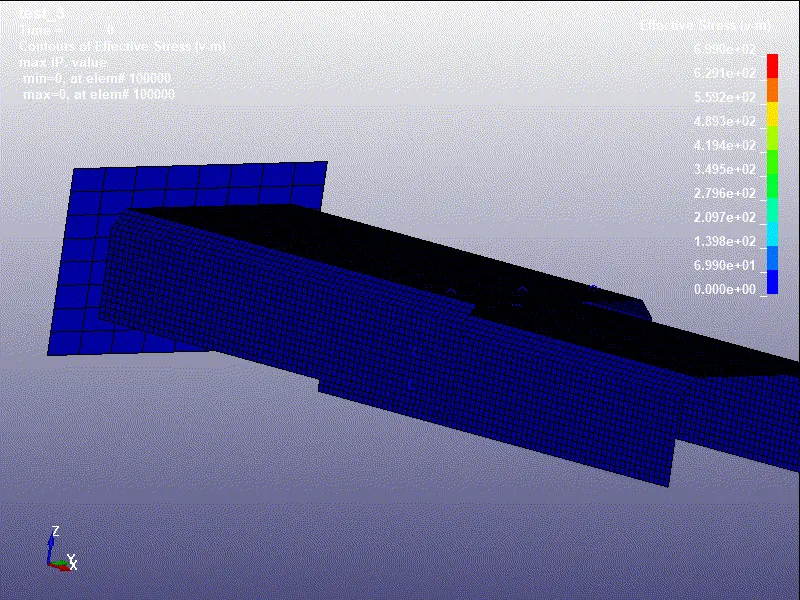
Von-mises stress contour:
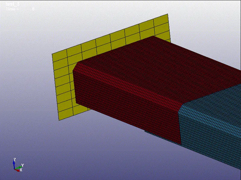
The solid welded components undergoing crash test is shown below:
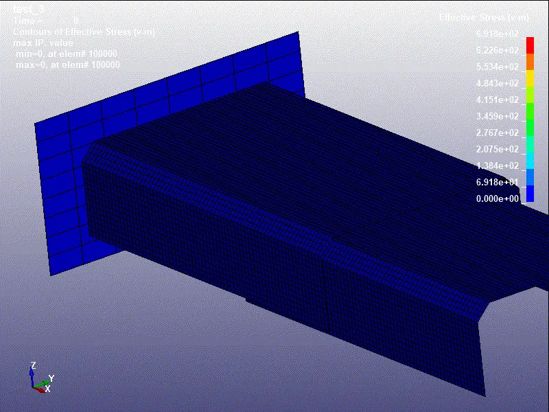
Von-Mises Contour:
1. Energies
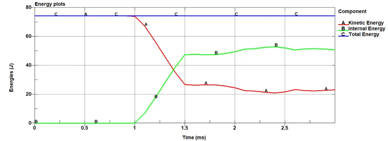
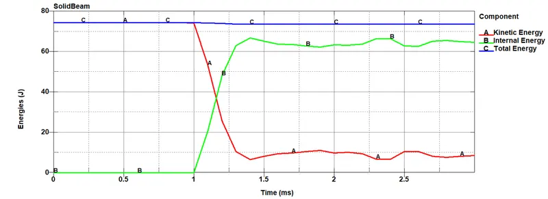
The kinetic, internal and total energies were plotted for the two simulations as shown below:
Beam welds:
Solid welds:
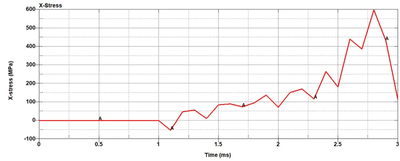
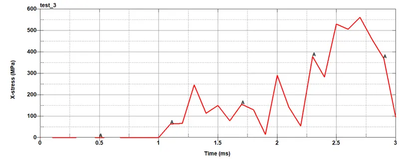
2. Stress in x-direction
Beam Welds:
Solid Welds:
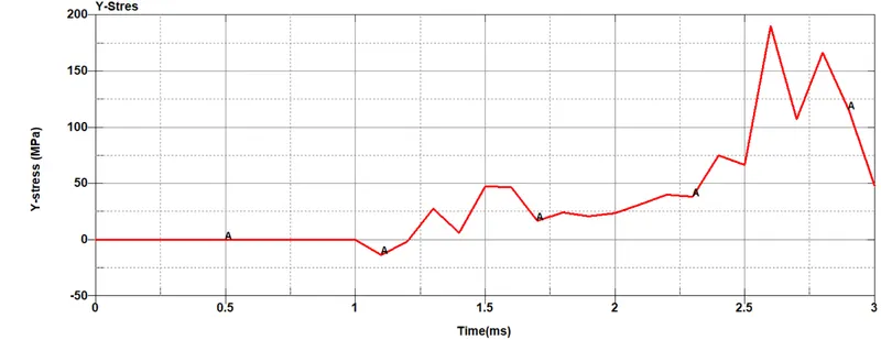
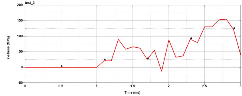
3. Stress in y-direction
Beam Welds:
Solid Welds:
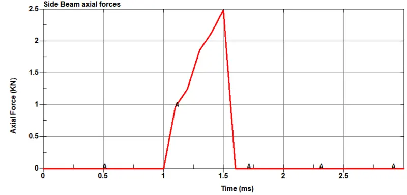
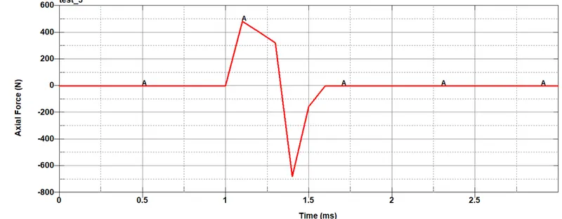
4. Axial force at weld
Beam Welds:
Solid Welds:
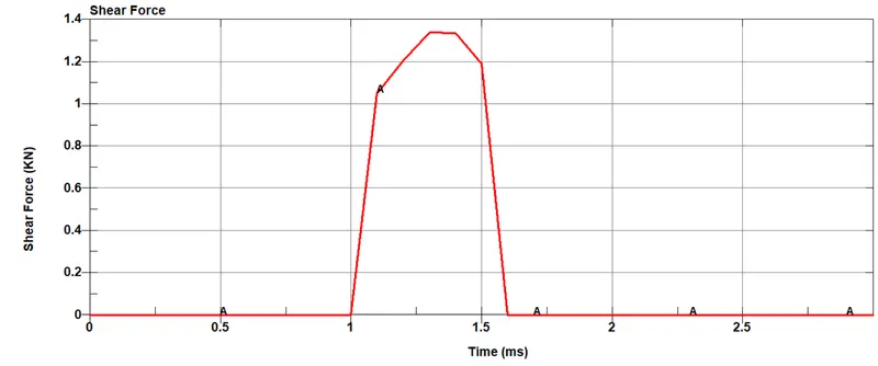
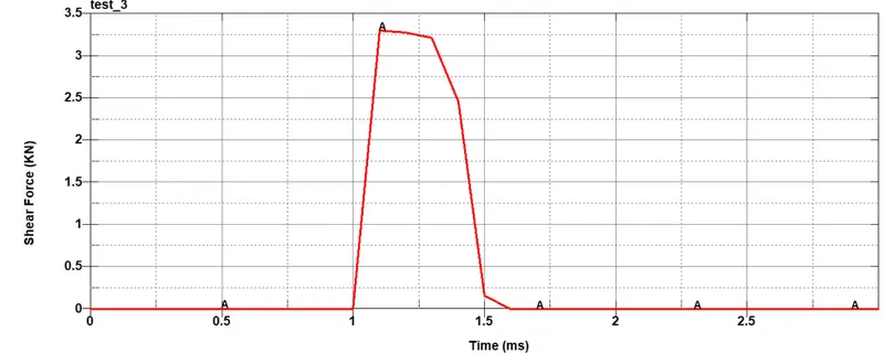
5. Shear force at weld
Beam Welds:
Solid Welds:
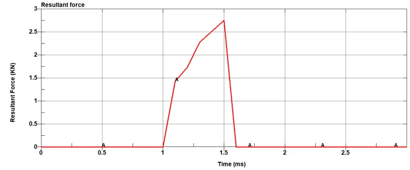
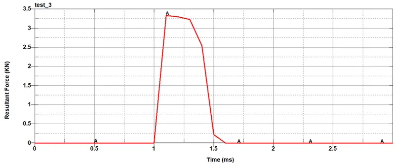
6. Resultant force at weld
Beam Welds:
Solid Welds:
The results from the above plots can be summarized by the below table:
|
Property |
Beam Weld |
Solid Weld |
|
Axial Force |
2.49 KN |
-0.679 KN |
|
Shear Force |
1.34 KN |
3.3 KN |
|
Resultant Force |
2.76 KN |
3.35 KN |
|
Initial Kinetic Energy |
74.4 J |
73.6 J |
|
Final Kinetic Energy |
23.1 J |
8.56 J |
|
Final Internal Energy |
50.9 J |
64.6 J |
|
Von-Mises stress |
699 MPa |
691.8 MPa |
|
Plastic Strain |
0.143 |
0.195 |
|
X-Axis stress |
598 MPa |
562 MPa |
|
Y-Axis stress |
191 MPa |
155 MPa |
As can be seen, the beam elements allow deviation of the attached shell elements with respect to y-axis. Thus, although they have higher axial force impacted on them, they have lower shear force and less resultant force when compared to the solid elements. The solid elements have to endure higher resultant force.
As a result, the shell elements of the solid weld absorb more energy as is shown in the Internal Energy vs Time graphs. This also results in higher plastic strain for the solid welded shell elements.
CONCLUSION: The given components were welded successfully with beam and solid elements and made to undergo a crash test against a rigid wall. The results obtained were compared quantitatively.