Transient Structual Analysis of a Universal Joint with spring using ANSYS Workbench
AIM: To conduct a transient structural analysis of a universal joint with a spring using ANSYS Workbench.
PROCEDURE:
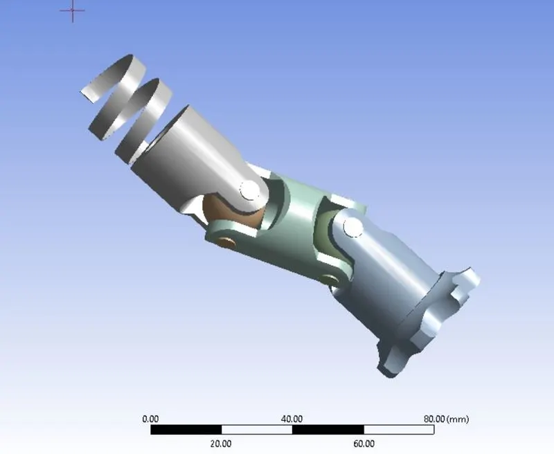
The universal joint with spring attached was imported into ANSYS and the geometry of the assembly is shown below:
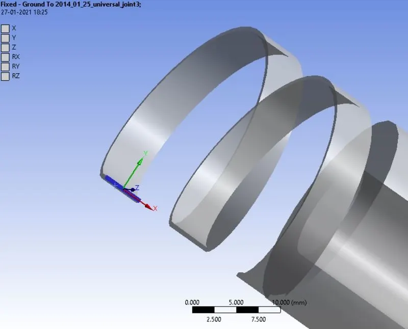
The unattached end of the spring is fixed using fixed joint as shown below:
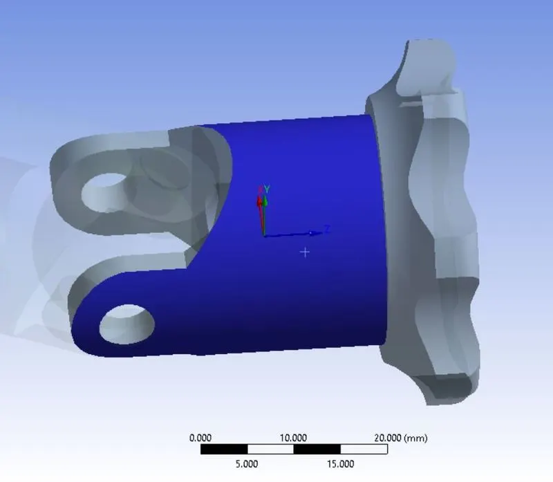
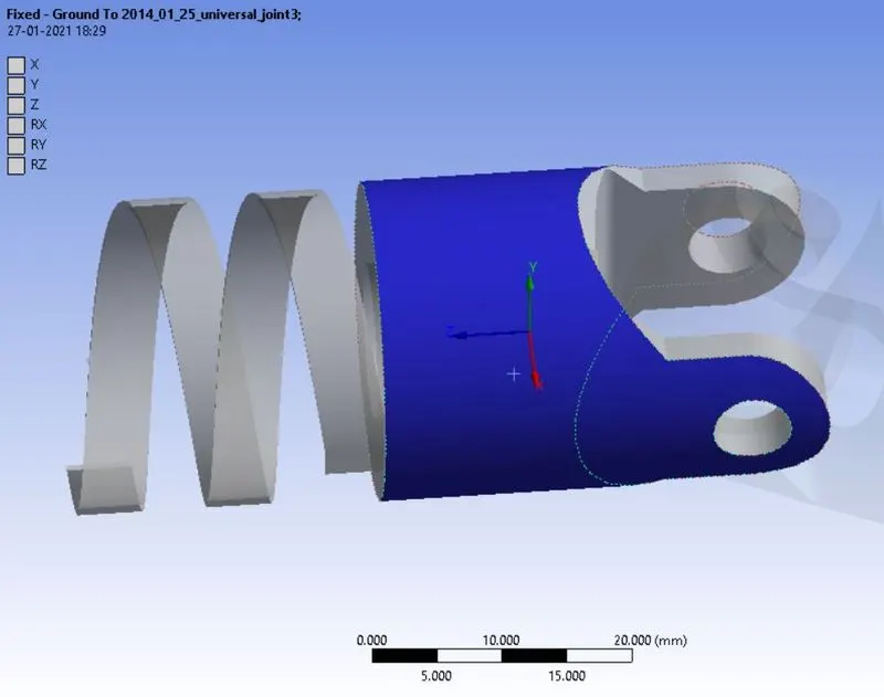
The shafts of the two universal joints are given body-to-ground revolute joint as shown below:
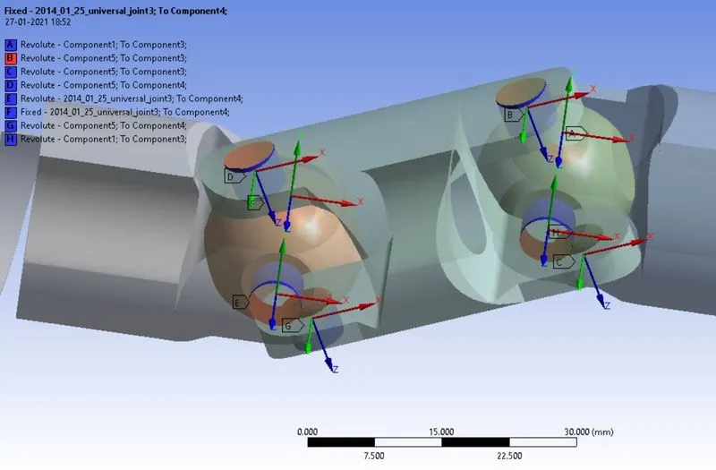
At location of joints where motion transfer occurs, a body-to-body revolute joint is given so that motion transfer can be simulated. These joints are shown below:
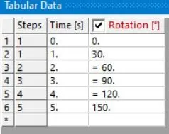
The revolute joint given to one end of the universal joint is given joint load in the form of rotation in 5 steps reching 150 degrees as shown in the table below:
The rotational movement causes spring's reaction to activate which causes a motion of its own. This causes the force to act on the joint. This will be demonstrated by the simulation results in the upcoming sections. The material used will be changed in each case. Materials used are Structural Steel, Stainless Steel and Titanium Alloy.
Case 1: Material = Structural Steel:
The entire assembly was assigned material of Structural Steel. The simulation was solved for stress and deformation. The stress contour is given below:
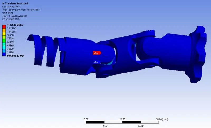
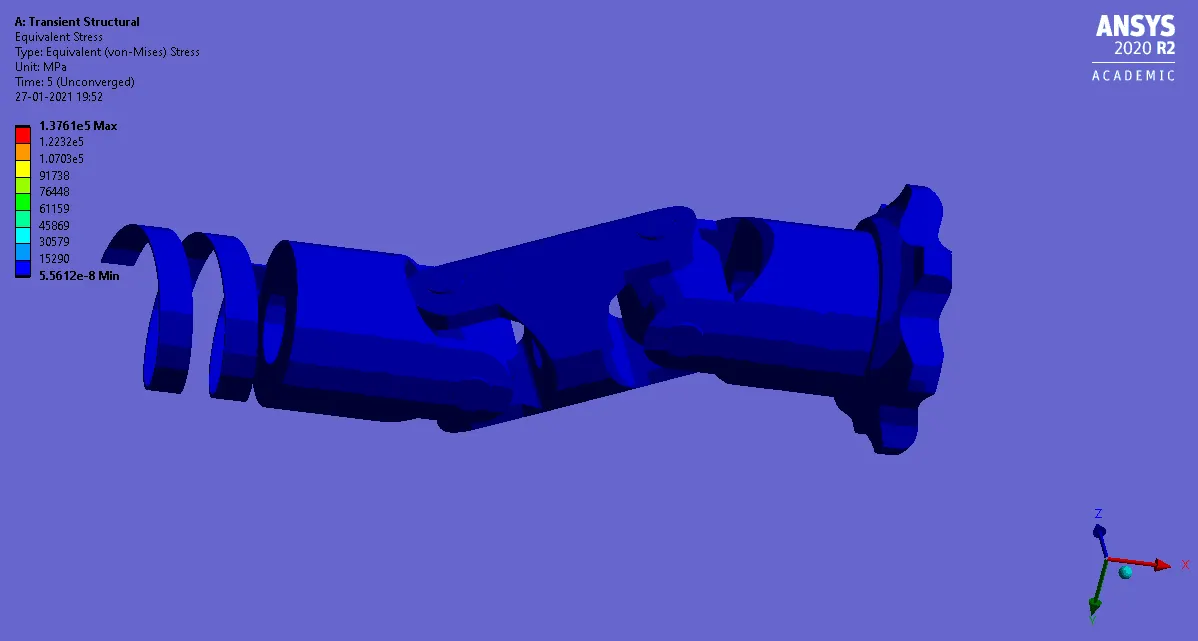
The maximum stress was observed at the joint adjacent to the spring. 1.3761 e+5 MPa and the location of the maximum stress is shown below:
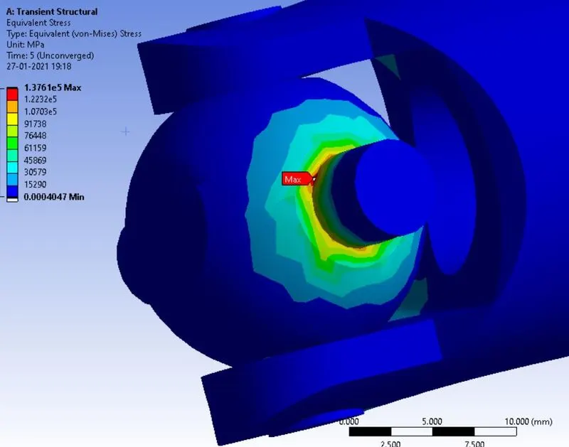
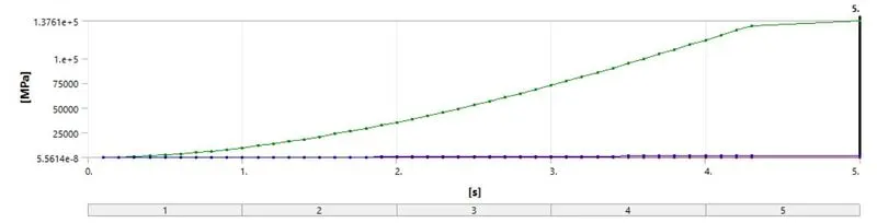
At this region the maximum stress is observed and is the location where the motion transfer takes place due to exertion of force by the spring onto the rest of the assembly as a result of the rotation of the universal joint. The variation of stress with time is shown below:
The deformation contour is shown below:
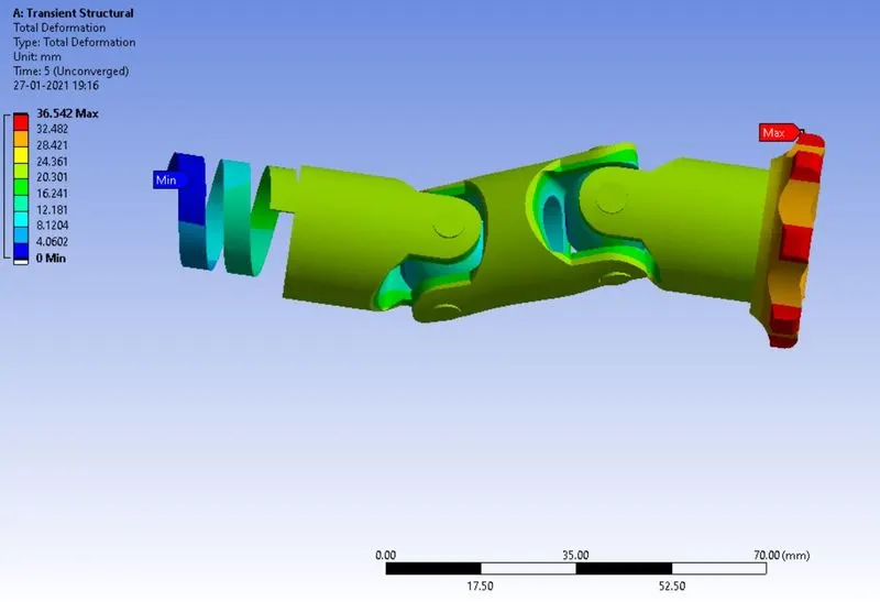
Maximum deformation was observed to be 36.542 mm.
CASE 2: Material = Stainless steel:
The material of the spring and the adjacent joint was changed to stainless steel and the same simulation was solved. The stress contour is given below:
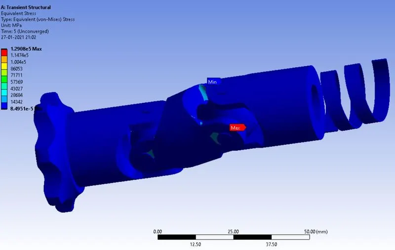
The maximum stress is acting on the joint and the magnitude is 1.2908 e+5 which is lower than the previous case. The region of maximum stress is the same as the previous case and is acting on the joint adjacent to the spring as shown below:
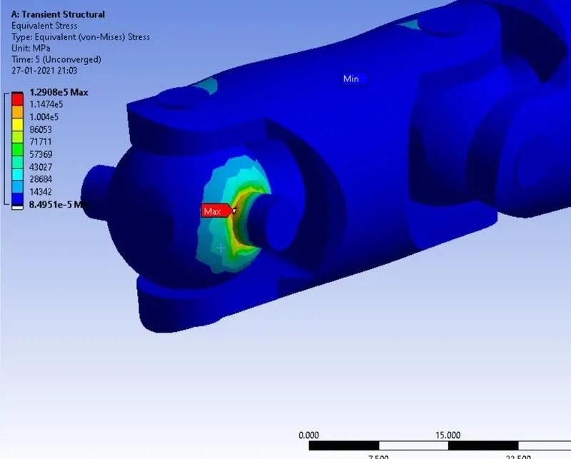
The stress variation with time is plotted below:
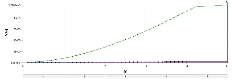
The deformation contour is given below:
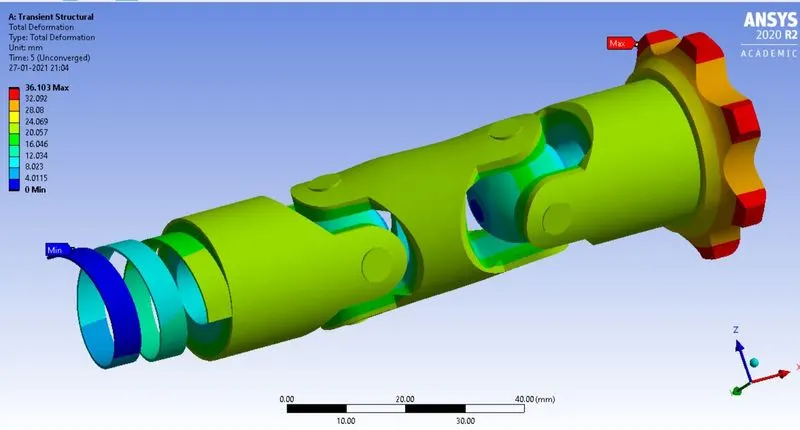
Maximum deformation of 36.103 mm is observed.
Case 3: Material = Titanium Alloy:
The material of the spring and its adjacent joint was changed to Titanium alloy. The simulation was solved and the stress contour is shown below:
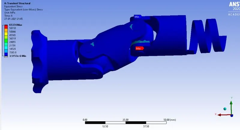
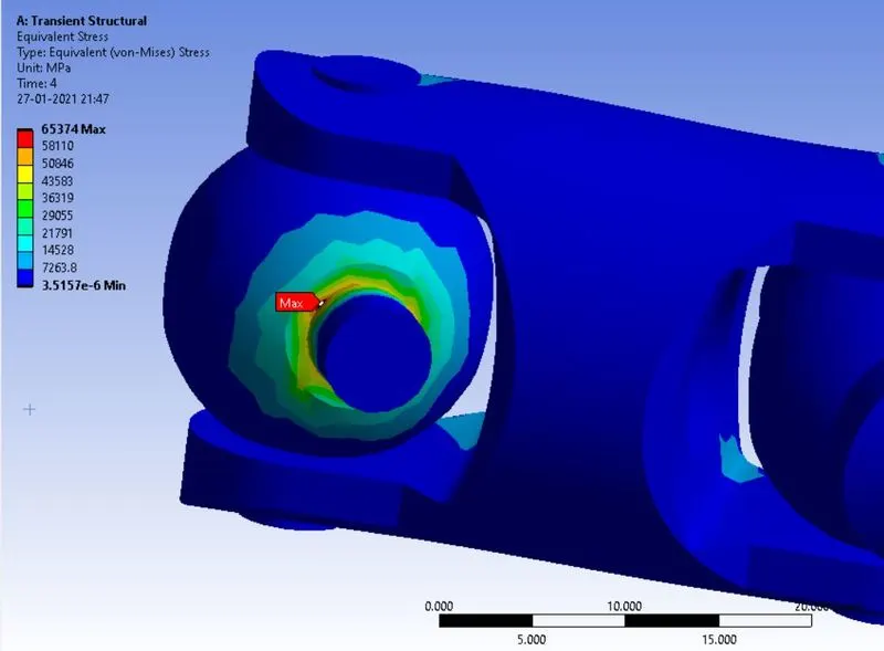
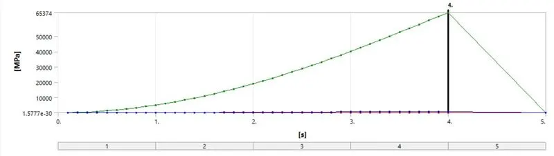
Maximum stress magnitude of 6.5374e+4 MPa was observed and the region of maximum stress remains the same which is the joint adjacent to the spring as shown below:
The stress variation with time is plotted below:
The deformation contour is shown below:
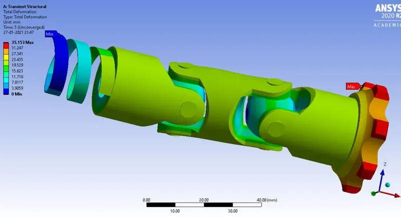
Maximum deformation was observed to be 35.153 mm.
The results from the three cases can be summarized below:
|
Material |
Max Stress |
Max Deformation |
|
Structural Steel |
1.37 e+5 MPa |
36.542 mm |
|
Stainless Steel |
1.29 e+5 MPa |
36.103 mm |
|
Titanium Alloy |
6.53 e+4 MPa |
35.153 mm |
As the material was changed from high stiffness to low stiffness, the stress and deformation both reduced. This can be explained by the fact that the lower stiffness spring imparts lower forces onto the rest of the assembly, therefore the maximum stress observed by the same set of geometry will be lower. This lower stress, therefore, causes deformation to be lower as well.
CONCLUSION: The transient structural analysis of the universal joint with spring was successfully completed and the results were compared and described quantitatively.