2D meshing of various sheet metal components using HYPERMESH
OBJECTIVE: To clean the geometry of the given models and to remove any unnecessary free edge. To extract midsurface and perform geometric cleanup. To create 2D mesh on the midsurface and cleanup elements according to required quality criteria. To assign proper thickness to the mesh.
PROCEDURE:
There were three different models given in this assignment for which meshing operation had to be carried out. The basic steps that have to be followed for these models are as follows:
1. Import geometry into Hypermesh
2. Clean up the geometry and avoid free edges and duplicate surfaces
3. Extract midsurface using appropriate method
4. Perform geometric cleanup on midsurface
5. Perform 2D mesh on midsurface
6. Clean up elements to satisfy given quality criteria
7. Assign thickness values to the mesh
MODEL 1:
The CAD geometry of the first model is given below:
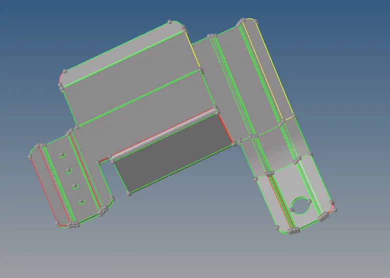
As can be seen from the image, there are several unnecessary free edges and duplicate surfaces that need to be corrected.
The free edges are can corrected by either toggling the edge ( GEOM => quick edit => toggle edge ) or by creating a surface between the two free edges ( GEOM => Surfaces => Ruled ). One example of this being done is given below:
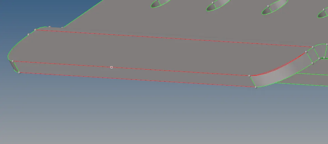


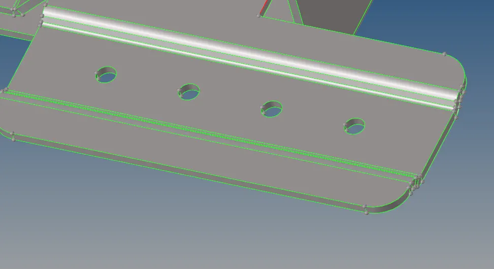
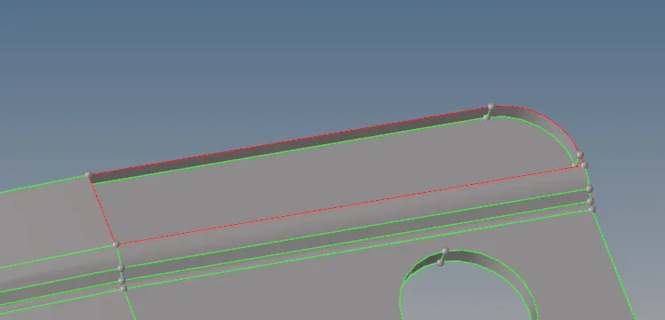
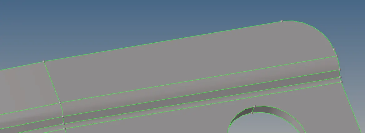
Hence the free edges were corrected. In other regions, duplicate surfaces had to be removed, in other regions surfaces had to be deleted (F2)and restitched to get the proper geometry shape. Some examples are given below:

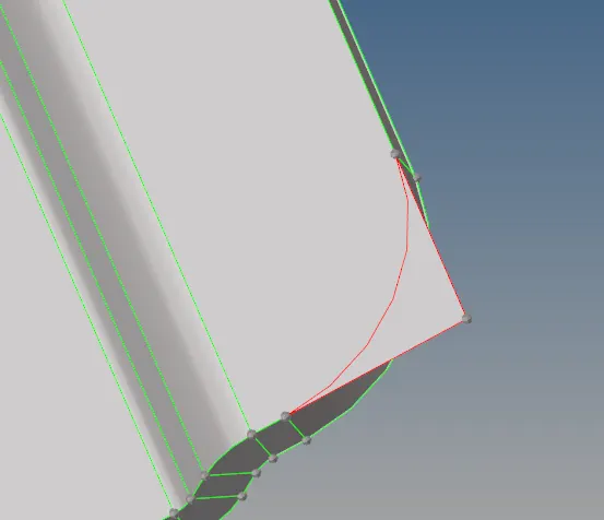


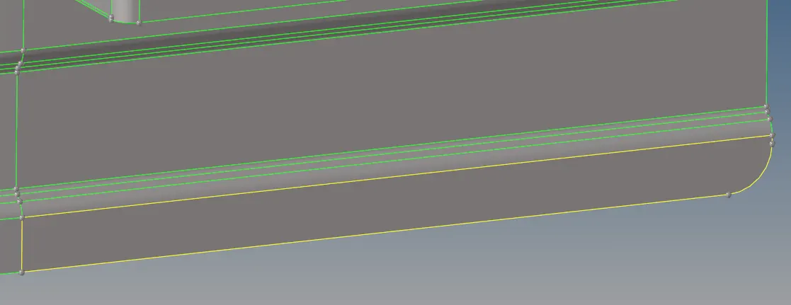
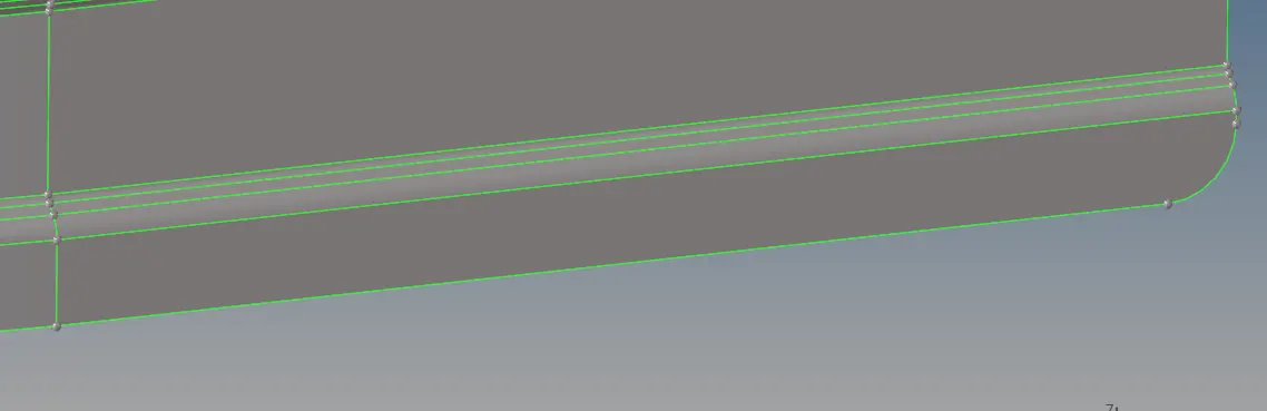
One example of duplicate surface being removed is given below:
Following the geometric cleanup of the geometry, midsurface was extracted by going to GEOM => midsurface => auto midsurface.


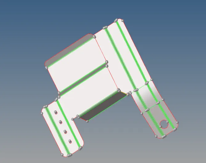
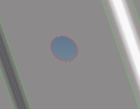
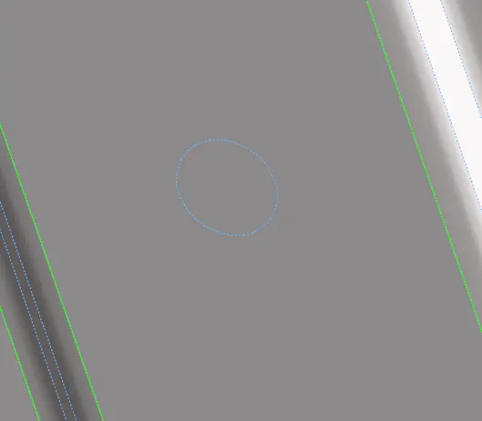
After extraction of midsurface, holes with less than 5mm diameter had to be removed. This can be done at quick edit panel by using filler surf option.
Some edges had to be suppressed in order to meet the minimum element length criteria. This can be done by toggling the surface lines in quick edit panel.
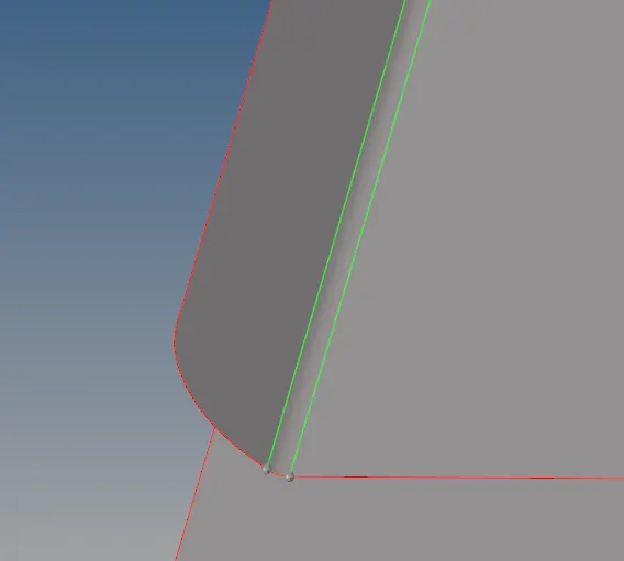
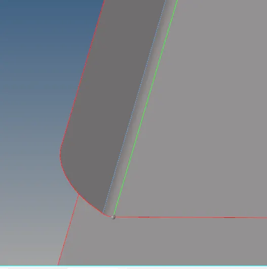
Similarly, other parts of the midsurface were appropriately cleaned prior to meshing to ensure a good mesh flow is achieved and it follows quality criteria.
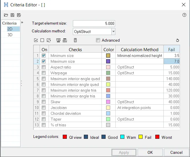
The 2D meshing was done by going to 2D => automesh. The quality criteria was added by going to Preferences => Criteria File Settings.


The initial mesh was obtained and is given below:
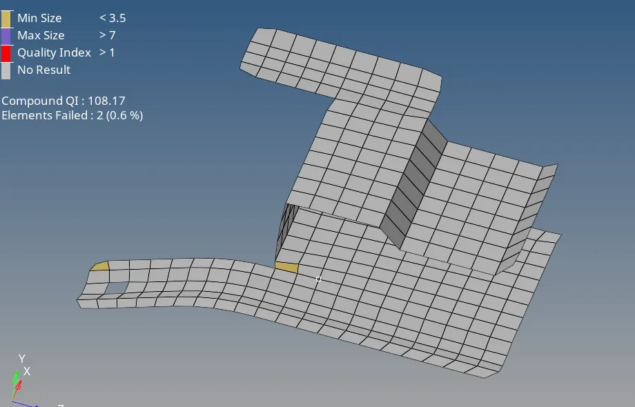
As can be seen from the above figure, two elements are failing for minimum element length. This can be easily solved by going to GEOM => Distance. Select the appropriate nodes and increase distance between them until the element is satisfying the criteria.

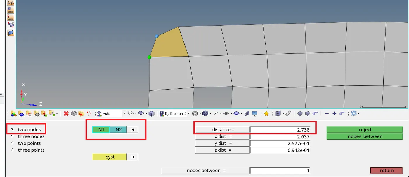
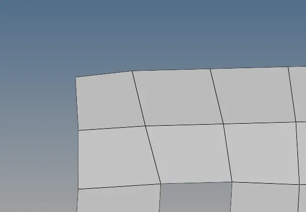
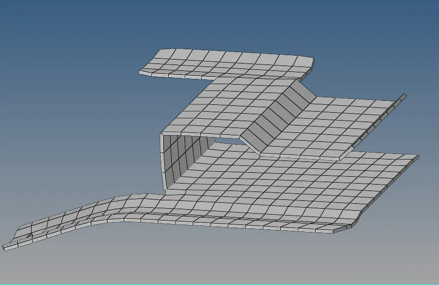
Hence the final mesh was obtained. To assign thickness, a new property was added which was assigned the thickness. This property was then assigned to the mesh. The below figure shows the detailed representation of the mesh after thickness was assigned:
A comparison of the mesh and the geometry can be seen below:
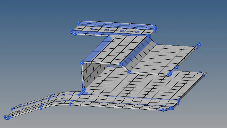
The blue colour indicates the initial geometry. It is apparent that the feature capturing is not good at the fillets and other curved surfaces. This is necessary in order to maintain the minimum element length and hence feature capturing at certain regions had to be sacrificed as a trade-off.
MODEL 2:
The CAD geometry of the second model is given below:
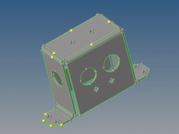
As can be seen, there are no free edges or duplicate surfaces visible on the geometry. The temporary nodes were cleared out by going to GEOM => temp nodes. The next step is to extract the midsurface. The procedure for extraction of midsurface is already given in model 1. The only difference here is that in extraction options, "Skin Offset" was given instead of "Offset + places + sweeps". The midsurface is shown below:
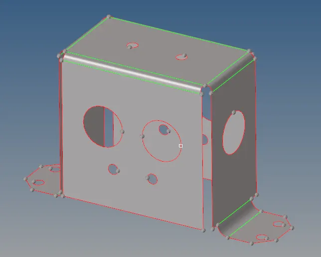
The holes are equal to or greater than 5 mm and hence cannot be ignored. The geometric cleanup was not required for this and meshing was done on the midsurface similar to model 1.
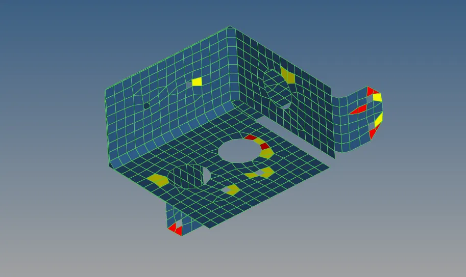
As can be seen from the initial mesh, the elements are failing for quality at multiple places. This can be easily solved by going to 2D => qualityindex => cleanup tools. The "Element optimize" is a very useful tool which can be used to clean up the elements to adhere to the given quality parameters.


Using the clean up tools, the mesh is optimized to adhere to the quality criteria.
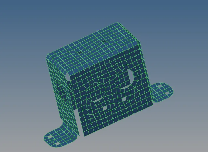
As can be seen from the final mesh, no element is failing. Thickness is added to the mesh by assigning property to the mesh. The mesh is then compared to the original geometry in the below figure:
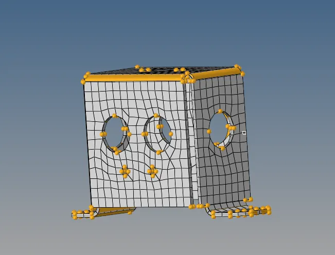
The orange is the original geometry. As can be seen from the figure, the fillets are not properly captured. In order to capture them effectively, more elements have to be given at the fillets. However, this will lead to failure for minimum element length. Hence, some feature capturing has to be sacrificed.
MODEL 3:
The CAD geometry of the third model is given below:
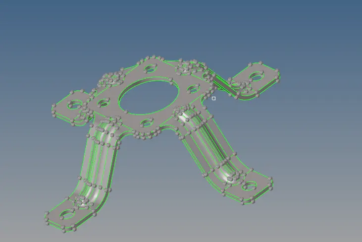
This model has no free edges or duplicate surfaces and hence we can proceed to extraction of midsurface. The midsurface was extracted similar to model 2 with skin offset method in automidsurface.
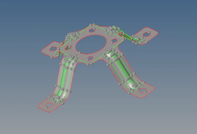
Some surface lines had to be toggled off in order to not fail for minimum element length. The 2D meshing was done and initial mesh is given below:
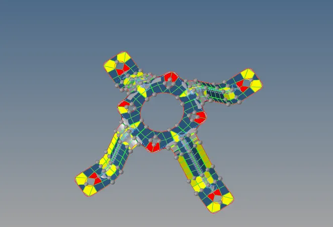
As can be seen, many elements are failing quality criteria. They are cleaned up using the tools as in model 1 and model 2.
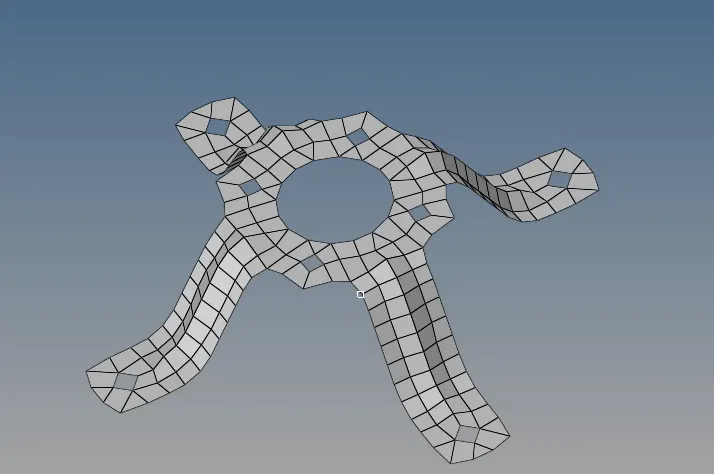
Hence the final mesh is obtained which adheres to the quality crtieria.
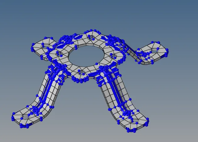
Comparison to the original geometry (Dark Blue colour) is seen in the above figure after thickness is assigned to the mesh. Again, feature capturing at curved surfaces had to be sacrificed in order to maintain quality parameters.
CONCLUSION: The three models were cleaned up geometrically and the midsurfaces were successfully extracted. The midsurfaces were also geometrically cleaned and meshed with 2D elements. The elements were then cleaned up to adhere to the given quality parameters. The mesh was then assigned with appropriate thickness values.