RADIOSS PROJECT 2: Side-crash analysis of NEON dodge model using HYPERMESH and RADIOSS
OBJECTIVE: To perform a side-crash test on a Neon Dodge model with reduced BIW components against a rigid pole. To compare the resultant forces acting upon cross-sections of critical components as well as intrusions and velocities of critical points in the car.
PROCEDURE: To complete the analysis of a side-crash, the following steps have to be followed:
1. Import the reduced BIW model into Hypermesh / Hypercrash
2. Add masses at appropriate locations in order to simulate the testing of a full model in terms of weight
3. Assign contact interface (Type 7)
4. Check for penetrations and connectivity
5. Add initial velocity to the model
6. Create the rigid pole
7. Add appropriate time step to the simulation
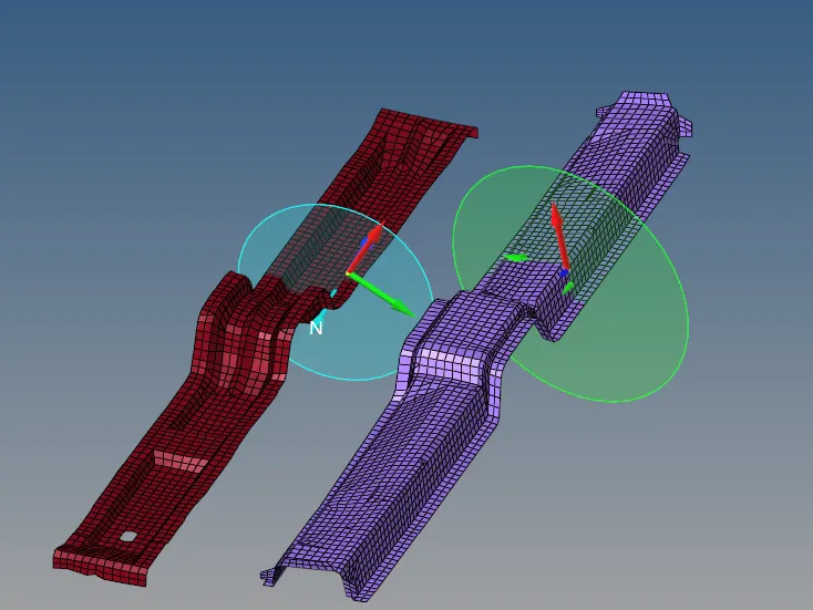
8. Create sections at cross members and create output blocks for normal and tangential forces at these sections
9. Detect displacements occurring at critical regions such as hinge pillar, fuel tank and B-pillar by generating nodal output blocks
10. Detect velocity experienced by car door by generating appropriate output block
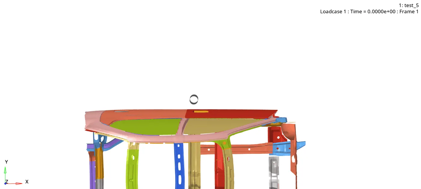
Initially, the reduced BIW model was imported onto Hypercrash and is shown below. The unit system is [kg mm ms]:
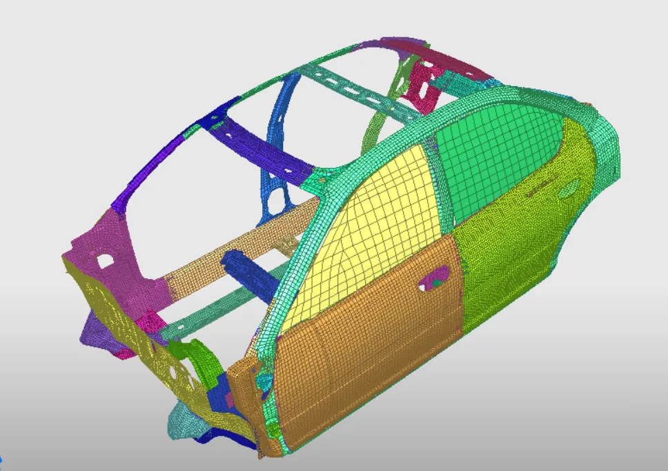
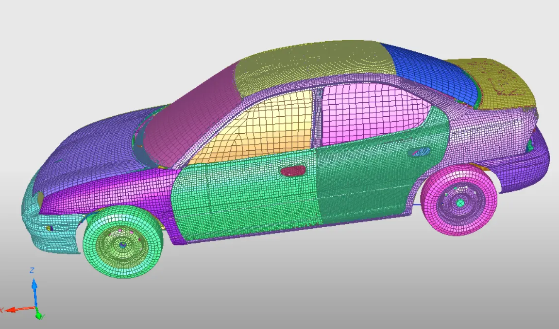
The area with the side doors is the part that is going to impact upon the rigid pillar. The full model would look like the below image:
MASS ADDITION:
In order to improve the accuracy of the reduced BIW model, the mass of the reduced model has to be similar to that of the full model as well as the centre of gravity being in a similar position as that of the full model. This will ensure that the kinetic energy experienced by the model while in motion is realistic. The initial mass and center of gravity are shown below:
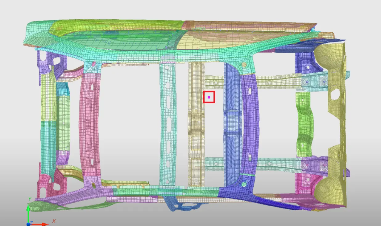

The mass of the full model is assumed to be 700 kg and the center of gravity aligns approximately at the center of the cross member (Yellow colour). In order to simulate this condition, mass was strategically added to the frames of the reduced BIW model by going to the Browser and double clicking on Added Mass. In Added Mass tab, create new added mass. The results are shown below:
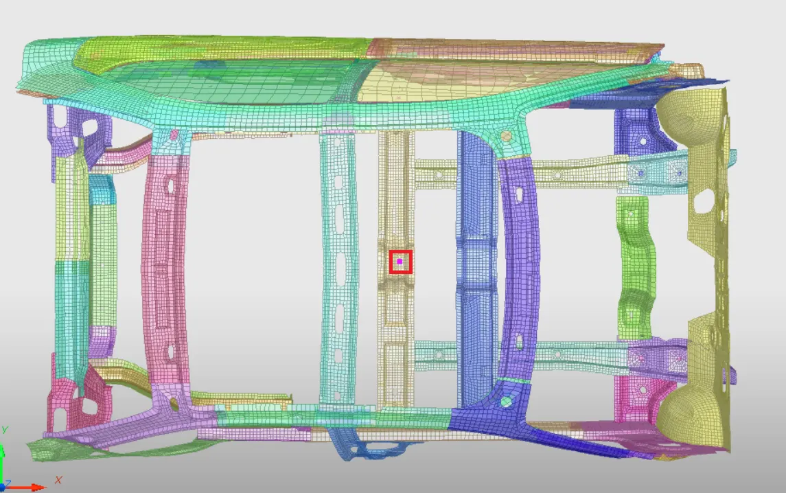
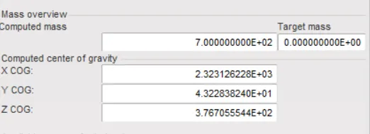
As can be seen, the mass was added until final mass of 700 kg was obtained. The center of gravity is also in a more realistic location as described in the paragraphs above. This ensures that the masses of the reduced model behave in a more realistic way.
CONTACT INTERFACE:
Contact interfaces are a crucial step and dictate the manner in which various components behave when they impact forces upon one another. In the present simulation, contact Type 7 was implemented. This was done because contact type 7 is the most commonly used and is a very general type of contact. It is a node to surface contact type in which the surfaces act as master and nodes act as slaves. The properties were given to the interface in accordance with the recommendations for crash analysis and are given below:
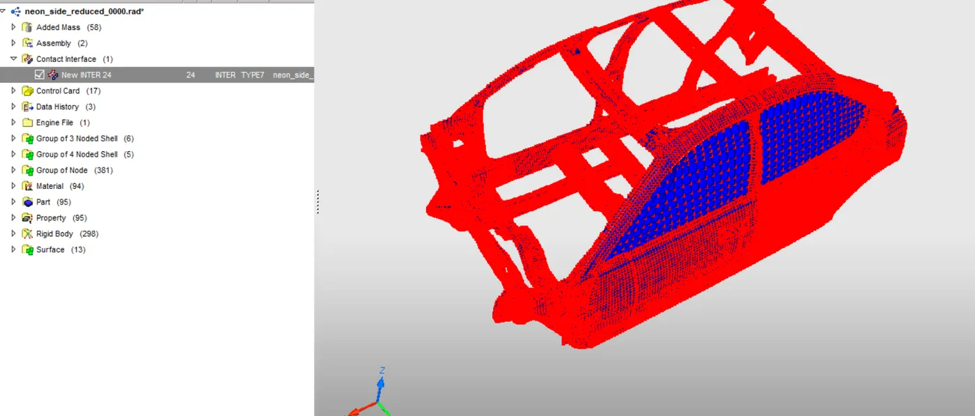
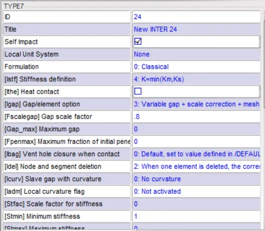
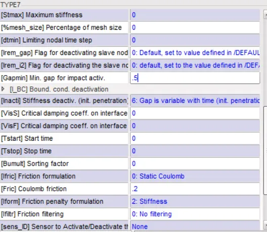
The redundant interfaces were deleted. To add contact interface, go to Loadcase => Contact Interface. Create a type 7 interface and add the recommended properties to it.
Following the addition of contact interfaces, penetration check was done on the model. No penetrations were found.
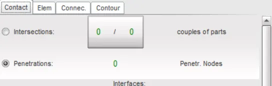
However, a few components were not connected and this was corrected by going to Hypermesh and adding rigid elements to connect the components.
INITIAL VELOCITY:
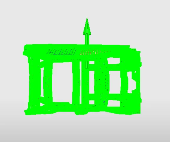
An initial velocity of 35 miles per hour was added to the model. Upon conversion, this goes to 15.6464 mm/ms. The velocity was given in y-direction because this is the direction in which the model will impact upon the rigid pole. The velocity can be added by going to Load case => Initial velocity.
RIGID WALL:
In order to create a rigid wall, go to Load Case => Rigid Wall. For the purpose of the present simulation, a cylindrical rigid wall was created with the axis of the cylinder being parallel to z-axis.
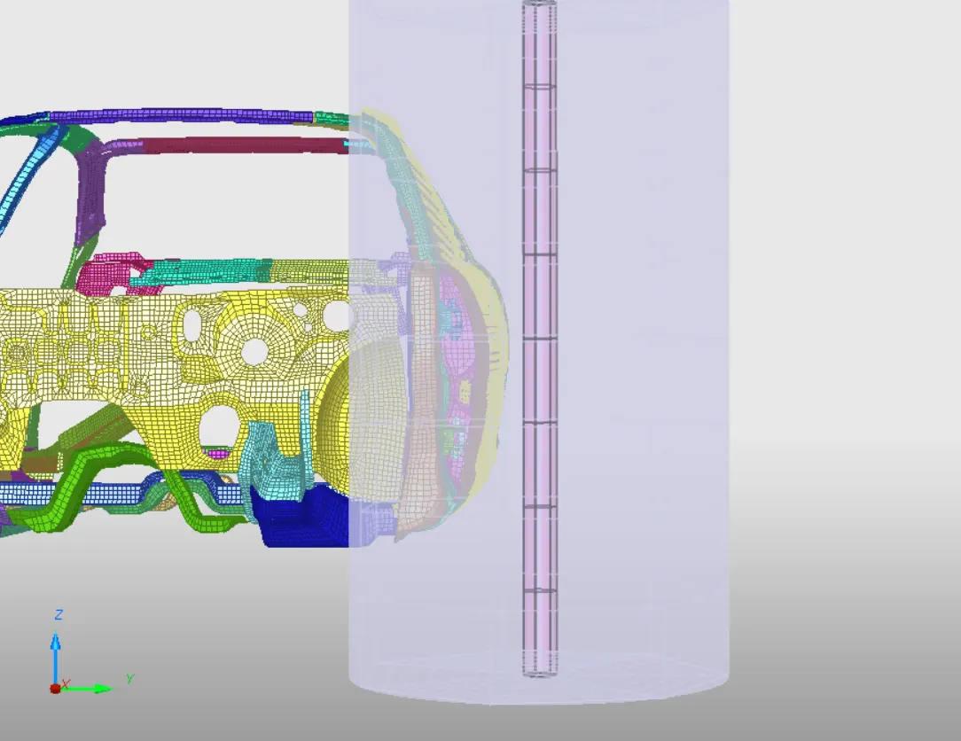
Friction of 0.1 was given to the rigid wall.
MODEL CHECKER:
The model has to be checked for any errors or warnings which might affect the validity of the results. This can be done in Hypercrash by going to Quality => Model Checker => Run.
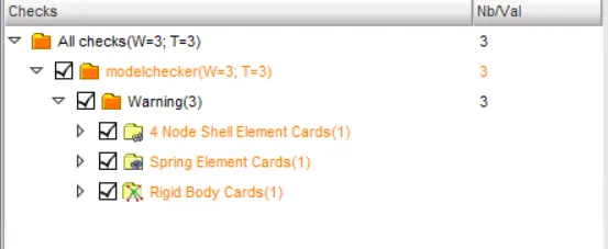
The following warnings were shown initially:
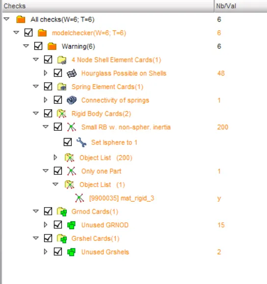
After fixing some of the warnings, the following warnings were displayed, which can be ignored:
TIME STEP:
Time steps can be given by going to Hypermesh and selecting Tools => Engine File Assistant. Nodel time step of 0.5 microseconds was selected and simulation run time was given as 80 ms.
OUTPUT BLOCKS:
Apart from the default outputs that the Hypermesh simulation provides, additional output blocks are required to check the forces, displacements and velocities that are imparted upon a few critical regions. For the present simulation, sections were created on cross members to check the axial and tangential forces acting upon their cross-sections. Also, displacements occurring on Hinge pillar, B-pillar and fuel tank need to be observed and therefore, appropriate nodal output blocks were created for them. The velocity of the car door needs to be calculated and nodal output block was created to detect this as well.
To create a section, go to Solver browser in Hypermesh, and right-click and go to Create => Sect => Sect_Circle. Select the elements, nodes, orientation and radius appropriately and create the section. To create output block, go to TH => Create => Sectio. Select the sections and add the required outputs i.e Normal forces and Tangential forces.
To detect intrusions, first create a moving skew on the opposite end of the car. This creates a frame of reference. The create a nodal output by going to TH => Create => Nodes. Select the node and select the skew frame and give Displacement or velocity as output as required.
RESULTS:
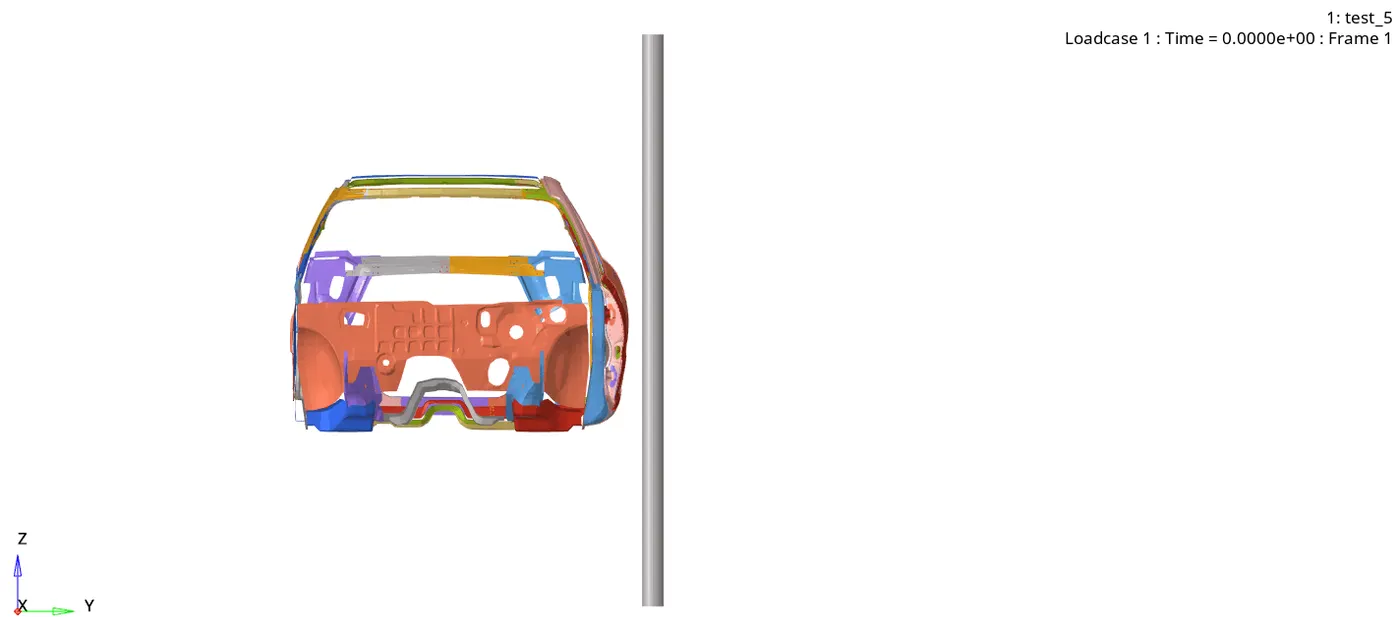
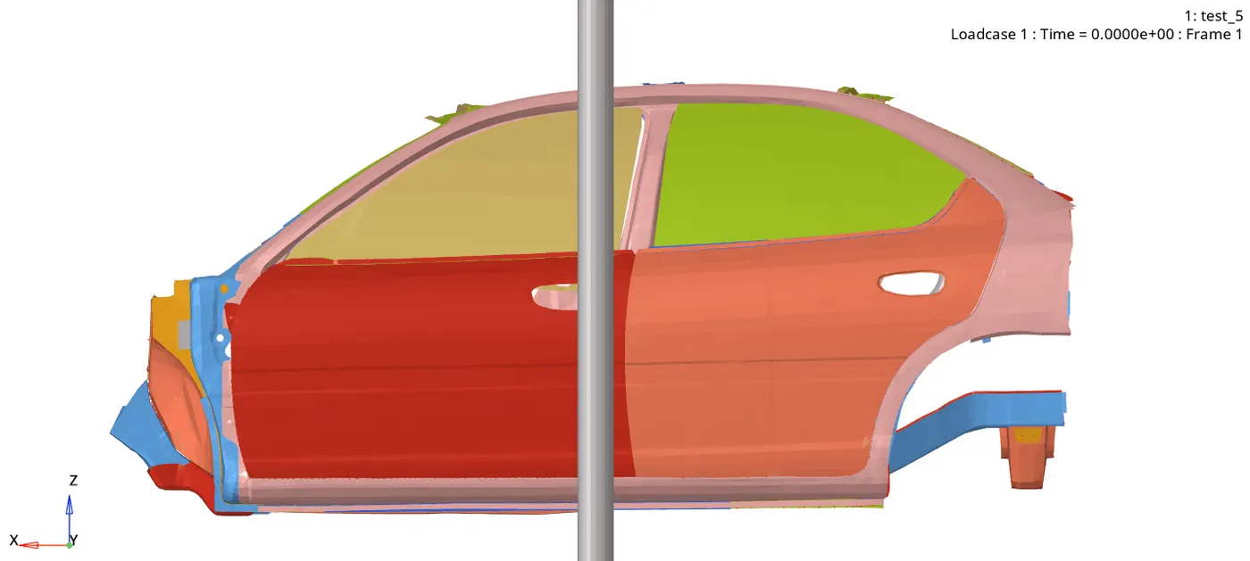
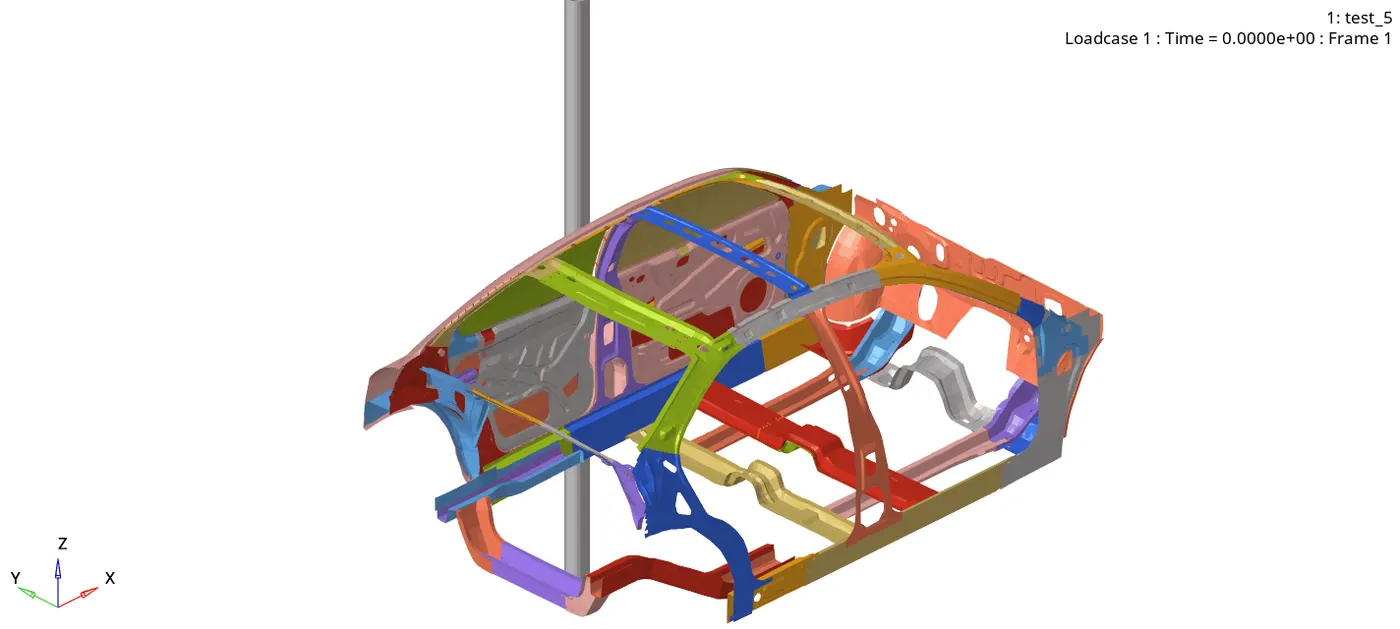
The simulation run time was 7496.77 s. Maximum energy error was -5.1% and maximum mass error was 0.4376 E-04. These values are within the limits for accurate results. The crash results are shown below for various orientations:
VON-MISES STRESS:
The stress upon impact needs to be distributed along the various frames of the car. Below is the variation of stress upon impact:
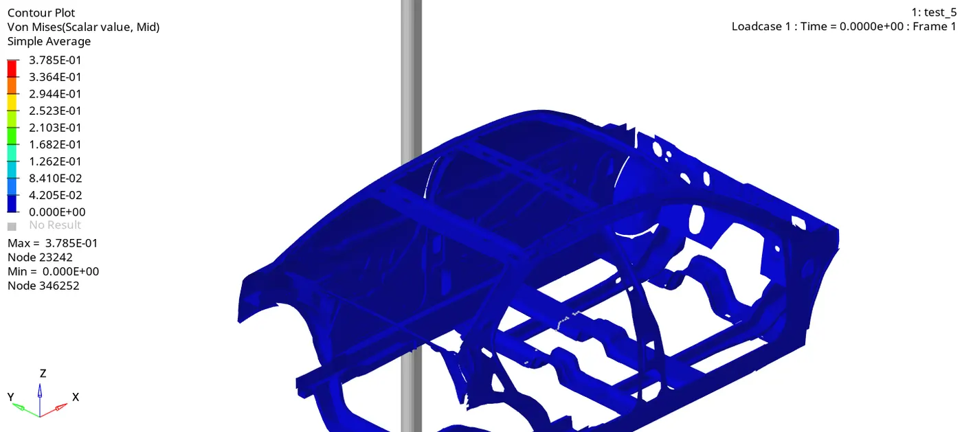
As can be seen, the maximum Von-Mises stress of 0.3785 MPa is reached. The flow of stresses is seen which indicates a good design. Forces acting upon the various crucial members of the car need to be checked as well.
CROSS MEMBERS:
The normal and tangential forces acting upon the cross-section of the two cross members are plotted below:
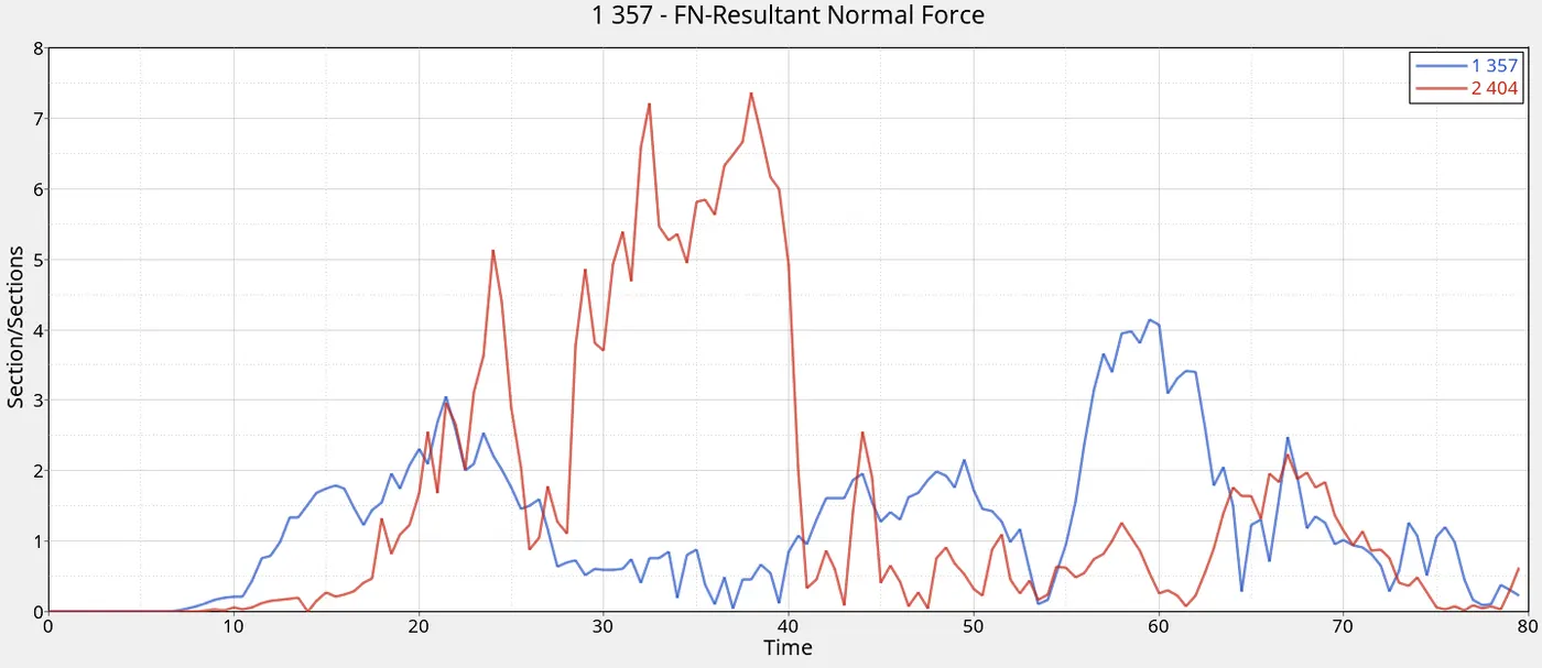
The blue curve is for frontal cross member and the red curve is for the rear cross member. The frontal cross member has a maximum normal force of 4.137 KN whereas the rear member has 7.363 KN.
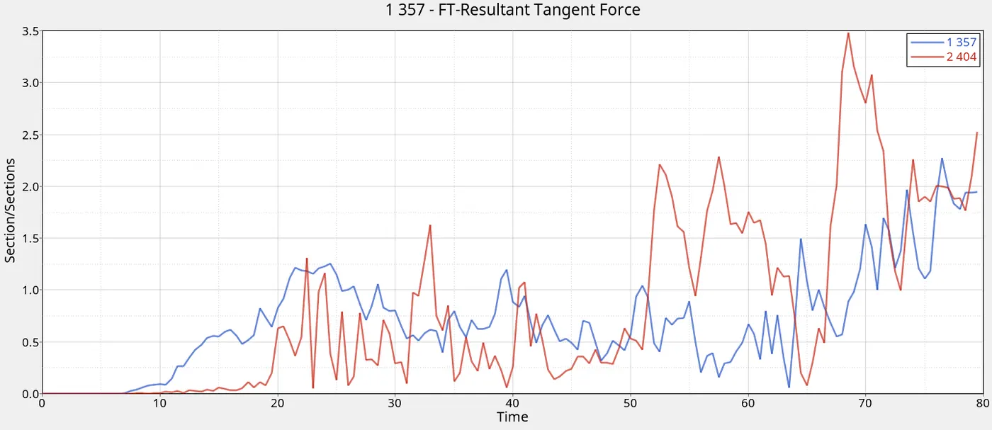
The frontal member has a maximum tangential force of 2.269 KN and the rear member has 3.476 KN.
Therefore, it can be seen that in both cases, the rear cross member experiences more force and therefore has to be more sturdy in design. Also, btih cross members experience more normal force than tangential force and therefore, normal forces have to be prioritized.
INTRUSIONS:
The displacements occurring on the hinge pillar, fuel tank and B-pillar were detected and are plotted below:
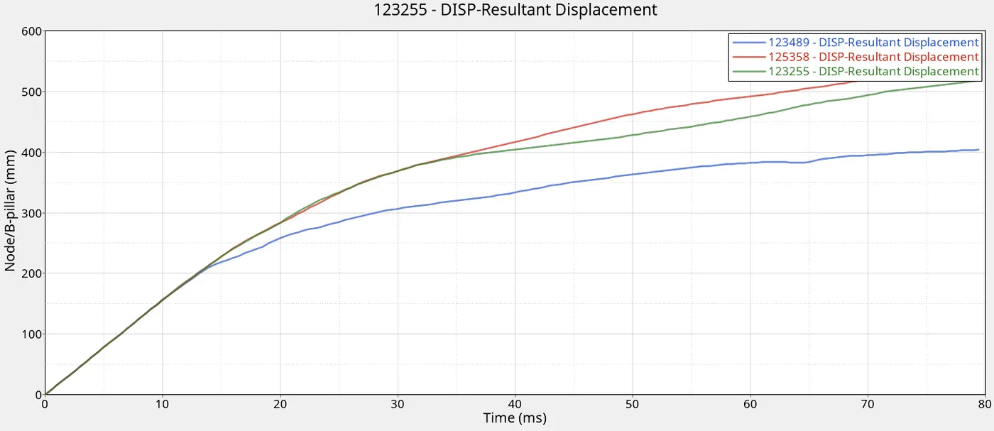
The blue curve is for B-Pillar, red curve is for fuel tank and green curve is for Hinge pillar. As can be seen from the graph, the fuel tank experiences the highest intrusion whereas the B-pillar experiences lowest intrusion. This is a good design as fuel tank can be reinforced further whereas B-pillar which is next to the passengers/ driver needs to displace as less as possible to avoid significant injuries. The fuel tank has maximum displacement of 537.441 mm, hinge pillar has 517.791 mm and B-pillar has 403.426 mm.
The velocity variation experienced by the car door with respect to various axes are plotted below.
X-Axis:
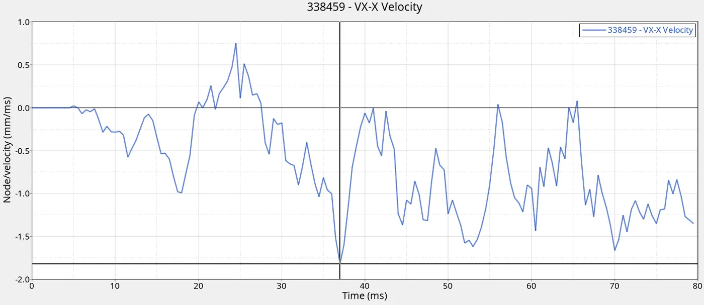
Maximum velocity of 1.815 m/s is reached in x-axis.
Y-Axis:
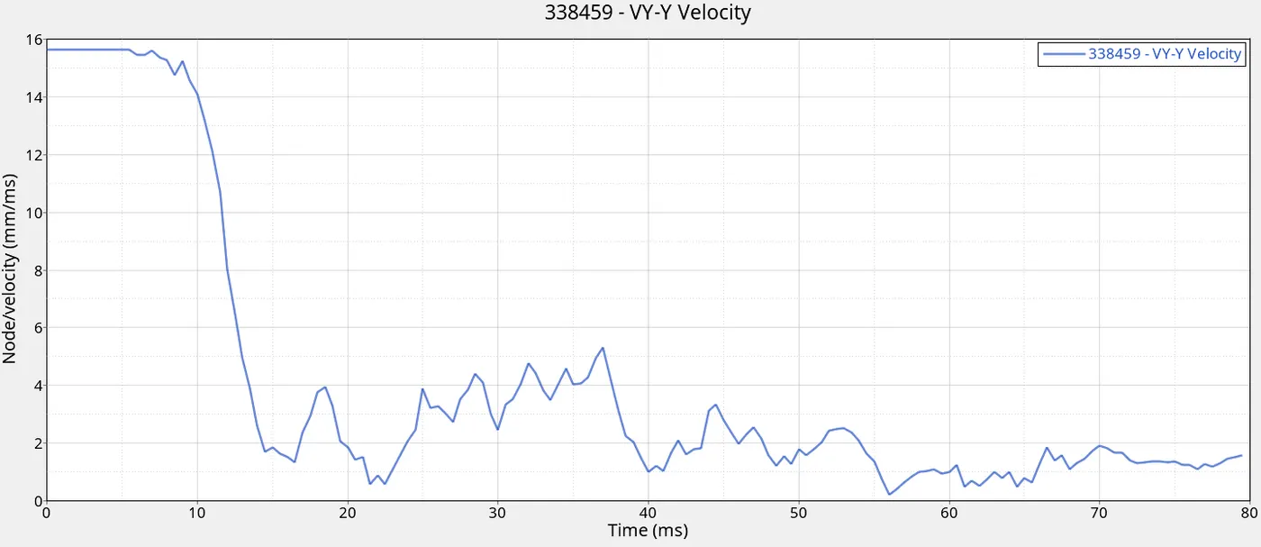
Y-axis is the axis of propagation of the car. A maximum of 15.6464 m/s is achieved. Upon impact, the velocity decreases drastically.
Z-axis:
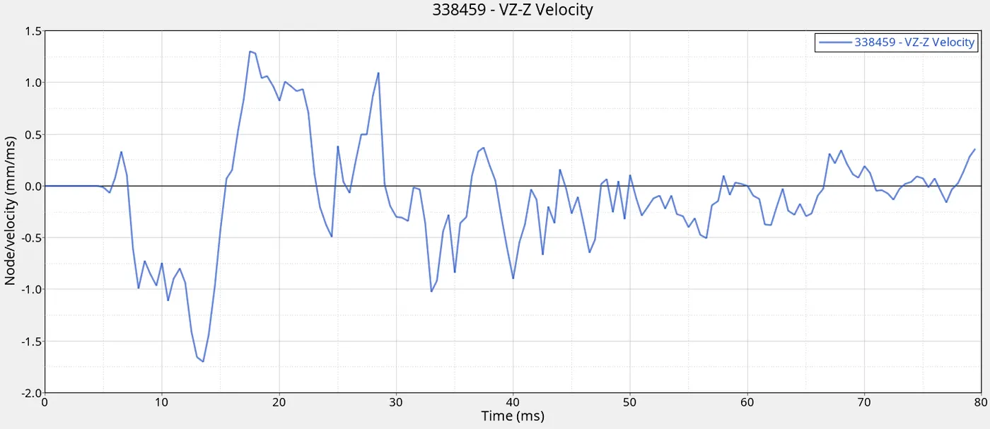
A maximum velocity of 1.7 m/s is reached in the z-direction.
ENERGIES:
The internal and kinetic energies are plotted below:
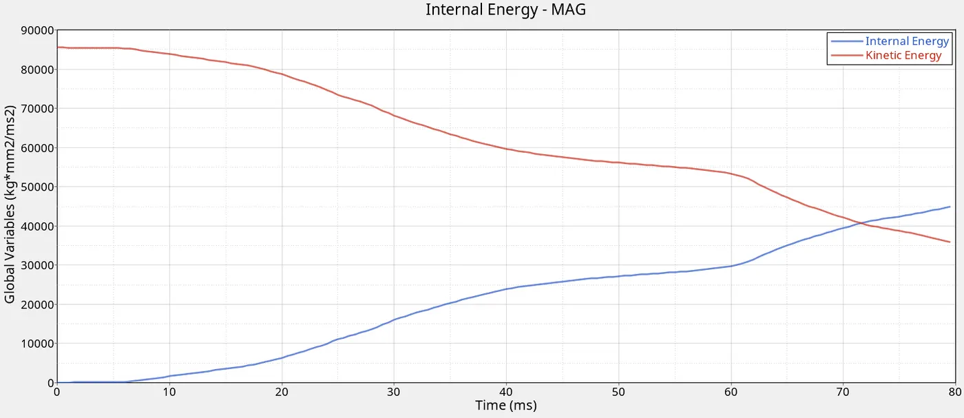
As is expected, the kinetic energy is at its peak initially and upon crash, it loses velocity and hence the kinetic energy increases. The internal energy increases upon impact as the material absorbs energy and keeps increasing with time.
MASS:
Masses are increased when time step goes below minimum time step value. When time step goes below minimum value, the mass is added to the model to increase the time step above the minimum value. If this added mass is high, then it can impact on the validity of the results because it changes the value of kinetic energy. The mass variation with time was plotted below:
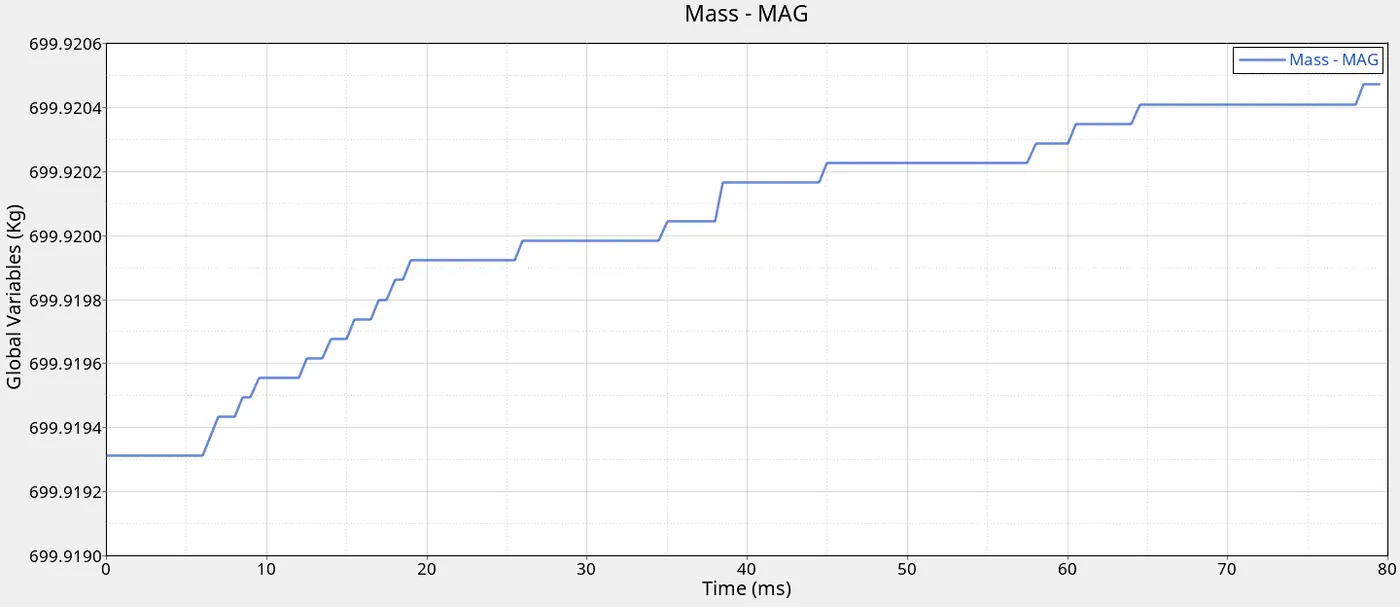
As can be seen, the added mass is very low relative to the initial mass and hence, the results are valid.
The results can be summarized with the table below:
|
Parameter |
Values |
|
Runtime |
7496.77 s |
|
Max hourglass energy |
383.2 J |
|
Max plastic strain |
1.141 |
|
Max von mises stress |
0.3785 MPa |
|
Max energy error |
-5.1% |
|
Max mass error |
0.4376 E-04 |
|
Initial Kinetic energy |
0.855 E+05 J |
|
Final Kinetic Energy |
0.3562 E+05 J |
|
Final Internal Energy |
0.4519 E+05 J |
|
Max rigid wall force |
203.197 KN |
|
Max normal force at frontal cross member |
4.137 KN |
|
Max normal force at rear cross member |
7.363 KN |
|
Max tangential force at frontal cross member |
2.269 KN |
|
Max tangential force at rear cross member |
3.476 KN |
|
Max car door velocity y-axis |
15.6464 m/s |
|
Max car door velocity x-axis |
-1.815 m/s |
|
Max car door velocity z-axis |
-1/7006 m/s |
|
Max B-pillar displacement |
403.426 mm |
|
Max fuel tank displacement |
537.441 mm |
|
Max hinge pillar displacement |
517.791 mm |
Potential improvements to simulation:
1. Change material formulation from reduced integration to full integration
2. Change contact interface to more robust one which can handle all forms of interactions
3. Finer meshing in critical areas
4. Change fracture modelling of glass to include brittle fracture
5. Simulate full model instead of reduced BIW model
6. Increase integration points in elements and across thickness
CONCLUSION: The side-crash simulation was successfully completed and the results were discussed in depth. Few points were made as to how the simulation can be further improved.