Drop test of a phone using LS-DYNA
AIM: To simulate the drop test of a phone onto the floor using LS-Prepost and LS-DYNA.
PROCEDURE: To simulate a drop test of a phone the following steps were followed:
1. Import the meshed keyword file into LS-Prepost:
The drop test model was imported into LS-PrePost and is shown below:
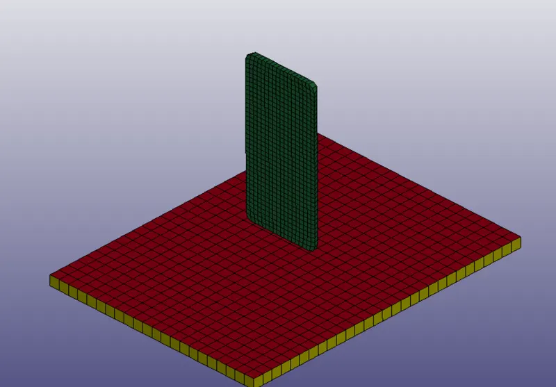
The green solid element part is the phone. The red and yellow parts are the shell and solid floors respectively. The unit system [kg mm ms] was used for the current simulation.
2. Apply material and section properties:
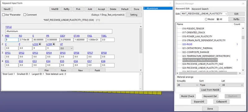
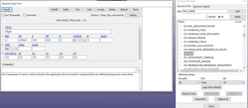
The phone is assumed to be made out of an aluminium frame and linear plastic material and is comprised of solid elements. The floor is assumed to be rigid steel material with shell and solid elements respectively. Materials can be defined in LS Prepost by going to Model and Part => Keyword Manager => MAT.
The phone material was Type024_Piecewise_Linear_Plasticity with density of 2710 kg/`m^3` , young's modulus of 80 GPa, and other generic Aluminium properties as shown below:
The floor was assumed to be made of rigid steel and was designated the Type020_Rigid material and defined as given below:
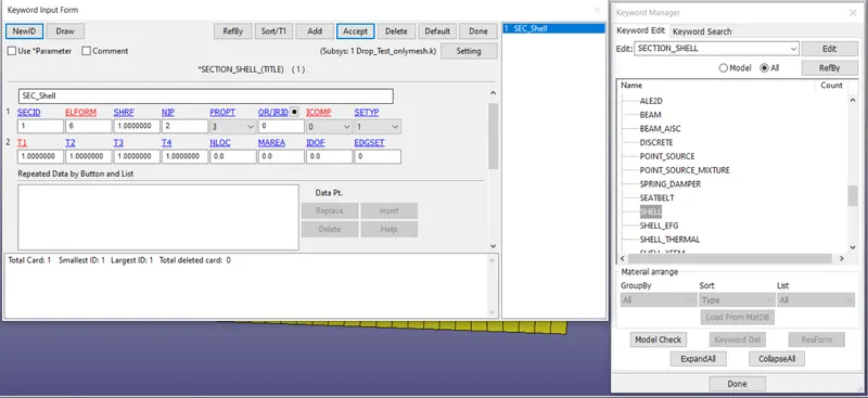
Sections for shell and solids were assigned by going to Model and Part => Keyword manager => SECTION.
For shell section, Elform = 6 was chosen with a thickness of 1mm and was assigned as shown below:
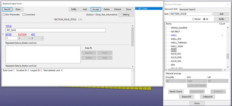
The solid section had ELFORM = 1 and assigned as shown below:
3. Define contact:
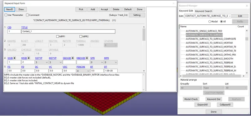
For the present simulation, Surface-to-Surface contact was selected with floor as master surface and phone as salve surface. Contact was defined in Keyword manager by going to Contact => Automatic_surface_to_surface as shown below:
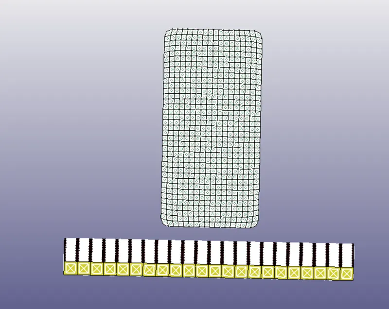
The phone surfaces were the slave and rigid floor surfaces were the master.
4. Define boundary conditions:
Boundary conditions can be defined in LS-PrePost by going to Keyword manager and going to Boundary => SPC_Set. For the rigid floor, all six degrees of freedom were restricted. For the phone, only the translation about the z-axis was allowed as shown below:
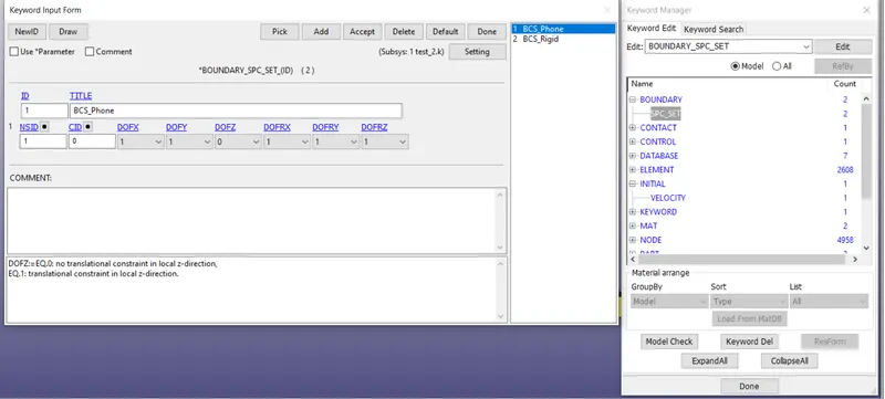
BCS for Phone
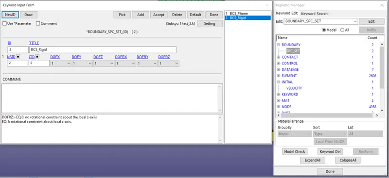
BCS for Rigid Floor
5. Define Initial velocity for Phone:
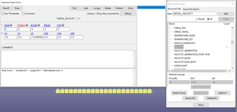
The phone has to travel in negative z-axis to impact upon the floor. A velocity of 10 m/s was given to the phone. Initial velocity can be defined in keyword manager by going to Initial => Velocity as shown below:
6. Define control cards and output blocks:
For the present simulation, termination card is sufficient. A termination time of 30 ms was selected arbitrarily. This can be done in Keyword manager by going to Control => Termination and giving EndTime as 30 ms.
To define output blocks, go to DATABASE in Keyword manager. Several outputs such as GLSTAT, MATSUM, RCFORC and RWFORC can be requested in ASCII with frequency of 0.1 ms. Binary_D3PLOT and BINARY_D3THDT were also requested.
RESULTS:
The von mises stress contour at point of contact is shown below:
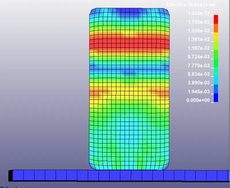
The highest stress at point of impact is shown to be 19 MPa and is indicated by the red region on the phone.
The point of maximum stress is at 0.3 ms from impact where the stress reaches up to 27 MPa and is indicated by the red region below:
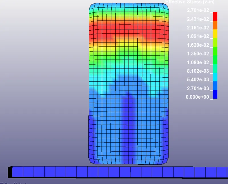
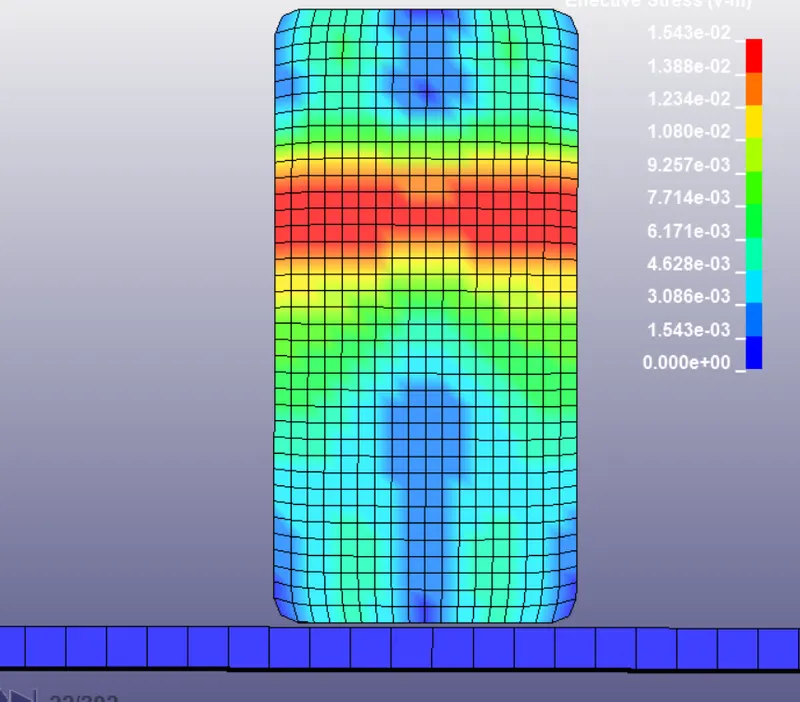
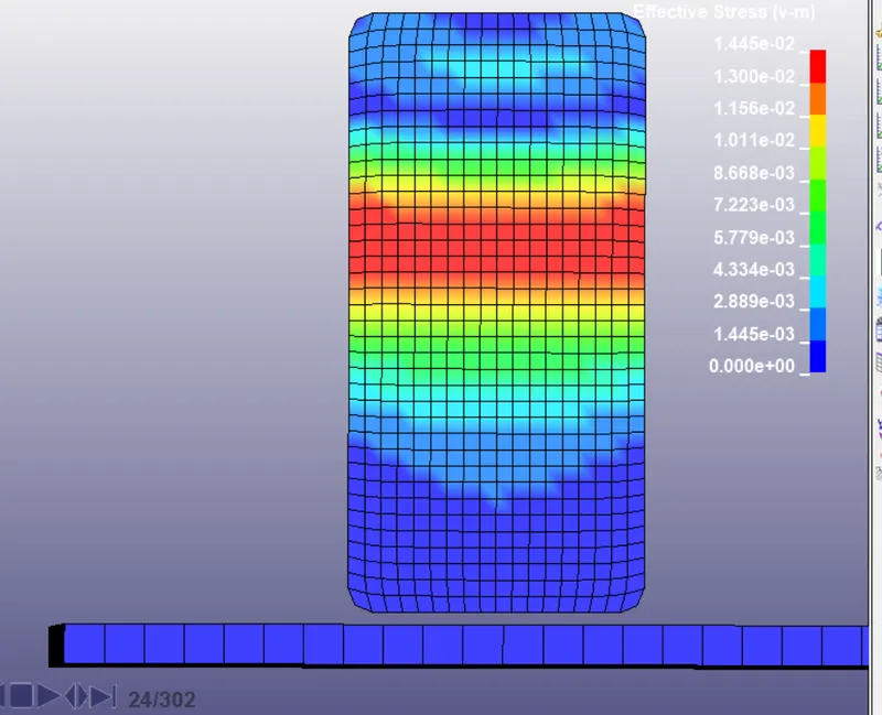
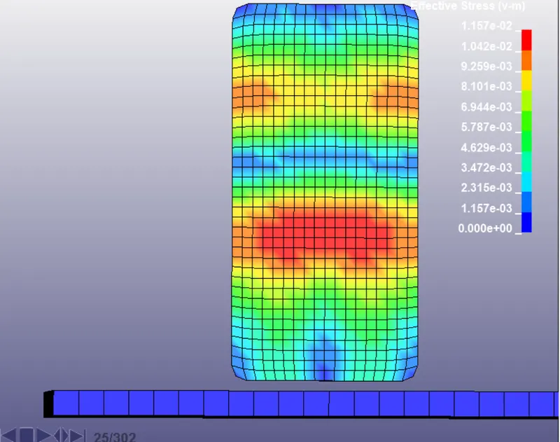
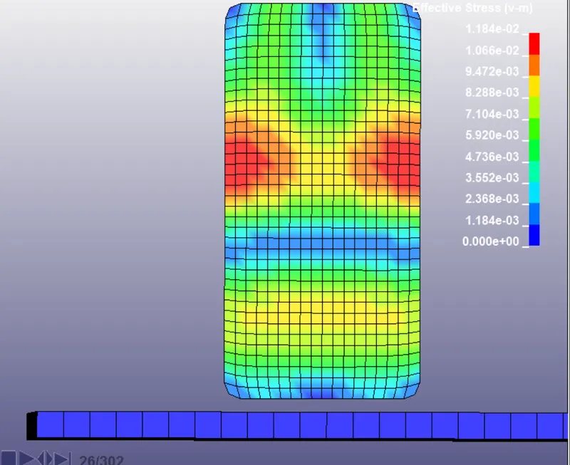
As can be noticed from the images, the stress distribution changes with time and is not constant. A wave-like propagation of stress is seen as shown below:
The Kinetic and Internal energies are given below with Energies as y-axis and time as x-axis:
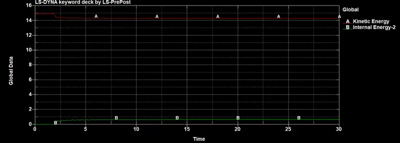
As can be seen, the internal energy is zero at the beginning and increases at the time of impact which results in a reduction of kinetic energy. After the impact, both energies are constant.
The force variation with time is given below with force as y-axis and time as x-axis:
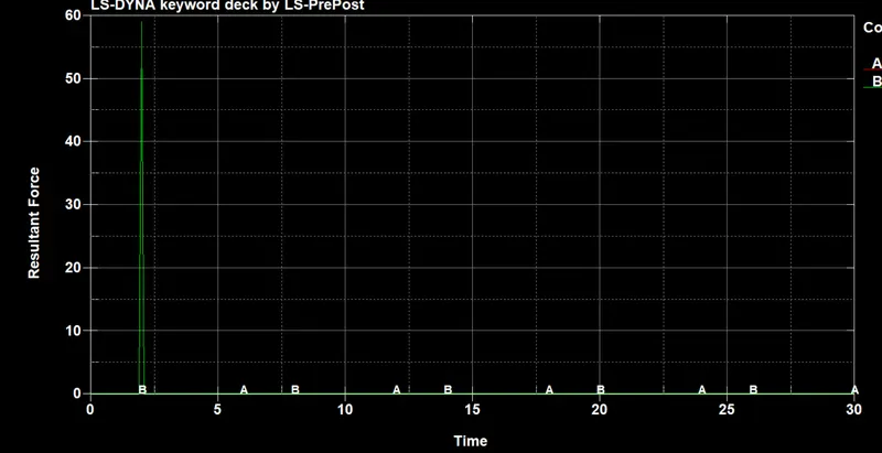
As can be seen from the graph, force has a delta-like peak at the point of impact with a maximum of around 60 KN.
CONCLUSION: The phone drop test was successfully completed with addition of all relevant keywords. The output results were discussed.