SIMULINK MODEL - DOOR BELL CIRCUIT & TEMPERATURE SENSING FAN
AIM :
To make the required simulink models and simulate them to study the results.
OBJECTIVE :
To make a Simulink model of Doorbell using solenoid block.
To use a thermistor to sense the temperature of a heater & turn on or turn off the fan.
STUDY 1 : Simulation of a doorbell
Solenoid :
A solenoid is a device comprised of a coil of wire, the housing and a moveable plunger (armature). When an electrical current is introduced, a magnetic field forms around the coil which draws the plunger in. More simply, a solenoid converts electrical energy into mechanical work.
It is a very important coil of wire that is used in inductors, electromagnets, antennas, valves, and many more. The application of a solenoid varies in many different types of industries. It can be used in a simple locking device, medical clamping equipment, an automotive gear box, and an air conditioning unit.
Circuit :
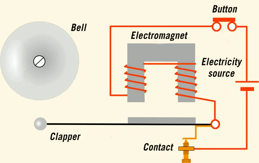
The above stated animation depicts the working of an electronic door bell. Once the switch is turned on, the circuit is active which further makes the solenoid to activate the plunger. The plunger then hits the bell.
Simulink model :
The simulink model for the working of the eloctronic doorbell was attached below.
It involves the following condition that the switch is closed for 2 seconds and then released.
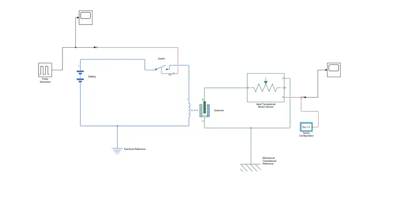
First of all the blocks represented in blue refers to the Electrical segment and the ones in green belongs to the Mechanical segment.
A pulse generator block was used to feed the input. The inputs were mentioned below
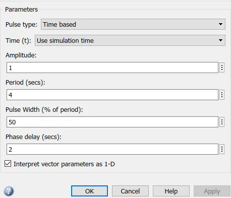
Here the amplitude was left undisturbed with the default value of 1.
The period was given a value of 4 s , the pulse width was set to 50% of the period and it had a phase delay of 2 s.
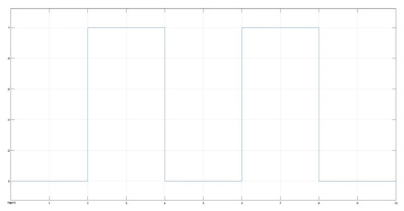
From 0-2 s the amplitude remains 0 and at the end of 2 s the amplitude raises to 1 and stays there for another 2 s and it finally comes down to 0 at the end of 4 s. This constitutes a period. The graphgical representation was attached below.
This plot was achieved by connecting a scope block to the pulse generator.
The pulse generator was further connected to a switch using a simulink-ps converter.
The switch was connected to a battery and a solenoid block. The solenoid block links the electrical and the mechanical segements.
In order to sense the motion a the plunger , an Ideal Translational Motion Sensor was used.
This sensor was further connected to a scope block inoder to obtain the displacement plot of the plunger using a ps-simulink converter.
A solver configuration block was attached and the circuit was grounded using Electrical Reference and Mechanical Reference respectively.
Output :
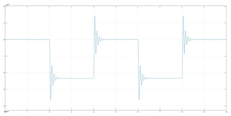
The simulation had a runtime of 10 s. The Vibration in the plot indicates the movement of the plunger to strike the bell at an interval of 2 s with a phase delay of 2 s.
STUDY 2 : Simulation of a Temperature sensing Fan
Thermistor :
A thermistor is a resistance thermometer, or a resistor whose resistance is dependent on temperature. The term is a combination of “thermal” and “resistor”. It is made of metallic oxides, pressed into a bead, disk, or cylindrical shape and then encapsulated with an impermeable material such as epoxy or glass.
They're perfectly suited to scenarios where one specific temperature needs to be maintained, they're sensitive to small changes in temperature. They can measure liquid, gas, or solids, depending on the type of thermistor.
Circuit :
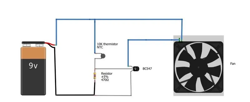
The above mentioned image shows the setup of a temperature sensing fan.
Simulink model :
The simulink model for the working of a temperature sensing fan was attached below.
It involves the following conditions
- Temperature source: 20 °C from 0 to 10 seconds, 27 °C from 10 to 30 seconds, 23 °C from 30 to 50 seconds.
- Switch ON the fan when the temperature is above 25 °C.
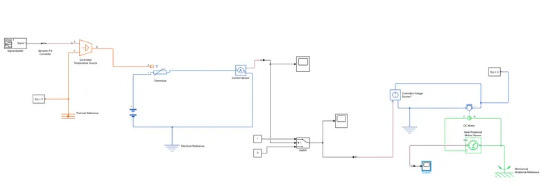
First of all the blocks represented in blue refers to the Electrical segment, the ones in green belongs to the Mechanical segment and the red ones refers to the Thermal segment.
Initially the temperature inputs are defined using a signal builder. The inputs are given and depicted below.
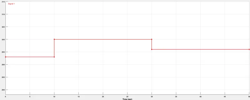
The Temperatrue was fed in terms of kelvin.
As per the given conditions for 0-10 s the temperature remains at 293 K , for 10-30 s it changes to 300 K and for 30-50 s it becomes 296 K.
The inputs are further fed into a controlled voltage source as filtered inputs with calculated derivatives of first order through a simulink-ps converter.
The output from this voltage source was connected to a thermistor which was connected in series with a current sensor and a battery block.
The current sensor was connected to a scope which provides the nature of the current flowing by means of a plot. The plot was attached below.
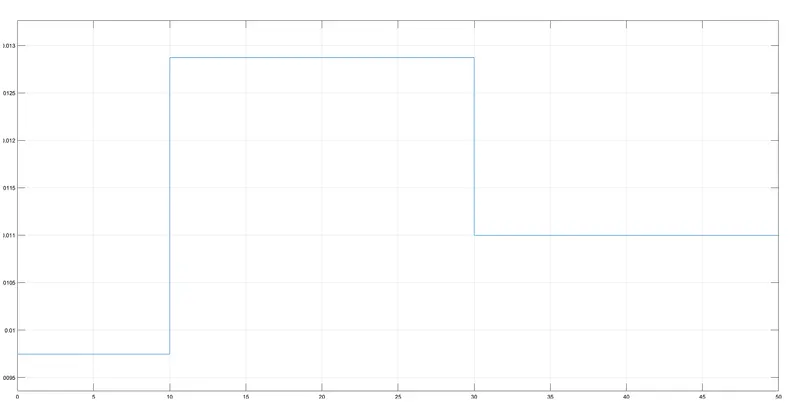
From the plot we can observe that for a value above 0.011 , the temperature lies above 296 K (23 °C ) which eventually closes on 298 k (25 °C) which was the condition for the fan to run.
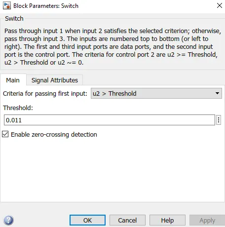
The current sensor was further connected with a switch block where the threshold value was fed. The switch block has 3 inputs out of which, input 1 & 3 are assigned based on the threshold criteria.
The input 1 was attached to a constant 1 and the input 3 was attached to a constant 0 , the desired output was obtained based on the criteria.
The input 2 was connected to a scope block inorder to visualize the results based on the temperature.
Therfore the switch turned ON when the criteria was satisfied and it turned OFF when the criteria failed.
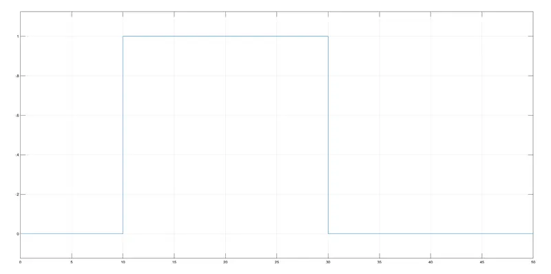
From the above plot it was clear that the switch returns a value 1 when the temperatrue criteria satisfies and returns 0 when criteria fails.
The switch was further connected to a controlled voltage source.
This voltage source was then connected to a DC motor which bridges the electrical and mechanical segments.
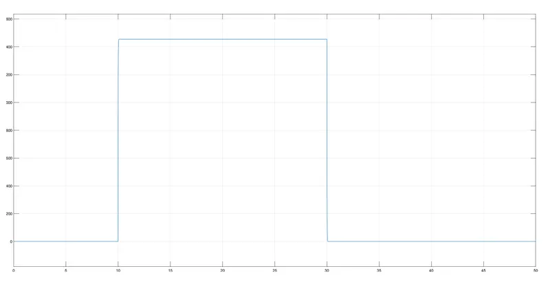
Inorder to observe the motion of the DC motor, it was attached to an Ideal Rotational Motion Sensor. This sensor provides the angular velocity and angular displacement of the motor. A scope is attached to its W port inorder to observe the behaviour of the velocity.
Necessary solver configuration blocks were attached and the circuit was ground using Electrical, Mechanical and Thermal References.
Output :
The Simulation had a runtime of 50 s. The underlying plot represents the fan speed and it clearly runs only when the temperature conditions were satisfied.
The fan runs only during 10-30 s as the temperature was 27 °C which satisfies the given condition.
CONCLUSION :
The given objectives were successfully achieved using simulink which includes,
- A door bell using a solenoid.
- A temperature sensing fan using a thermistor.
It was made sure that all the given conditions were satisfied during simulation.