DESIGN OF PLASTIC COVER OF A BIKE
ABSTRACT
As a part of my Internship with Skill-Lync, I was offered to do a project of creating a CAD model of Plastic cover of a bike which is an Automotive Plastic Product. A Class A surface of the Plastic cover was provided which was further used to develop the model. This model in accordance with the concepts acquired from the Skill Lync’s course work “Automotive Plastic Design using CATIA v5”.
These Plastic covers are generally used in covering the components such as battery and the other interior units. They also provide an aesthetic look to the automobile which makes the automobile appealing to the consumers.
The given Class-A surface was used to develop the Class-B and Class-C. These created surfaces were trimmed and joined together in order to form a closed surface using which a solid component was created eventually. An additional flange was created in order to house the screw boss which was also provided as an input in the Class A surface.
Further the Draft analysis was performed to ensure the smooth manufacturing of the product. The required tooling axis for the component was also created.
1. STAGES OF PRODUCT LIFE CYCLE IN AUTOMOTIVE INDUSTRY
The Product Lifecycle also defines on how fast the OEM will need to work either to upgrade the model or bring the next model in the pipeline. Agility of the carmaker will make all the difference here. OEMs who can assess the market condition well in advance and are able to upgrade or launch a new model will have higher chances to gain market share.
- The various stages of product life cycle in Automotive Industry are,
- Concept Sketching
- Styling Class-A
- Feasibility Check
- Concept Validation
- New Product Design
- Development Stage
- Prototype Build
- Design Validation
- Pilot Production
- Mass Production
1.1 Concept Sketching
The purpose of concept sketching in engineering domain is to provide communication at early stages of the design which is a collection of visual cues sufficient to suggest the design to an informed observer.
Free hand sketching is typically used with often a considerable number of iterations which generates visual thinking through series of sketches.
1.2 Styling Class-A
In this phase the initial concept sketch is validated for design aestheticism and CLASS A Skin is developed through software such as Alias. In this phase the initial 2D SKETCHES from Concept design get transformed in to 3D using Design Software such as Autodesk Alias.
A Clay model will be developed based on the inputs and Finally the model is scanned and fed to the CAD Engineers to develop the for the next stage.
1.3 Feasibility Check
This phase kick starts the design engineering process and the received Class A surface is validated for further stages of production feasibility.
In this phase, Feasibility study involves carry over designs for some parts from previous models and can be used in the new models.
In this way lead time is improved and also the functional and aesthetic traits are carefully validated
This is the stage that does the market study of various components and also incorporates the feedback from the customers and stakeholders and updates that to the downstream processes.
Instance: If there is a feedback from the customer about lack of space to keep wallet and phone in the centre console for a car then that will be validated and new concept is developed to create bin in the console and it will be passed on to the downstream processes to ensure it is attainable.
1.4 Concept Validation
In this phase Initial Concept Validation of perceived model is done. This is where all the design rules were validated and various studies such as Visibility Check, Safety Check from driver’s perspective were studied and all parts are started building around it
For instance, an interior trims firm does a Meter Visibility study to check the driver's vision range and carefully devise the mandatory information and tachometer reading within the visible range of the rider. All the research carried out were used to prepare a master section that will be used to develop different parts involved in the Interior Design such as IP, Infotainment systems, Steering Column.
Master Section is formed at the end of initial concept validation which will processed for further downstream.
1.5 New Product Design
The major work of product designer starts from this phase. After the Concept validation stage, the designer starts developing CAD sketches of every component in the car.
The main objective of the product designer is to incorporate all the inputs from the previous stages and ensure it is 100% manufacturable in the upcoming stages.
Then the role of designer is to do all the design work within the specified rules and design engineering standards of the organization
1.6 Development
This stage forms as the bridge between the Design team and Manufacturing Team. The role of Development team is to collaborate with manufacturers to ensure the design is feasible to manufacture and feasible to assemble
They work with the tool makers, Mould and fixtures and also with various outsourced vendors and stakeholders to kick start the manufacturing of the designed part
1.7 Prototype Build
The next stage is to do proto-build of the designed part. A complete prototype is built to study the feasibility of the manufacturing process and materials used in the components
1.8 Design Validation
The Design validation stage inspect about any failures in the prototype like Plastic deformation or Dimensional instability and thy rectify the process and materials. This is the phase where further design modifications are freezing and only minor changes are allowed.
1.9 Pilot Production
The main role of the pilot production is to devise the lead time and manufacturing processes of various components and any defects in the Production line will be identified and an assembly line is devised with different stations.
1.10 Mass Production
After ensuring all the above stages the Production of the components will be made live to Mass Production. These are the stages of an Automotive Life Cycle.
2. CLASS A SURFACE
2.1 CLASS A
In automotive design, a class A surface is any of a set of free form surfaces of high efficiency and quality. The minimum math requirement for Class A Surface is that the transition across the edge is a continuous curvature.
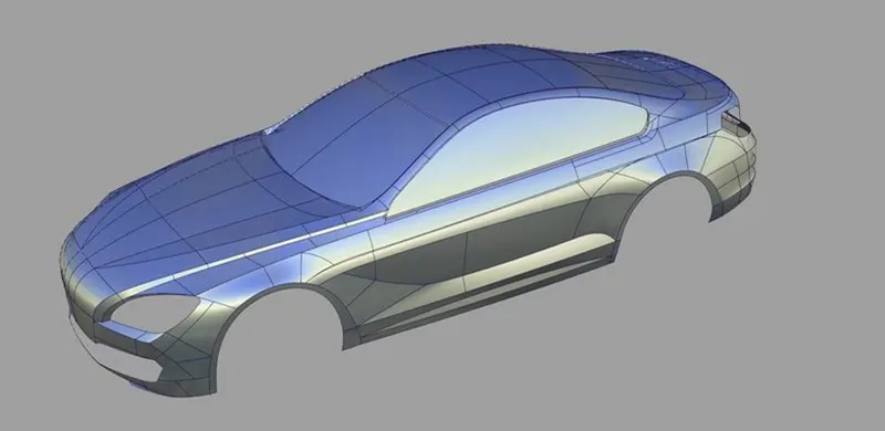
FIG 2.1.2 CLASS-A SURFACE
Another way to describe this is in a situation where a reflection is cast upon the surfaces and you would not be able to tell where one patch ends and the other begins. Class-A Surfacing needs a fine blend of keen visualization skills, artistic insight Engineering, experience and domain knowledge.
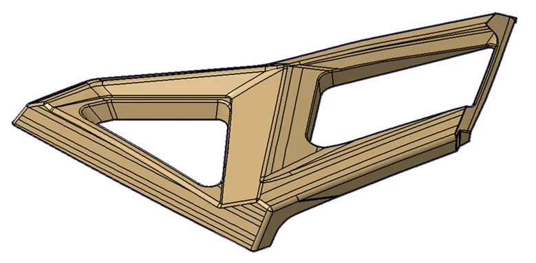
Fig 2.1.2 Class-A surface of Plastic Cover
2.2 Types of Continuity
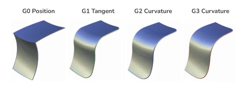
Surface continuity defines how smooth one surface transitions to another. The smoothness of a junction is generally defined using an index ‘G’. If the two surfaces are not touching it can be represented as ‘No-G’
The four types of surface continuities which are differentiated based on the contact which the establish with each other are
- G0 – Position (touching)
- G1 – Tangent (angle)
- G2 – Curvature (radius)
- G3 – Acceleration/Torsion (rate of change of curvature)
Fig 2.2.1 Types of Continuity
3. CLASS B SURFACE
Class-B surface resembles an offset surface from Class-A. The thickness to which extent the actual component is required is basically the offset distance for the Class-B surface.
The Class B surface has minimal imperfections and are not often visible outside. For plastic components the offset is generally around 2-3 mm.
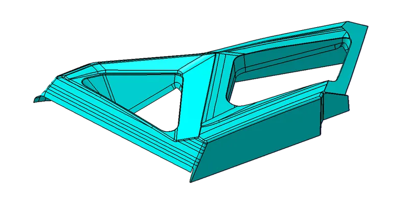
Fig 3.1 Class-B surface of Plastic Cover
4. CLASS C SURFACE
Class-C surface is the surface that binds the Class-A and Class-B surface and forms a closed surface. In the Class-C surface, more imperfections are allowed compared to the Class-A and Class-B surfaces.
These surfaces are also not readily visible and are accessed only during installation or during the service of a particular component.
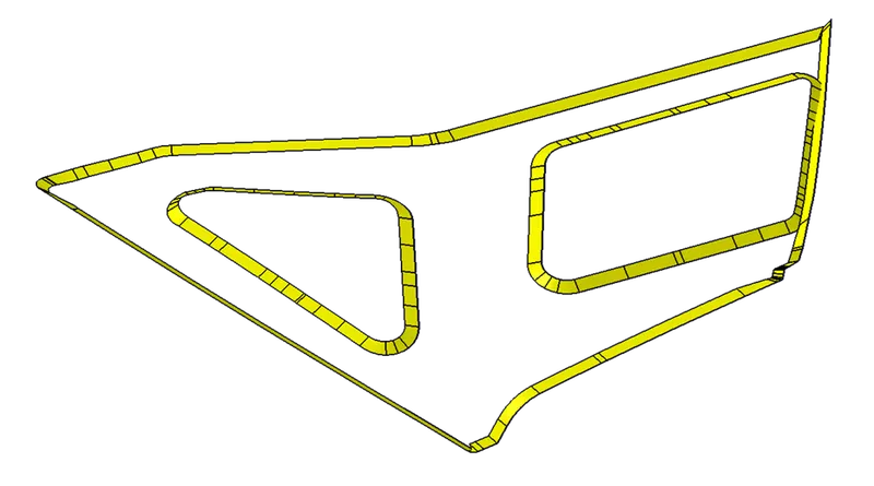
Fig 4.1 Class-C surface of Plastic Cover
5. DRAFT ANALYSIS
5.1 DRAFT
Draft is a method of ensuring that the plastic component is ejected out of the mould cavity without any damage to its surfaces. Basically, a taper is provided to the surface of the component so that it is not exactly parallel to the direction of mould opening.
A single value of draft cannot be applied to all the components. There are various factors that influence the draft angle for a particular component such as wall thickness, shrinkage rate, ejection, material selection. It is also known as Taper allowance.
Generally, a minimum draft of 3 degree is used for plastic components for a shutoff and a draft of 0.5 degree is used for the vertical surfaces.
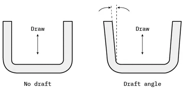
Fig 5.1.1 Draft angle
Providing draft also helps in improving the surface finish of a component. If the draft is not provided, the component might rub against the mould cavity during ejection which results in poor surface finish.
5.2 DRAFT ANALYSIS ON PLASTIC COVER
The component clears the draft angle of 3 degree and the ribs clear a draft of 0.5 degree.
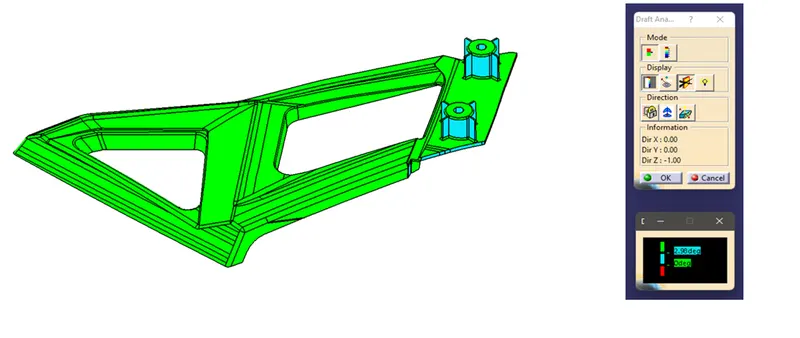
Fig 5.2.1 Draft Analysis on the Plastic Cover
6. FACTORS INVOLVED IN MATERIAL SELECTION
In manufacturing process selection of materials for the design of a machine is an essential step to accomplish the reliable functionality of the machine.
The selected material should satisfy both the availability as well as the function and many other factors such as,
- Mechanical Forces or Loads,
- Wear and tear
- Electrical insulation
- Thermal properties
- Availability & cost
6.1 Mechanical Forces or Loads
There is the different type of mechanical forces can act on machine members and produces different stress and strains. These following actions produce the different types of forces in the machine parts.
- Self-weight of the machine
- Energy Transmitted
- Change of temperature
- Frictional resistance
- The inertia of reciprocating parts
- Unbalance of Moving parts.
6.2 Wear and Tear
As the moving parts or sliding parts needed to withstand the wear and tear as they getting aged. So, this is also a factor that makes the difference in selecting a material for the machine parts.
6.3 Electrical insulation
It is very important that whether the component should resist the electric current between the two mated components, or it is not necessary to insulate the current. So there are some special materials available to resist the electric current. PVC, glass and asbestos are the examples of Insulation material. These insulating materials can be used in between the mating parts to resist the electrical current.
6.4 Thermal properties
Thermal properties of the materials, that are necessary to consider while picking a material for a machine part. it might affect the mechanical properties of the materials due to the heat. In some applications, it is necessary to insulate the thermal energy to flow between the mating parts.
6.5 Availability & Cost
Finally, the most important factor is that the availability of the material resource. From the economical point of view, the material should be easily available in nature. This availability decides the cost of the material. So, it is necessary to consider this factor as the major one in the selection of materials for the engineering purpose.
By considering these factors, we can select a suitable material that can fulfil the designer requirement from all perspectives such as the functionality, Cost, availability to build reliable machines.
7. PLASTICS IN AUTOMOTIVE SECTOR
Plastics are a very appealing material for automobiles because their use leads to greater fuel efficiency. It has been determined that every 10 percent drop in vehicle weight equals a 5 percent to 7 percent decrease in fuel usage. The use of plastics in the Automobiles has grown significantly since the 1950s.
There are two different types of plastics which are commonly used in the manufacturing of Automotive Plastic products which are,
- Thermosetting Plastics
- Thermoplastics
7.1 Thermosetting Plastics
A Thermosetting polymer, resin or plastic often called a thermoset, is a polymer that is irreversibly hardened by curing from a soft solid or viscous liquid prepolymer or resin Curing is induced by heat or suitable radiation and may be promoted by high pressure or mixing with a catalyst. It cannot be recycled.
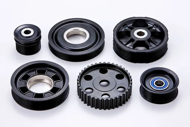
Fig 7.1.1 Examples of Thermosets
In general, thermoset products are made through liquid moulding processes. The polymers and other agents are fed into tanks or barrels, where they are heated to a liquid state and mixed.
Then the liquid polymers and other agents are injected into a mould cavity. As the material cools and hardens to the configuration of the cavity, it goes through a curing process where the polymers cross-link together.
That process forms an irreversible chemical bond that prevents the risk of melting, softening or warping when or if the finished product is subjected to high heat or corrosive environments. This makes thermosets perfect for high-heat applications and outdoor use.
There are two primary liquid moulding processes used to produce thermoset plastics,
- Compression moulding
- Thermoset Injection moulding
- Sheet moulding component
7.2 Thermoplastics
A Thermoplastic or Thermosoftening plastic is a plastic polymer material that becomes pliable or mouldable at a certain elevated temperature and solidifies upon cooling. Most thermoplastics have a high molecular weight. It can be melted and recycled.
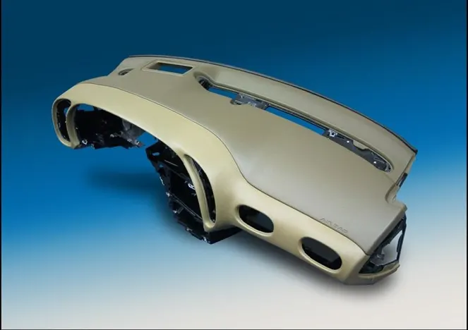
Fig 7.2.1 Example of Thermoplasts
Thermoplastic sheets are manufactured from raw materials, including polymer resins, colorants, and additives, depending on the specific formulation required. Raw materials are blended to exacting standards to ensure uniformity throughout the batch and consistency between batches.
Once the raw materials are blended, they are heated, pressed through an extrusion die, and drawn into a sheet through a set of rollers. While the sheet is still warm, it passes through additional roller sets to reach the desired thickness and specified surface texture.
Thermoplastics are characterized by their pliability above a specific temperature, and ability to re-solidify upon cooling. This allows them to be easily shaped and moulded without changing the properties of the thermoplastic material.
- The manufacturing processes include,
- Injection moulding
- Extrusion
- Blow moulding
- Reaction Injection moulding
8. CONCLUSION
The solid model of the Plastic cover was created using the given Class A. This solid model was made through the further creation of Class-B and Class-C surfaces which were created using CATIA V5.
Following the solid component, the required screw bosses were created including the additional flange to support them.
The Draft analysis for the component was performed and it was made sure that the component cleared the minimum draft in both the tooling directions.