Week 2 Air standard Cycle
AIM :
To study and plot an Otto cycle graph and to find the thermal efficiency.
OBJECTIVES OF THE PROJECT :
To find the Thermal efficiency of the cycle.
To plot a P-V digram of the given cycle.
ABOUT :
Otto cycle is an Air standard cycle which is used in the functioning of spark ignition engines,it was first proposed by Nikolaus Otto over 130 years ago , which operates at constant volume.
Otto’s engine work during the eve of the industrial revolution was a critical development leading to the dawn of the automotive industry in the late 19th century.
Today the Otto Cycle is frequently associated with an ideal cycle analysis of automotive spark ignition gasoline internal combustion.
To a first order this Otto Cycle analysis can provide insights into how engine efficiency is affected by changing operating and design parameters. Engines operating under the Otto Cycle are the principal power-plants used in automobiles worldwide at the present time, although in some regions of the world the Diesel Cycle is a very close second in automotive applications.
Engines operating under the Otto cycle are relatively inexpensive to manufacture and provide reasonable power to weight ratios with good efficiencies. In recent years engine design improvements coupled with exhaust after-treatment have resulted in vehicles that produce very low levels of pollutants.
PROCESSESS INVOLVED :
1-2 Isentropic Compression
2-3 Isochoric Heat Addition
3-4 Isentropic Expansion
4-1 Isochoric Heat Rejection
The cycle begins with the intake stroke in which fresh reactants (fuel and air) are drawn into the engine’s cylinder by a downward-expanding piston motion.
The second stroke is compression in which the piston moves from the bottom to top of the engine thereby reducing the volume of the fuel and air.
Compressing the reactants before burning them allows for greater work and power to be extracted from the following combustion process.
When the piston is near the top of its stroke combustion begins and expansion of the burned gases continues into the expansion stroke.
The last of the four strokes is the exhaust stroke in which the burned products of combustion are pushed out of the engine in order to make space for the next cycle’s intake stroke.
PROCEDURE :
Using the bore,stroke and compression ratio of an engine the paramaters such as Swept volume and clearance volume were calculated. Further , the ideal pressure and temperature values were used along with the known volumes inorder to calculate the corresponding state variables at the remaining points(pressure in pascal, volume in mm and temperature in kelvin).
The following equations were used inorder to find the state variables
Ideal gas equation (P*V)/T= constant
Reversible adiabatic equation PV^gamma = constant (gamma-adiabatic index)
General Expression for Thermal Efficiency = Work done/ Heat supplied
where, work done = heat supplied - heat rejected
Thermal Efficiency of Otto cycle = 1 - (1 / (r ^(gamma-1)))
where , r = compression ratio (Vt/Vc)
In this case the engine kinematics of an Audi A6 had been taken into consideration.
bore = 0.0845 m
stroke = 0.0890 m
connecting rod length = 0.15 m
Therefore these inputs were considered inorder to calculate the required outputs using a Python code.
import math
import numpy as np
import matplotlib.pyplot as plt

# Inputs
p1 = 101325
t1 = 500
gamma = 1.4
t3 = 2300

# Engine geometry
bore = 0.0845
stroke = 0.0890
r = 10 # Compression ratio
rad = stroke/2 #  Crank radius
l = 0.15 # Connecting rod length
n = l/r # Obliquity ratio

def Engine_Kinematics(bore,stroke,l,r,start_crank,end_crank):

# Volume rqquired
	V_s = (math.pi/4) * (bore**2) * stroke
	V_c = V_s/(r-1)

	num = 50
	n = l/rad
	V = []
	sc = math.radians(start_crank)
	ec = math.radians(end_crank)
	dtheta = (ec - sc) / (num-1)

	for i in range(0,num):
		theta = sc + i*dtheta
		term1 = 0.5*(r-1)
		term2 = n + 1 -math.cos(theta)
		term3 = (n**2) - (math.sin(theta)**2)

		Vol =(1 + term1*(term2 - (term3**0.5)))*V_c
		V.append(Vol)
	return V

# Volume computation
v_s = (math.pi/4) * (bore**2) * stroke
v_c = v_s/(r-1)
v1 = v_s + v_c

# Isentropic Compression
V_compression = Engine_Kinematics(bore,stroke,l,r,180,0)
P_compression = []
for v in V_compression:
	P = p1*((v1/v)**gamma)
	P_compression.append(P)

# State point 2
v2 = v_c
p2 = p1*((v1/v2)**gamma)
t2 = t1*((p2/p1)**((gamma-1)/gamma))

# State point 3
v3 = v2
p3 = p2*(t3/t2)

# Isentropic Expansion
V_expansion = Engine_Kinematics(bore,stroke,l,r,0,180)
P_expansion = []
for v in V_expansion:
	P = p3*((v3/v)**gamma)
	P_expansion.append(P)

# State point 4
v4 = v1
t4 = t3 / ((v4/v3)**(gamma-1))
p4 = p1*(t4/t1)

# Efficiency
Eff = 1 - 1/(r**(gamma-1))
Efficiency = Eff*100
print('Efficiency of the given Otto cycle is',Efficiency,'%')

# Plotting
plt.plot(V_compression,P_compression)
plt.plot([v2,v3],[p2,p3])
plt.plot(V_expansion,P_expansion)
plt.plot([v4,v1],[p4,p1])
plt.title('OTTO CYCLE SIMULATOR - P-V DIAGRAM',fontsize = '15')
plt.xlabel('VOLUME',fontsize = '15')
plt.ylabel('PRESSURE',fontsize = '15')
plt.text(0.0004,3000000,'Efficiency 56.47 %',fontsize ='15')
plt.show()
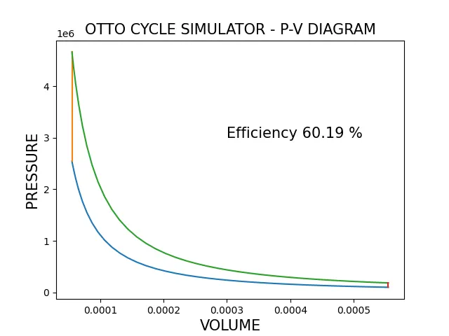
The function Engine_Kinematcis was used to determine the volume during compression and expansion processess.

OBSERVATIONS :
The above graph clearly indicates the nature of various processess.
The curved lines indicate the Isentropic processess.
The straight lines indicate the Isochoric processess.
OUTPUT :
The Thermal Efficiency of the Otto cycle was found as 60.19 %
The combustion efficiency is directly proportional to the air-fuel ratio.Higher values for the combustionefficiency can be obtained by reducing the compression ratios and providing leaner mixtures.
CONCLUSION :
Otto cycle is a basic Air standard cycle used in the SI engines. The given Python program can be used to find the efficiency and to plot the cycle. Various other engine kinematics can be incorporated in this code to find and visualize the corresponding data. Functions provide more flexibility, primarily because input values were passed and output values were returned. Thus desired engines can be analysed and studied using this code.