Door Applique Design with Engineering Features
AIM :
To create the Door Applique Plastic component through the given Class-A surface.
OBJECTIVE :
- To create the solid models of Door applique AND Door attachment feature.
- To create Tooling axis for the component.
- To create Locators and Heat Stakes for Door applique.
- To perform the Draft Analysis for the component.
HEAT STAKES :
- Heat Staking is a pulsed-heat process to join two or more parts out of which one at least is made of plastic.
- This process is use to lock another plastic or metal component of an assembly in place.
- The insert is preheated with induction and then pressed into a hole in the plastic part.
- They simplify and reduce the cost of the machinery.
- A Draft of 0.5 degrees per side is the maximum limit.
- These Heat stakes must be lesser in length than the locators.
LOCATORS :
- Locators are components present in plastic design which are used to hold the components in place.
- These are used to arrest the degrees of freedom of a component.
- The types of Locators include 4-Way locator and 2-Way locator.
- A Draft of 0.5 degrees per side is the maximum limit.
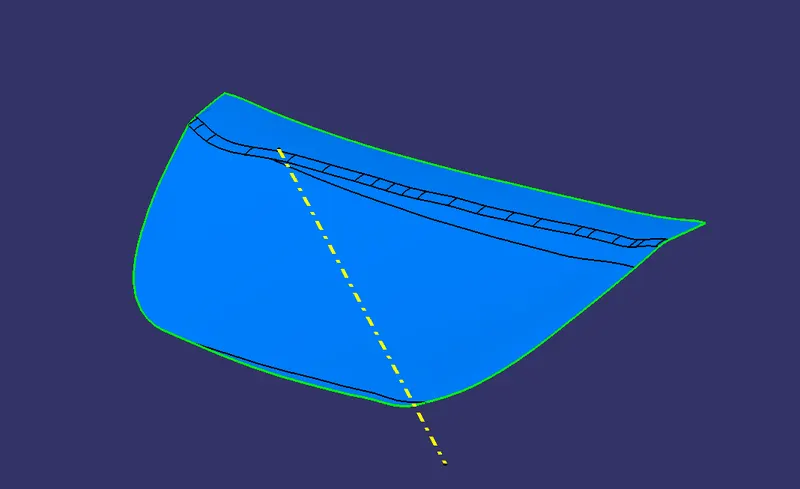
CLASS A SURFACE:
- Class A surfaces are those surfaces which are curvature continuous while providing the simplest mathematical representation needed for the desired shape and does not have any undesirable waviness.
- The Class A surface is the used to begin the design of a product.
- All the further intricacies of the component are created based on the Class A surface.
CLASS B SURFACE :
- The Class B surface is created from the Class A surface , keeping the thickness of the component in check.
- The Class B surface resembles an offsetted surface from the Class A.

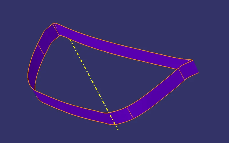
CLASSS C SURFACE :
- The Class C surface is used to bind the Class A and Class B surface together inorder to form a closed surface.
PROCEDURE :
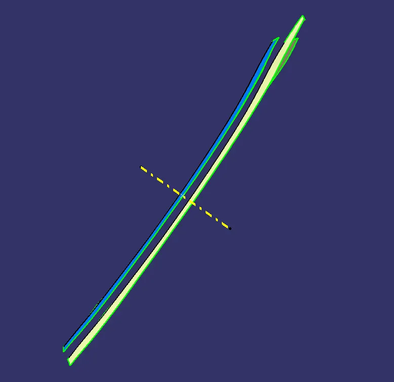
Creating Tooling Axis
- A point was created on the Class A surface using the location as 0 mm.
- A line was created passing through this point along Y axis to serve as the main tooling axis.
DOOR APPLIQUE
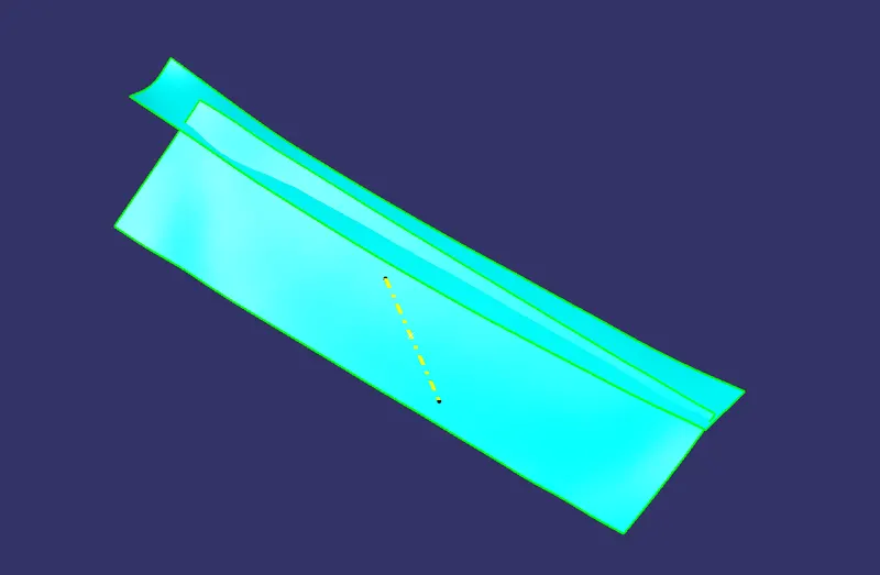
Creating Class B Surface
- The required surfaces were obtained from the Class A surface using Extract command.
- These surfaces were further expanded using Untrim and Extrapolate commands.
- These surfaces were offsetted to a distance of 2.5 mm from the Class A surface.
- The protuding surfaces were trimmed using the Trim command and a proper continuous surface was obtained.
- The necessary fillets were added to the Class B surface.
Creating Class C Surface
- The Class C surface connects the Class A and Class B surface.
- Initially the outline of the Class A surface was obtained using the Boundary command.
- The Curve smooth feature were used to enhance the the obtained surfaces.
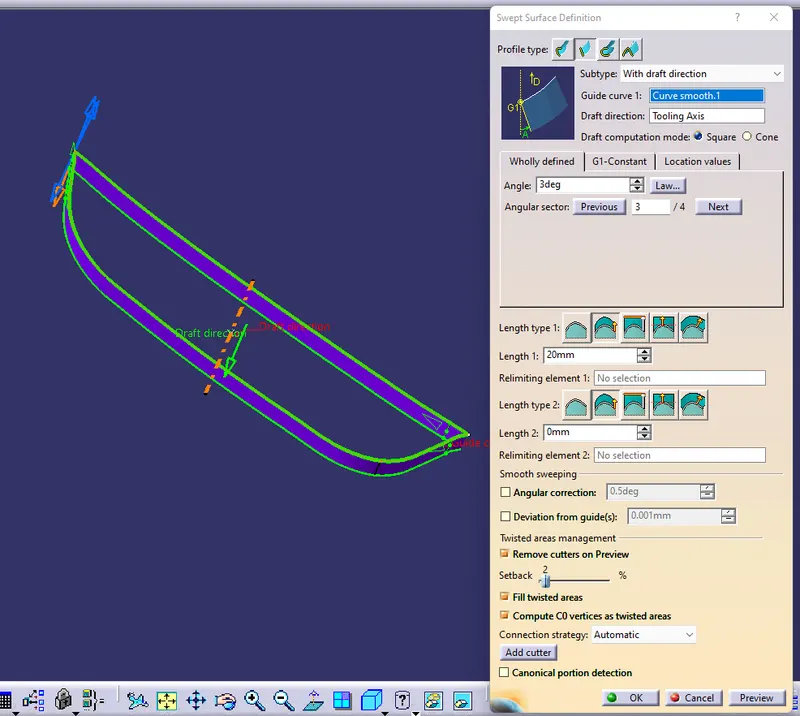
- The the Sweep command was used along With draft direction, with a draft angle of 3 degree.
- The Curve smooth feature were used to enhance the the obtained surfaces.
- The required portions were Extrapolated and Trimmed.
Creating Solid Body
- Finally the Class A, B and C surfaces along with the hole were trimmed together to form a closed surface.
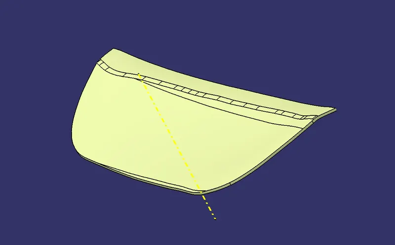
- Using the surface created the solid component was obtained using the Close surface feature present in the part workbench.
DOOR ATTACHMENT FEATURE
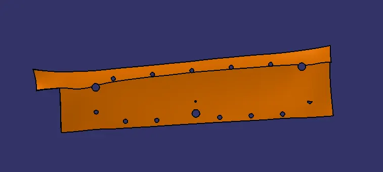
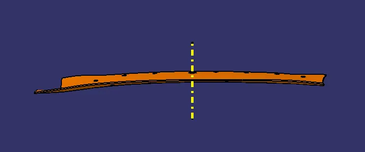
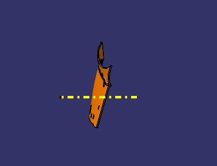
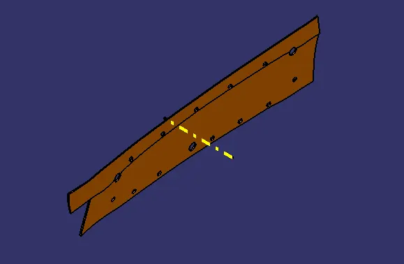
- The Door attachment feature was created using the Thick surface feature for a thickness of 2.5 mm.
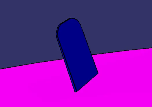
Creating Locators
- A sketch was created on a plane which was created on the point at the middle.
- The sketch was loacted at one end of the Door Applique.
- The sketch consisted of two lines of 15 mm each intersecting at the middle.
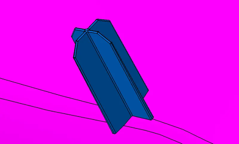
- This results in the creation of a 4-way locator.
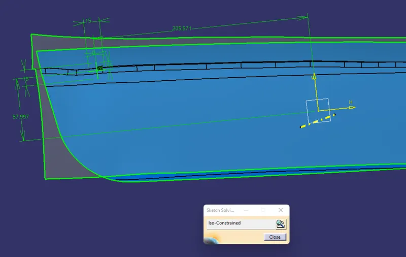
- This was extruded using the Thicken option in the Pad command , with a thickness of 1.3 mm at neutral fiber which is 40 % of the main wall thickness.
- A Draft of 0.5 degree was provided.
- The required fillets and chamfers were also provided.
- This 4-way locator was copied and translated to the other end of the aplique.
- A sketch was created on a plane which was created on the point at the middle.
- This time the sketch was at the middle of the component.
- The sketch consisted of a single line of 15 mm in length.
- This results in the creation of 2-way locator.
- All the locators were attached to the main body using Boolean operations.
Creating Heat Stakes
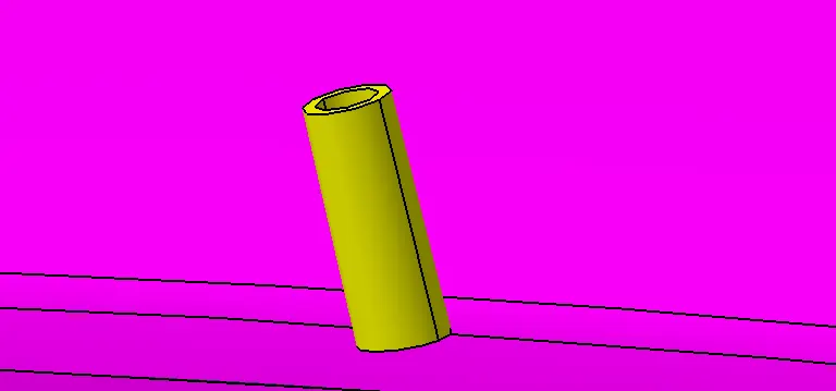
- A sketch was created using the same plan as earlier.
- This sketch consist of two circles with an inside diameter of 5 mm and an outside diameter of 7 mm.
- It was extruded to a length less than the locators.
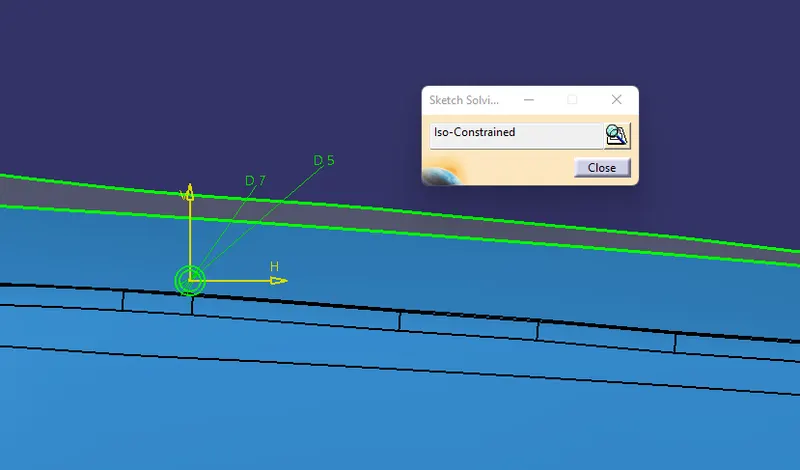
- This extruded part was further used to create multiple heat strakes.
- The outer boundary of the Class A surface was extracted.
- This bounder was offsetted using the parallel curve feature.
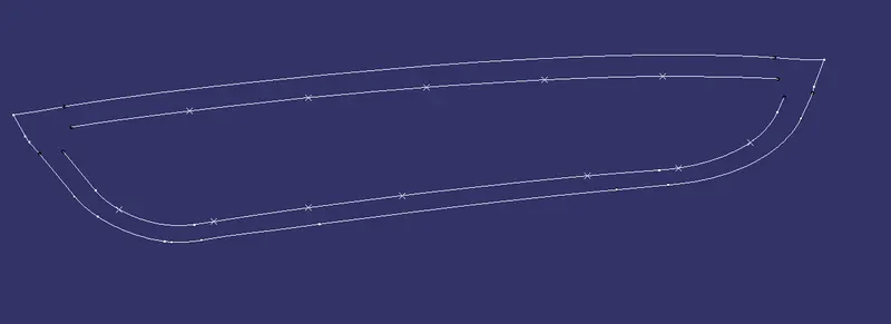
- Multiple points were created on this inner curve.
- These points were used to create multiple heat stakes using the one which was created earlier using the Translate feature.
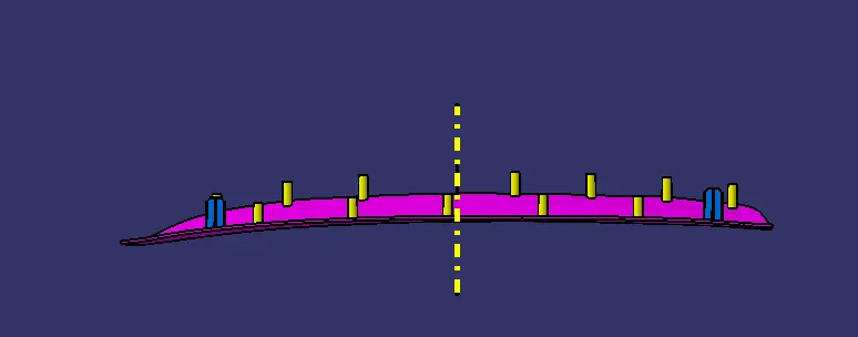
- Thus 5 heat stakes on top and 7 heat stakes at the bottom were created.
- A Draft of 0.5 degree was provided.
- All the heat stakes were attached to the main body using Boolean operations.
Creation of Counterpart Clearances
- Required holes were created on the Door attachment feature surrounding the locators and stakes.
- The clearance gap for the Locator wall must be 0.1 mm.
- The clearance gap for the Heat stakes must be 0.5 mm.
- Sketches were created accordingly and holes were created using the Boolean operations.
Draft Analysis
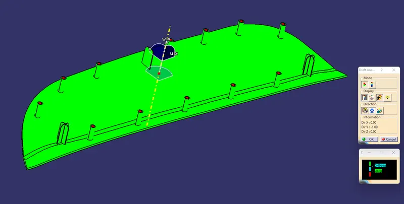
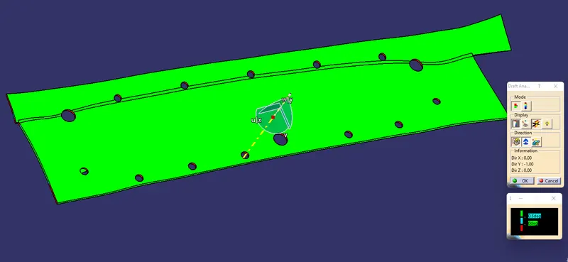
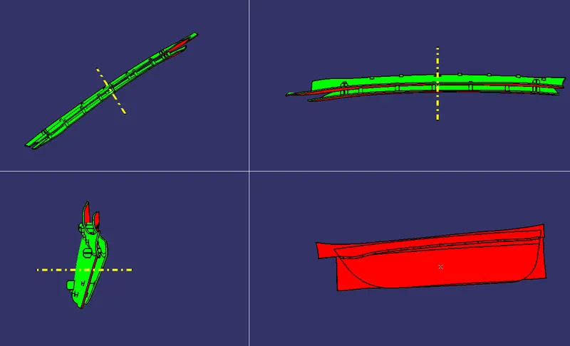
- The Drafting analysis was performed using the Feature Draft Analysis command.
- The Draft analysis was performed for both the components for a draft angle of 0.49 degree and 0.5 respectively.
MODEL RESULTS :
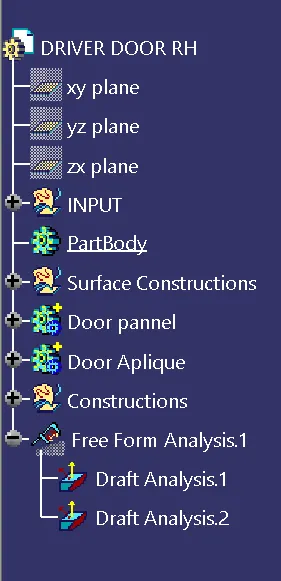
Feature tree
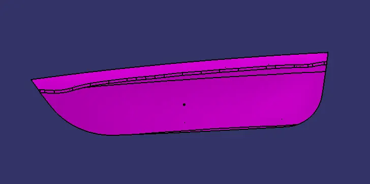
DOOR APPLIQUE
Front view
Top view
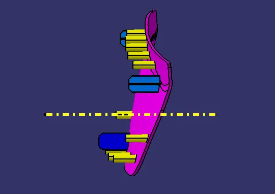
Side view
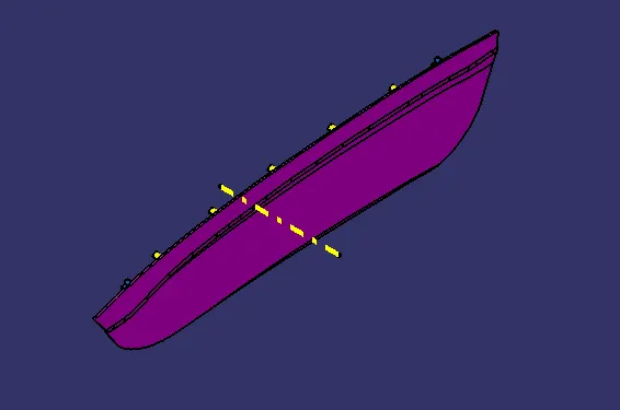
Isometric view
DOOR ATTACHMENT FEATURE
Front view
Top view
Side view
Isometric view
CONCLUSION :
- The Tooling Axis for the component was created.
- The Door Applique and Door attachment feature was created from the surface geometry.
- Locators and Heat stakes were created at appropriate positions.
- Necessary clearances were provided to the locators and heat stakes.
- The Draft Analysis was performed for both the components.
- Necessary images and files were attached.