3D Finishing 2
AIM :
To study about the various design aspects regarding BIW fixtures.
OBJECTIVE :
- To perform 3D finish and create Rough locators for the Assembly design created earlier.
3D finishing process
- Hole concentricity & hole sizes.
- Machining area.
- Nominality.
- Holes colouring standard.
- Pneumatic lay-outing.
- Gaps checking.
- Fasteners implementation.
- Mylars Splitting as per panel profile.
- Proper renaming of parts/assemblies as per the standard.
Hole concentricity & hole sizes
- Hole concentricity and size of the component must be checked in order to make the assembly process easier.
Machining area
- The Machining area must be highlighted using a proper colour code.
Nominality
- Nominal dimensions must be used in the components in order to ensure proper fit in the assembly.
Holes colouring standard
- Standard colour code must be followed according to the customer requirements.
- Simple hole - Blue
- Threaded hole - Yellow
- Machined area - Cream
- Dowel hole - Blue
Pneumatic lay-outing
- It is the collective presence of various pneumatic pipes which work as an inlet to the pneumatic cylinder.
Gaps checking
- Proper gaps between components must be ensured in order to avoid any damage to the adjacent components.
Fasteners implementation
- Fastners must be implemented in the assembly as per the requirements.
Mylars Splitting as per panel profile
- Mylar splitting must be done with the given car panel.
- It must be ensured before the end of the design process.
Proper renaming of parts/assemblies as per the standard
- Proper renaming of part mus be done as per the standard for easy identification and to avoid confusion.
Once the 3D finishing is done, the entire assembly is further sent for simulation and 2D detailing.
3-2-1 principle
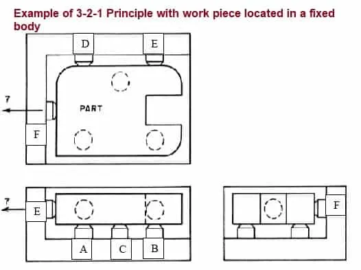
- The 3-2-1 method is a work-holding principle where three pins are located on the 1st principle plane, i.e., either XY, YZ, ZX. And two pins are located on the 2nd plane perpendicular to the 1st plane, and at last, one pin on the plane is mutually perpendicular to the 1st and 2nd planes.
- It represents the minimum requirement for the locating elements.
- The locators along with the clams which hold the part in place, provides equilibrium for all the forces.
- Stability is satisfactory if all three rest buttons are widely spaced and resultand cutting force lies within the triangular area between the buttons.
- If resultant cutting force lies outside the triangular area then it generates a moment which in turn lifts are overturns the component.
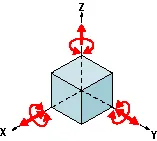
Locating Process in 3-2-1 method
We have two objectives when mounting a part in a fixture for machining
1. Accurately position the part at the desired coordinates.
2. Restrict all six degrees of freedom so that the part cannot move.
A widely used method of accomplishing these two objectives uses the 3-2-1 principle, so-called because it entails three steps that employ three, then two, then one fixed points of known location. Since that adds up to six fixed points, it’s also known as the six point method.
In the three steps of the 3-2-1 method, three mutually perpendicular planes, called datum planes, are introduced, one at each step. These three planes define the workpiece position, and together with opposing clamping forces fully constrain the part. Let’s take a look at the details of the 3-2-1 method
First Plane
Geometry tells us that three points are required to define a plane. This is the "3" in 3-2-1. So, three specific points are used to define the first plane. Fewer than three points cannot define a plane, and in the real world dimensional tolerances mean that four or more points will not be coplanar.
A real-world, less than ideally perfect part placed on four or more reference points will, in fact, rest on only three of the points due to its less than perfect surface. Different parts may rest on different combinations of three points, resulting in variation between finished parts. A stool can be used to illustrate this concept.
A two-legged stool would certainly be unstable. A three-legged stool sits rock-solid. A four-legged stool is often found to rock. In the illustration, a three dimensional part, represented by a cube, is placed on a datum plane defined by three support points.
The part’s six degrees of freedom have now been reduced to three. It can still move along the X or Y axes, and it can still be rotated about the Z axis. The part cannot move along the Z axis because it is held against the plane by clamping force.
Second Plane
A second plane, if it is perpendicular to the first, can be defined by two points, the "2" in 3-2-1.
The part is now constrained to one degree of freedom ,movement along the Y axis.
The part cannot move along the X or Z axes because it is held against the planes by clamping force.
Third Plane
A third plane, if it is perpendicular to both of the first two planes, can be defined by one point, the "1" in 3-2-1. The part is now entirely constrained. It cannot move along or rotate about the X, Y, or Z axes. (Remember that the part is held against each of the three planes by clamping force.
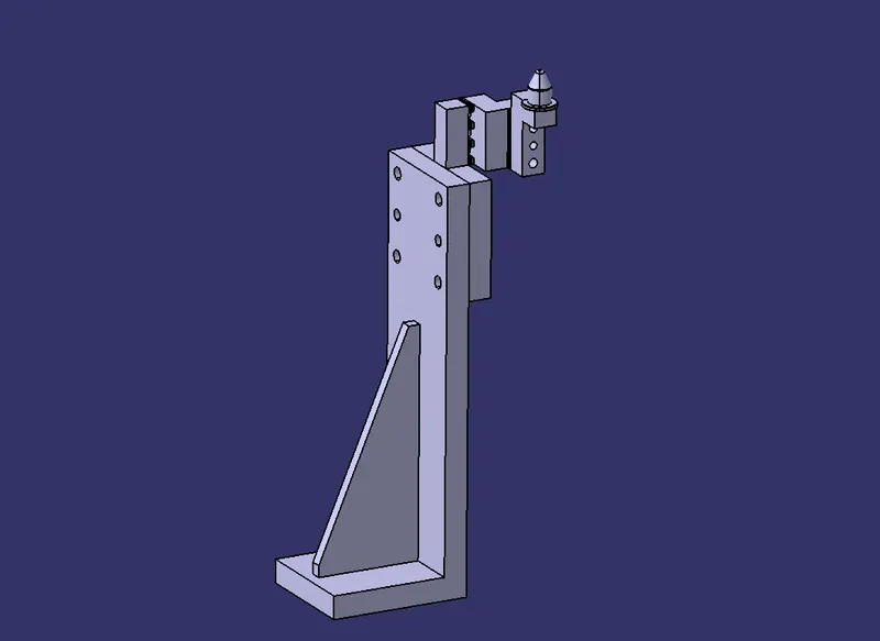
Fixed Pin Unit
The Fixed pin unit is designed to locate the car pannel using different types of pins.
The various parts of a fixed pin unit are as follows,
- Pin
- Pin Reatainer
- Shims
- Block
- Blade / Adaptor plate
- Riser
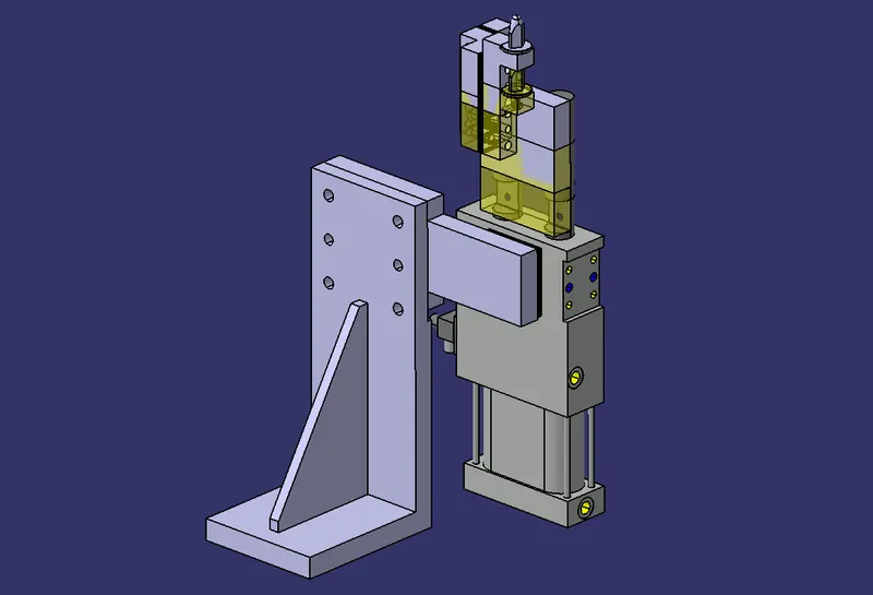
Retractable Pin Unit
The Retractable pin unit is designed to locate the car pannel using different types of pins.
It differs from fixed pin unit with the use of pneumatic cylinders.
The Pin unit will be mounted on the Cylinder.
It contains the same components as that of the Fixed pin unit except the cylinder.
Pneumatic cylinder
Pneumatic cylinders help in the opening and closing of the pin unit, which helps in the mounting process.
The two types of pneumatic cylinders used here were,
- Single rod retractable cylinder
- Double rod retractable cylinder
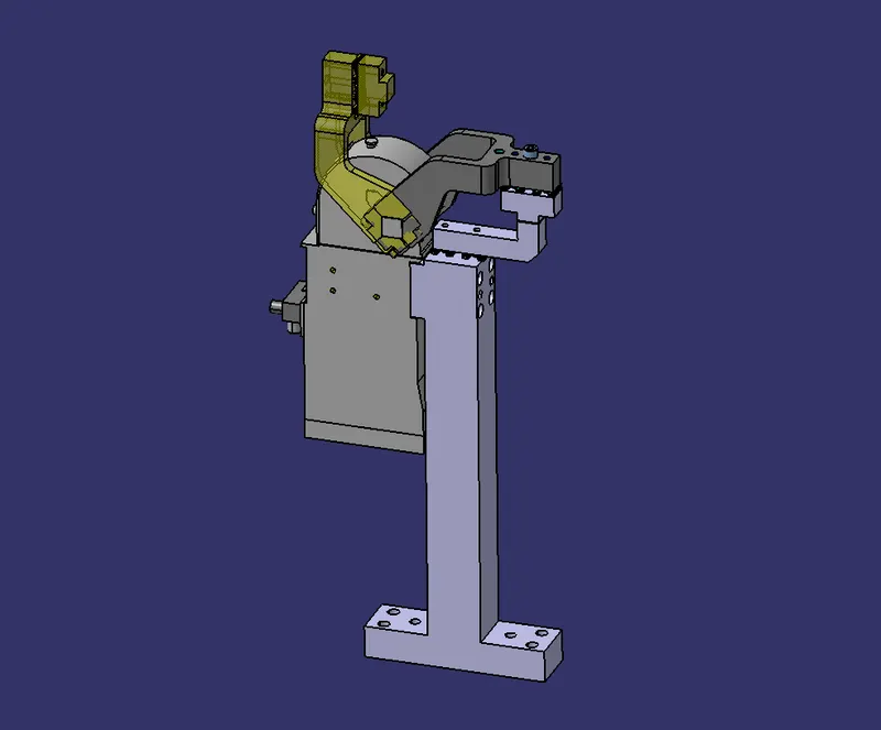
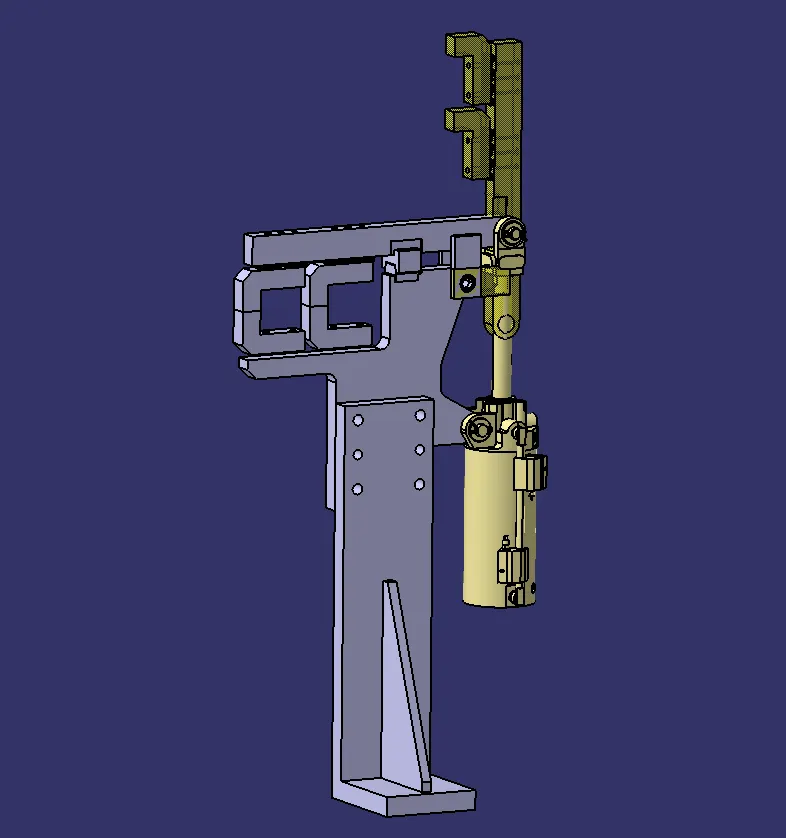
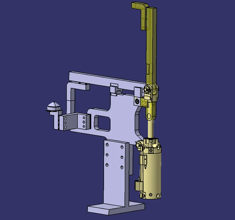
Clamp Unit
A Clamp unit is a unit which is designed to clam or hold the car panel.
The various parts of a Clamp unit are as follows,
- Clamp Arm
- Clamp Cylinder
- Finger
- Rest
- Shims
- Plate
- L Block
- Riser
Rest Unit
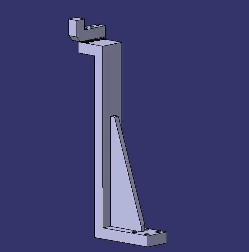
A Rest Unit is used to support the entire car pannel from underneath.
It is a simple unit which used only used to support the panel.
In order to save the overrall cost, it can be combined with other unit such as locating unit.
The various parts of a fixed pin unit are as follows,
- NC blocks
- Shims
- Blade
- Riser
Base Unit
Base Unit is one of the most significant unit of the fixture design because the entire fixture assebmly is mounted over it.
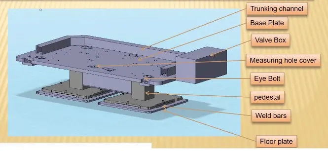
The various parts of a Base Unit are,
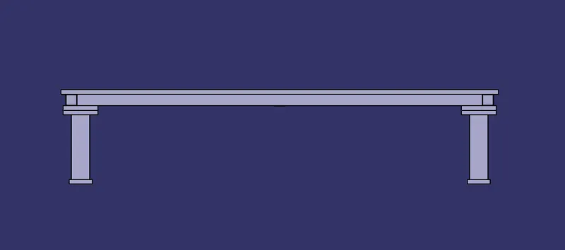
- Base Plate
- Pedestal
- Trucking channel
- Valve box
- Eye bolt
- Floor plate
- Weld bar
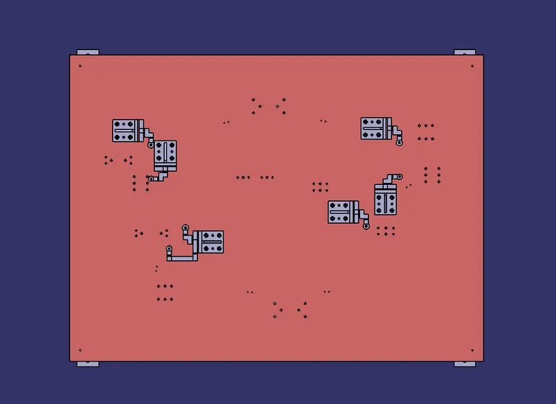
Base Plate
- Base plate is a machined plate of 25 to 40 mm thickness.
- It is generally made up of steel and aluminium.
- The various units such as clamp unit, pin unit etc., are mounted on the base plate using drilled holes.
- A base plate should cover all the units with its outer periphery including opening.
- Datum holes must be covered using cover plates.
Pedestal
-
A pedestal is a part which connects the base plate to the floor plate.
-
In general a pedestal is a standard part and in some cases it can be a welded frame integrated with the base plate.
-
A standard pedestal can be of different height and different sizes.
-
Depends on the size of the base plate, the number of pedestal varies for load distribution.
-
A pedestal are of different types with different inclinations.
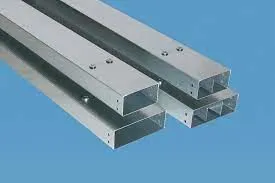
Trunking channel
-
A trunking channel is a duct which accommodates all the pneumatic and electrical hoses and wires for the units of the tool.
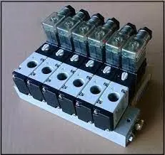
Valve box
- Valve box is a standard part which will accommodates the pneumatic valves for the units.
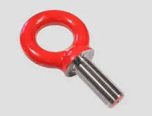
Eye bolt
-
Eye bolts are used for the transporting of the tool from one plate to another.
-
This can be done using lift hooks, fork lift holes will also be provided in some cases for transporting purpose.
Floor plate
- Floor plate is grouned to the floor with fixed bolt on the ground.
- These plates are also called as foundation plates.
-
There will be a clearance of 10mm maintained between the pedestal base plate and the floor plate.
-
This clearance will be used by the levelling screws, for levelling the entire tool.
Weld bar
- Weld bars are be used to weld the positions permanently , after levelling is done.
- A weld bar is a plate along the sides of the base plate of the pedestal.
Rough locators
Rough locators are used to help locate workpieces in the automation process.
Locating refers to the desired location where you want the workpiece to be when it is getting worked on either by a person, team, or robot.
It is a device to establish and maintain position of a part in a jig or fixture.
It can also be called as fool proofing method as the rough locators are set according to the angle of their respective panels.
Thus the parts can be loaded in a defined direction and orientation.
The accuracy of the part locations are very crucial as they affect the final assembly.
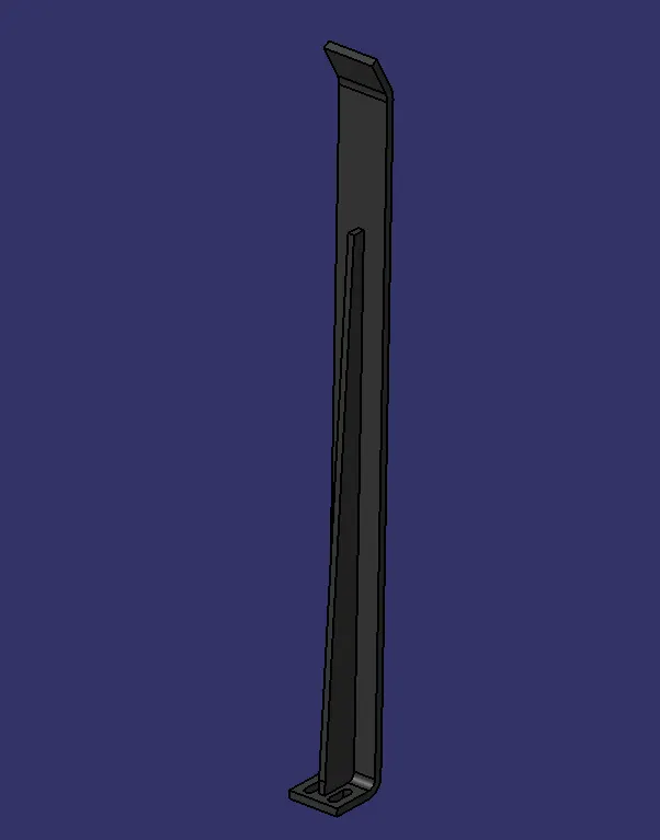
Designing a Rough locator
The points need to be considered while designing a Rough locator are,
- It is used to guide the conponent to place it properly.
- It is generally placed at the edges.
- It must have an entry angle of 30 to 45 degree.
- It must guide the component at a distance of 10 to 15 mm before the engagement
- It is mounted on the base with slots for easy positioning.
- It must be placed at the same angle as the car panel.
- The slots must be in the direction of guiding the car part.
- These locators must be placed within two slots for making the mounting process simpler.
MODEL RESULTS :
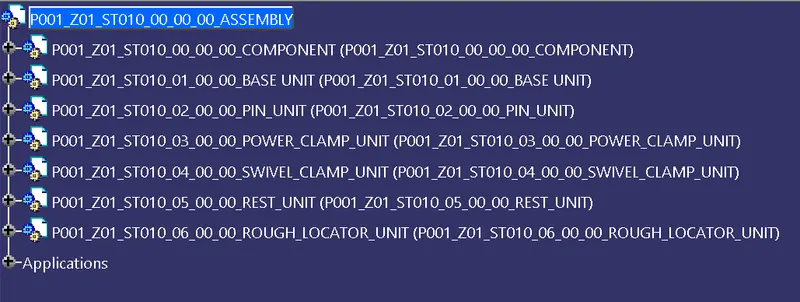
Feature Tree
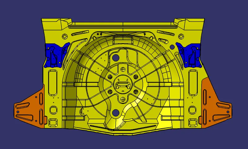
Car Panel
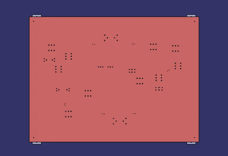
Base Unit
Pin Unit
Power Clamp Unit
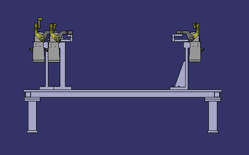
Swivel Clamp Unit
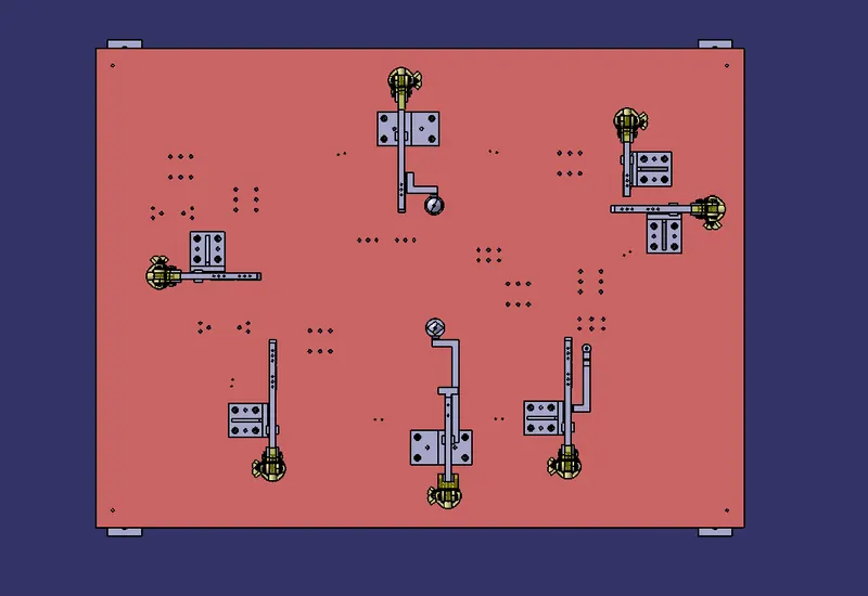
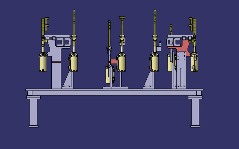
Rest Unit
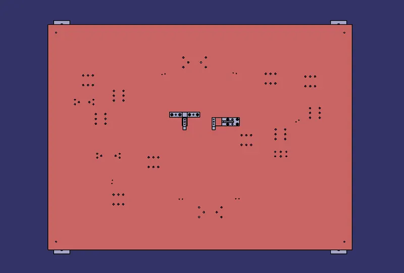
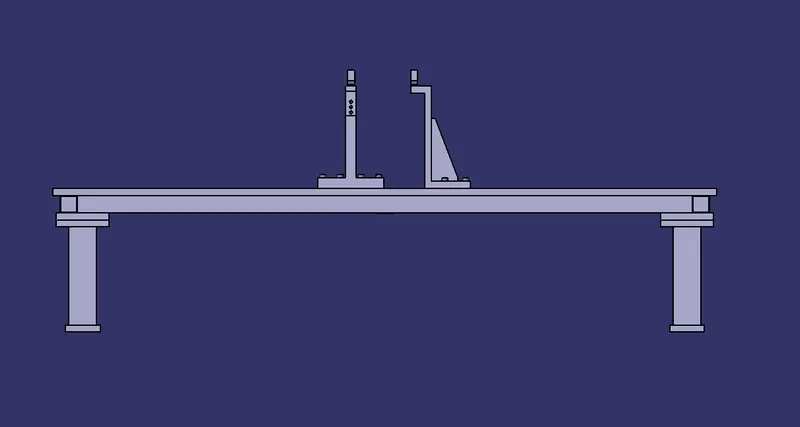
Rough Locator Unit
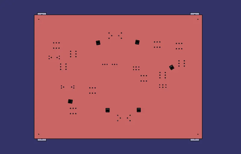
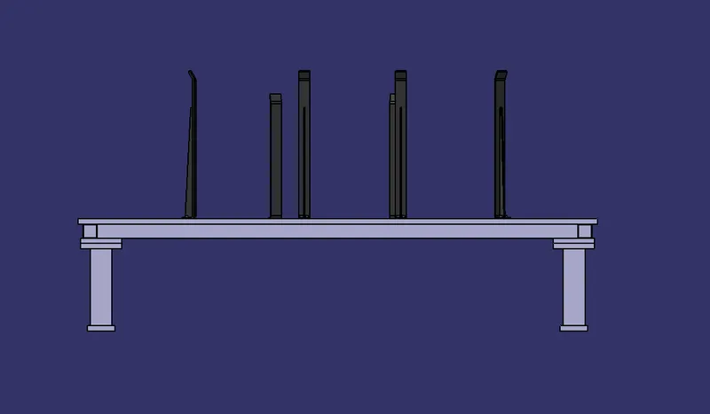
Assembly
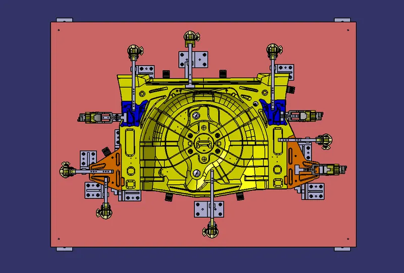
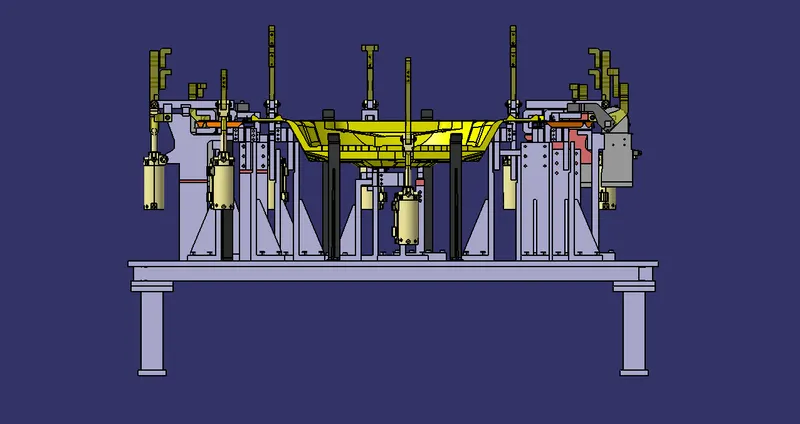
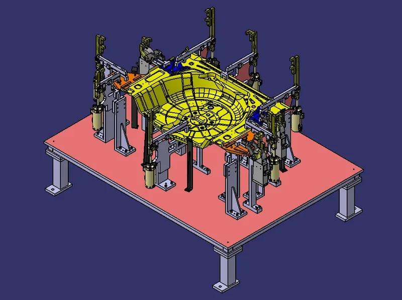
Nominality Check
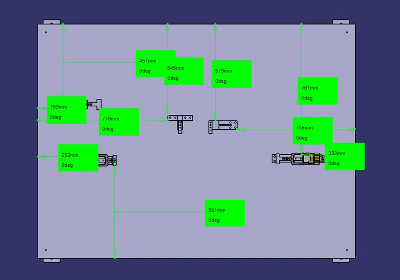
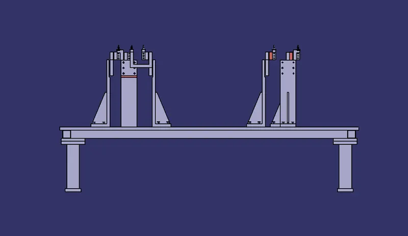
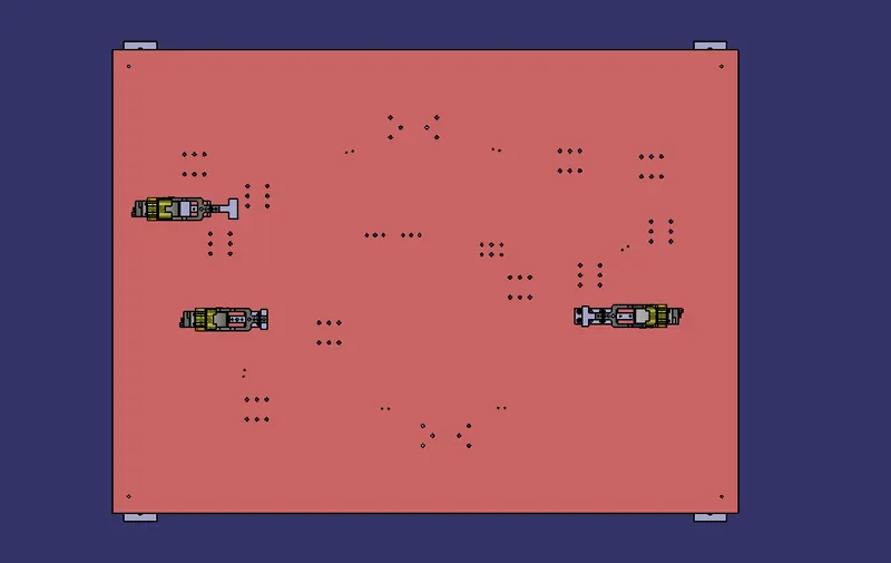
- The Rough Locator unit was created with proper design methodologies.
- The 3D finishing process was performed with atmost perfection.
- Necessary images and part files were attached.