Introduction to BIW and Fixtures Challenge
AIM:
To study about the various design aspects regarding BIW fixtures.
OBJECTIVE :
- To define what is BIW and brief about its parts.
- To explain about BIW nomenclature.
- To elaborate on Fixtures and its types.
- To state the basic principle of fixture design.
- To elaborate the different types of BIW Stationstypes of BIW Stations.
- To list out the basic terminologies used in the BIW fixtures.
1. Body-In-White (BIW)
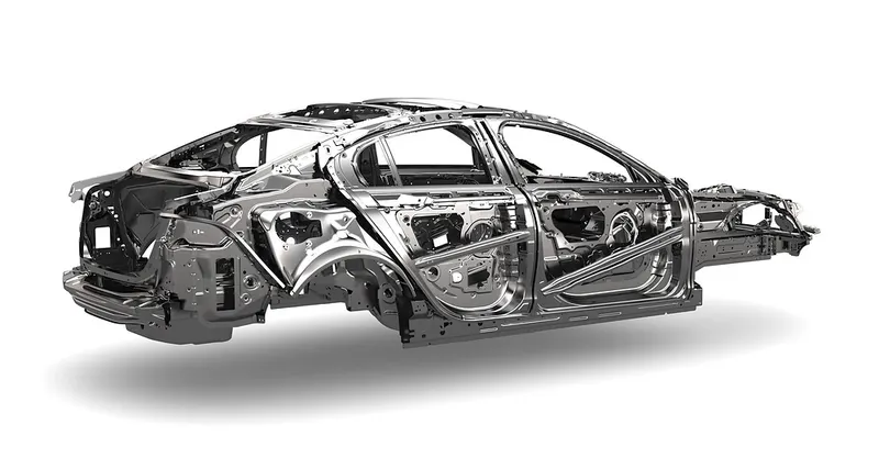
Body in white (BIW) is the stage in automobile manufacturing in which a car body's frame has been joined together, that is before painting and before the motor, chassis sub-assemblies, or trim have been integrated into the structure. Assembly involves different techniques such as welding (spot, MIG/MAG), riveting, clinching and bonding.
In car design, the BIW phase is where the final contours of the car body are worked out, in preparation for the ordering of the expensive production stamping die. Extensive computer simulations of crash-worthiness, manufacturability, and automotive aerodynamics are required before a clay model from the design studio can be converted into a body in white ready for production.
The name 'Body in White" is due to the fact that the entire welded body which is obtained as a result of roof, doors, cross members and pillars is eventually dipped into a greyish-white primer. Thus it got its name as Body in White. It forms the skeleton of an Automobile.
BIW can be categorized as follows,
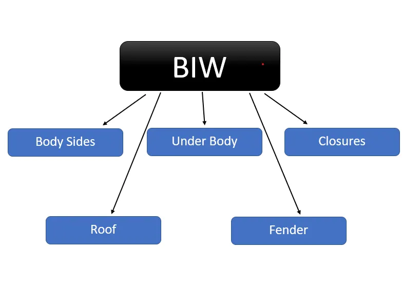
Body Sides
Body sides can be classified as,
- Body side Outer
- Body side Inner
It generally refers to the either sides of the cars which includes the A,B and C pillars.
Under Body
Under body can be classified as,
- Front End Under Frame - It refers to the engine compartment which consist of the Engine and its surrounding components.
- Main Floor - This forms the base of the vehicle on which various features like the seats, steering and the IP will be located.
- Rear End Under Frame - This forms the rear end which corresponds to the boot space of the vehicle.
Closures
Closures can be classified as,
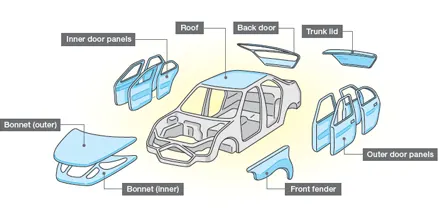
- Front Door - It is used to cover front openings on the either side of the vehicle.
- Rear Door - It is used to cover rear openings on the either side of the vehicle.
- Hood - It is used to cover the Engine compartment of the vehicle.
- Deck lid - It is used to cover the boot of the vehicle.
Roof
Roof can be classified as,
- Roof Inner
- Roof Outer
It refers to the top surface of the vehicle.
Fender
- Fender is the curved portion of the car's body that sits over and houses the wheels.
- It is present on the either side of the vehicle at the front as well as back.
2. BIW Nomenclature
BIW Nomenclature is the defined as the process of naming a part or component.
BIW fixtrues has its own set of nomenclature.
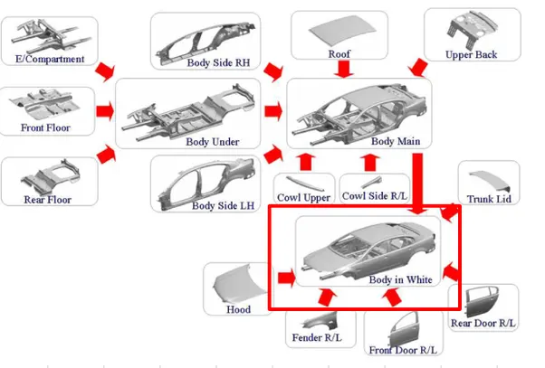
These nomenclature differ for different parts of the world.
For example a component which is known as Bonnet in UK description is known differently as Hood in US description.
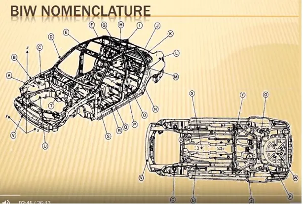
| ITEM | UK Description | US Description |
| A | Inner wing pannel | Motor compartment side panel |
| B | Upper wing member | Motor compartment upper rail |
| C | Suspension tower | Shock tower |
| D | Upper A-Pillar | A-Pillar ot Windshield pillar |
| E | Windscreen header rail | Windshield header or Front header |
| F | Roof stiffner | Roof bow |
| G | Rear parcel tray | Package shelf |
| H | Cantrail | Side roof rail |
| I | Backlight frame | Backlite headder or Rear header |
| J | C-Pillar | C-Pillar |
| K | D-Pillar | D-Pillar |
| L | Rear qyarter panel | Rear quarter panel |
| M | Boot flooer panel | Rear compartment panel |
| N | Rear setback ring | Rear seatback opening frame |
| O | Rear seat panel | Rear seatback panel |
| P | B-Pillar | B-Pillar or Center Pillar |
| Q | Floor Panel | Floor panel |
| R | Sill | Rocker or Rocker panel |
| S | Lower A-Pillar | Front body hinge pillar |
| T | Das panel | Dash panel |
| U | Engine rail | Motor compartment lower rail |
| V | Front bumper | Front bumper |
| W | Spare wheel well | Spare tire well |
| X | Centre tunnel | Tunnel |
| Y | Rear seat cross-beam | #4 Crossbar |
| Z | Rear suspension support beam | #5 Crossbar |
3. BIW Fixtures
- Fixtures are something which are held securely, usually permanently, attached or appended to a desired location according to the application of a particular component.
- Here fixtures are used to hold the components which are to be processed.
- Fixtures must be in such a way that the vibrations must be minimal to the adjacent components and to ensure an easy handling during the machining process.
- Fixtures are designed using the 3-2-1 principle.
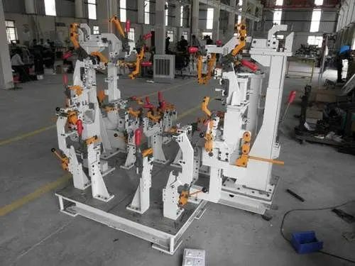
The various types of fixtures are as follows,
- Production Fixtures
- Pre-Production Operation Fixtures
- Checking Fixtures
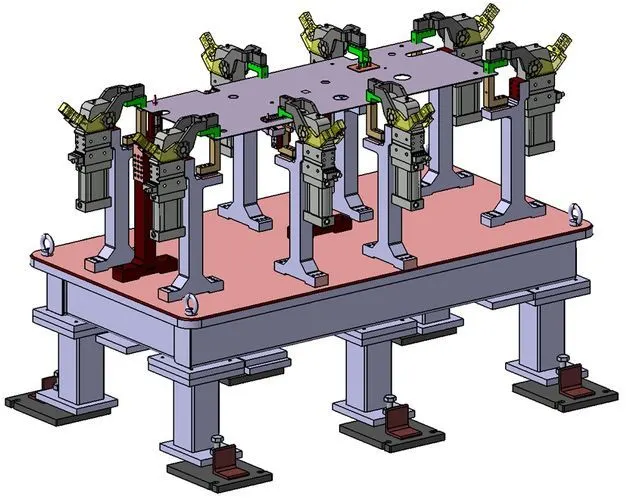
Production Fixtures
- Production fixtures are generally used in case of mass production.
- It is the fixture from where the vehicle will be assembled together to form the end product and it reaches the customer.
- Thus the hadrness, quallity, tolerances and its aesthetics of the fixture must be tested.
- It should be easily accessible for maintenance purposes.
Pre-Production Operation Fixtures
- Pre-Production fixtures generally serves as a prototype to the production fixtures.
- It is used for initial batch production to study the feasibility.
- Any errors in the pre production fixtures can be rectified in the upcoming fixtures.
- These fixtures are not widely used in order to minimize the overall production cost of the vehicle.
Checking Fixtures
- Checking fixtures are used for inspection purposes which are similar to Geo fixtures.
- Tolerences are to be accounted for in these fixtures.
- It does not involve any kind of processing.
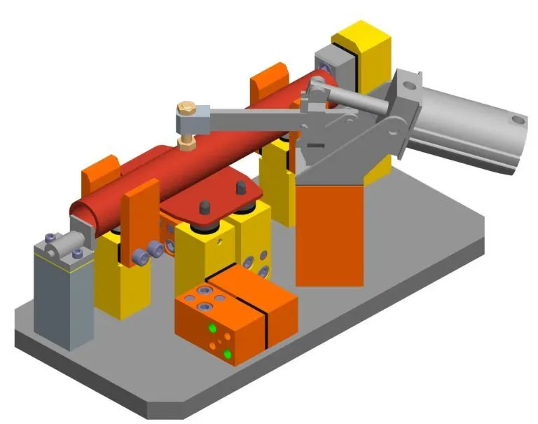
4. Principle of Fixture Design
- The major time in designing a fixture is spent in locating the workpiece in that fixture.
- The workpiece must be positioned in such a way that all of its Degree of Freedom must be arrested.
- Degree of Freedom is the number of control variables available for a component to initiate its motion.
- Thus fixtures are designed using the 3-2-1 principle.
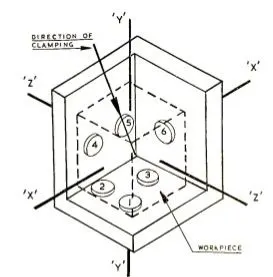
3-2-1 Principle
- The 3-2-1 method is a work-holding principle where three pins are located on the 1st principle plane, i.e., either XY, YZ, ZX. And two pins are located on the 2nd plane perpendicular to the 1st plane, and at last, one pin on the plane is mutually perpendicular to the 1st and 2nd planes.
- It represents the minimum requirement for the locating elements.
- The locators along with the clams which hold the part in place, provides equilibrium for all the forces.
- Stability is satisfactory if all three rest buttons are widely spaced and resultand cutting force lies within the triangular area between the buttons.
- If resultant cutting force lies outside the triangular area then it generates a moment which in turn lifts are overturns the component.
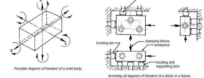
Degrees of Freedom
There are 12 degree of freedom of a work piece, movement about negative and positive axis and clockwise and anti-clockwise rotation about the three axis.
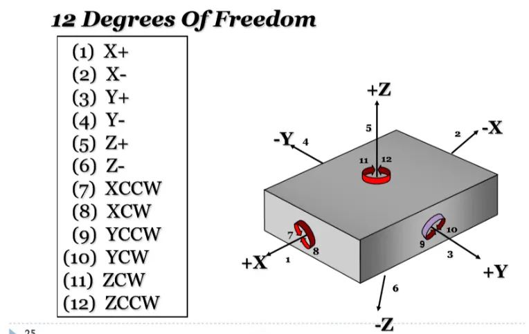
There are 6 tanslational degrees of freedom +X, -X, +Y, -Y, +Z, -Z,
6 rotational degrees of freedom which are
- Clockwise around X axis (CROT-X)
- Anticlockwise around X axis (ACROT-X)
- Clockwise around Y axis (CROT-Y)
- Anticlockwise around Y axis (ACROT-Y)
- Clockwise around Z axis (CROT-Z)
- Anticlockwise around Z axis (ACROT-Z)
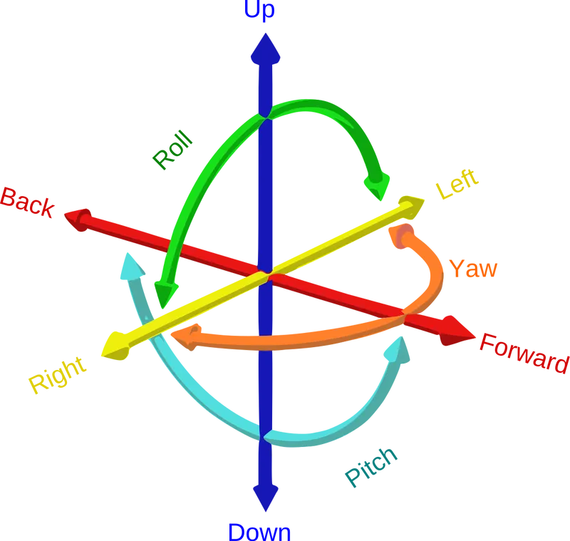
We must fix all the 12 degrees of freedom except the three transitional degrees of freedom (-X, -Y and -Z) in order to locate the work piece in the fixture. So, 9 degrees of freedom of the work piece need to be fixed.
The jig and fixture are tools used for holding the work piece in a correct location for mass production. Various types of fixtures (like drilling fixtures, milling fixtures, and welding fixtures) are used in industry. The 3-2-1 method is the fundamental principle for all types of fixture design.
5. BIW Stations
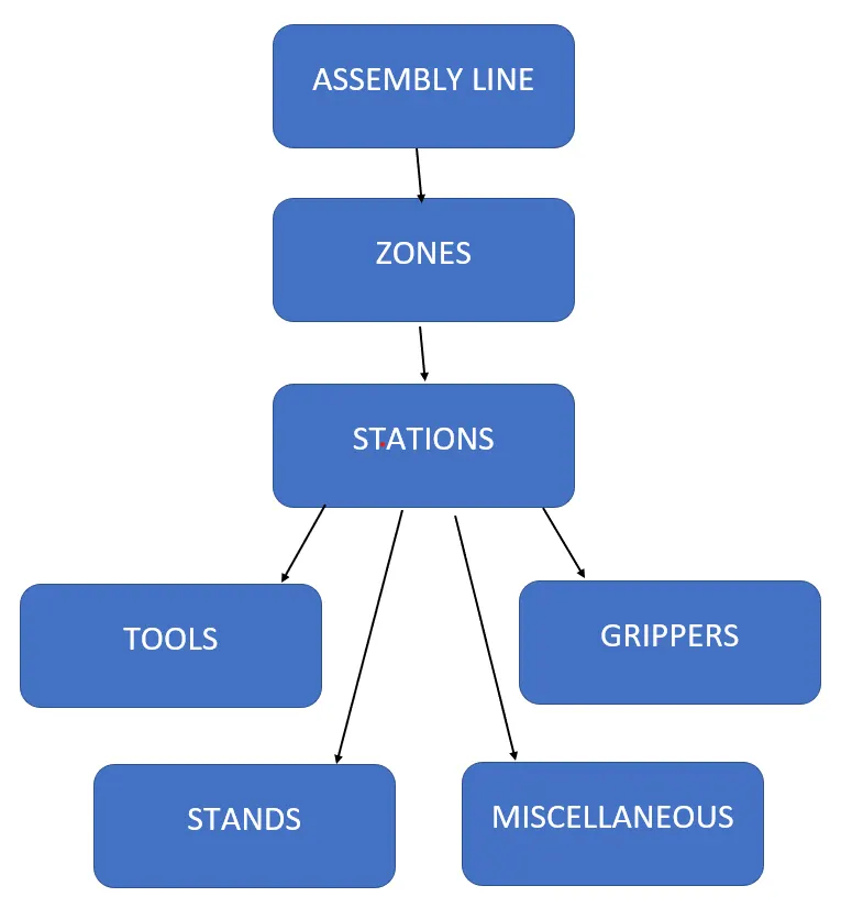
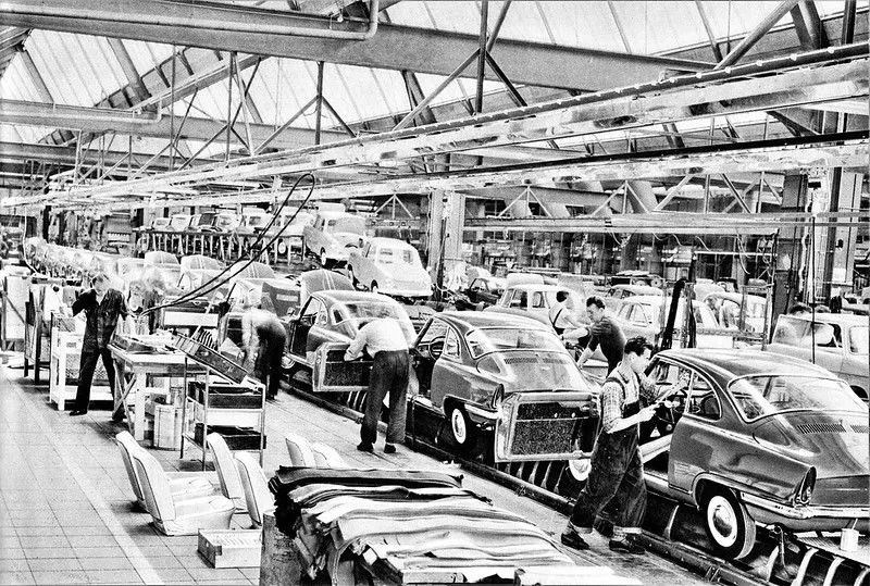
- An assembly line is a process in which car panel/car body parts are joined as the semi finished assembly moves from one station to another station until the final product is produced.
- In the process of joining in assembly line , panels are moved from one section to another sections.Those sections are called Station.
In BIW fixture designing we have various stations which are used to locate the panels so that joining processes can be done.
Some of these stations are as follows
- Geo Station
- Respot Station
- Pedestal Weld/Rivet
- Loading Station
- Buffer Station
- Marriage station
- Sealing station
- Curing station
Geo Station
In this station geometry of two parts are fixed. it can be either using welding or riveting . In this station precision and geomatry of the finished product is defined Locating pins have closer tolerence of 0/-0.15.
Diameter of locating pins should be lesser than the panel hole dia. So Tolrence in locating pin is given in negative value.
Respot Station
Once product comes out of the Geo Station and there are left out spots where spot welding or riveting is to be done, it is moved to another station.
This station is called Re-spot station.
These left out spots may be the due to clamp plan, cycle time,robot reach ability or any other various reasons.
Checking Station
A Checking station is the place where all the features such as positioning, tolerances, relative dimensions of a component is checked.
A CMM machine is employed to check these parameters and gives a proper report with respect to the nominal values.
Pedestal Weld/Rivet
In this station , Pedestal gun is mounted on a tool and panel is manipulated manually or by robot to weld the panels.
Pedestal station is generally a Re spot station.
Re spot station and Pedestal station, both perform same kind of operation . but to decide whether to go for pedestal or a re-spot station some parameters needs to consider like cycle time, floor space, no. of welds, clamp plan, or size of the panel.
Loading Station
This station is used for loading of panel and same station is used to change the orientation of the if it is required in the upcomin station.
Sometime this station is used when Robots are unable to transfer panel from one station to another.
Buffer Station
This station is used to make the balance between the process.
Some stations carry out procees in lesser time as compared to their respective stations.In that case panels can be stored in one sation so that assembly line process remains smooth.
Marriage station
In this Station inner and outer panels are joined.
In this station to avoid the imprssion on the outer panel(A class surface), copper strips are used in betweenn the weld tip and A-class surface.
Sealing station
In this station Sealant application is carried out.T
his process can be carried out manually or by using robots. Sealer is used in between two panels so that panels do not flatter due to friction.
Curing station
In this Station product recieved after sealing application, is kept idle at ambient temperature, which allows sealent to get dry with better bonding between the panel.
Gripper
A Gripper is a device which is used the hold the component which is to be machined.
It is also known as End of Arm Tooling (EOAT)
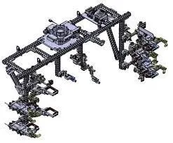
The various types of Grippers are as follows,
- Material Handling Gripper - It is generally used to handle the component from one station to another station.
- Process Gripper - It does the same job like MH Gripper but in addition to that it performs various operations such as welding, riveting, gluing and sealing.
- Combo Gripper - It performs the same activity as the other gripper along with a weld gun which is used for welding purposes.
- Dual Gripper - It also is similar to the other grippers but it is a two sided gripper.
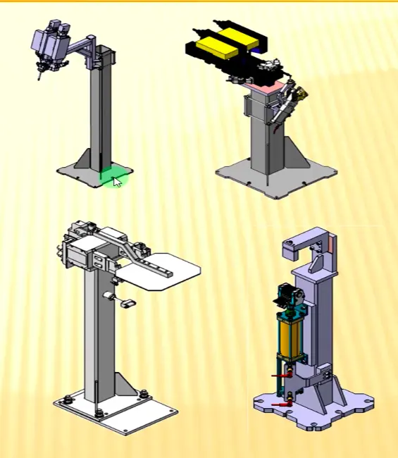
Stands
Stands are used to act as supports for various processes.
The different types of stands are as follows,
- Gluing and sealing stand
- Docking stand
- Date stamp stand
- Pedestal gun stand
The other components of BIW stations include,
- Buffer storage
- Take out trolley
- Conveyor tools
6. Basic terminologies used in the BIW fixtures
The Basic terminologies used in BIW fixture design are as follows,
- Principle Locating Points
- Mylar
- Pin
- Blade
- L Block
- Pin Block
- Riser
- Weldment
Principle Locating Points (POP)
- These locating points are used to define the location of a component in a precise manner.
- POP's are generally defined in the drawing.
Mylar
- MYLAR is one kind of block that touches the panel and holds or clamps the panel.
- Mylars are always designed in CAR LINE. Mylar is also called NC Block.
- Mylars are mounted on any block or plate with Shimming, So that height of mylar can be adjusted accordingly at the assembly level.
- For ‘A’ class surfaces Nylon mylars are used in order to save them from scratches.
Pin
- Pins are used to locking the rotational movement of the panel.
- Generally there two types of Pins, one is Round Pin and another one is a Diamond pin.
- Generally we use two and three-directional shimming for pins.
Blade
- The plate which connects Riser to the Clamp cylinder is named Blade.
- This plate plays an important role in building the unit.
- The plate can be of any shape but the plate should be as compact as possible.
L Block
- A plate shaped as L is called an L block.
- This part is used as a connection between mylar and Blade.
- Generally L blocks are used to provide shimming.
- It is not necessary that L blocks are only used for shimming, its uses changes as per the requirements, At some places, it is used just to connect one part to another.
Pin Block
- Pin Block is also called Pin Retainer.
- This block holds the pin and restricts the rotational motion of the pin.
Riser
- The part which is mounted on the base plate and holds a clamp or pin cylinder on it, is called Riser.
- Riser can be Standard Part or manufactured part, it varies from project to project.
- A riser can be a Single part or welded part.
Weldment
- Weldment is the assembly of two or more parts that are joined by welding.
- A weldment is made with a thumb rule to have a 5 mm overlay on each other plates so that space can be provided for welding.
CONCLUSION :
All the given objectives were satisfied with atmost perfection.
The images were attached wherever necessary.