Photo Realistic Rendering
AIM :
To create and assemble various parts of an American Chopper and obtain their photorealistic rendered images using SOLIDWORKS
INTRODUCTION :
The American Chopper comprises of various parts which were created individually. These individual parts were finally put together by means of a proper assembly.
The various components involved in the design of an American Chopper were,
- Transmission belt
- Kick stand
- Front fender
- Rear fender
- Chain
- Oil tank
- Pedal
- Front wheel
- Rear wheel
- Front fork
- Chassis
- Engine
- Gas tank
Each part has a unique way of applying the available functions and tools inoder to acheive the solid part. The level of difficulty increases to match the complexity of the parts.
TRANSMISSION BELT :
Transmission belt is a continuous looping structure mad from a flexible material.
It is used in a vehicle to transfer the mechanical energy from the engine to the gears.
These belts are often roped over pulleys inoder to provide the effective transmission.
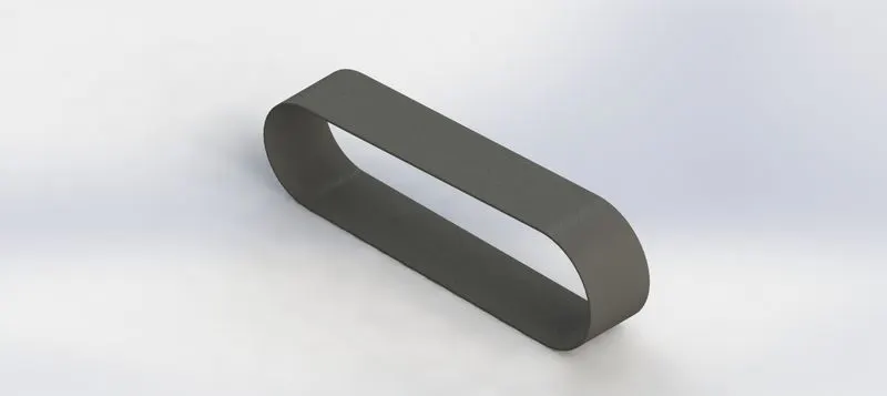
The various commands used were,
- 2D sketch
- Extrude boss/base
KICK STAND :
Kick stand is a small metal rod attached with a bike or a bicycle.
It is used to support the vehicle in a position when it is not in use.
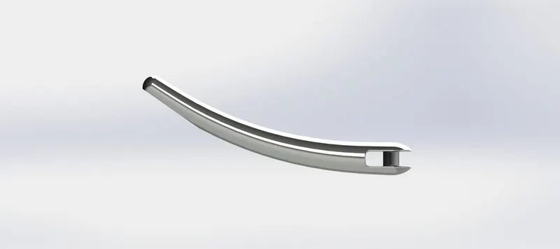
The various commands used were,
- 2D sketch
- Extrude boss/base
- Extrude/cut
- Fillet
- Lofted boss/base
- Split
- Dome
FENDERS:
Fenders are the components which acts as a protective cover fot thr wheels of a vehicle.
It keeps mud from spashing onto the vehicle from the wheels.
Vehicles consist of fenders on their front and back wheel.
FRONT FENDER : It is used for the front wheel.

The verious commands used were,
- 2D sketch
- Revolve boss/Base
- Split
- Fillet
REAR FENDER : It is used for the rear wheel.
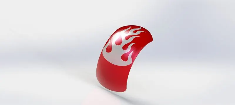
The various commands used were,
- 2D sketch
- Revolve boss/base
- Split
- Fillet
- Shell
CHAIN :
Chains play a significant role in transmitting the power from the Engine to the back wheel.
These chains must be properly lubricated inoder to have a smooth transmission.
Unlubricated chains may cause in decreased efficiency.
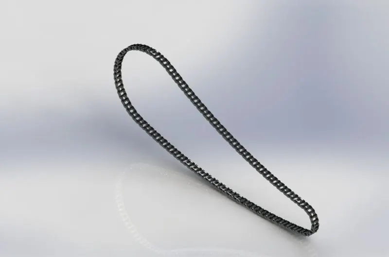
The various commands used were,
- 2D sketch
- Extrude boss/base
- Blocks
- Fillet
- Pattern
- Mirror
OIL TANK :
Oil tank is a storage unit which is used for storing Oil.
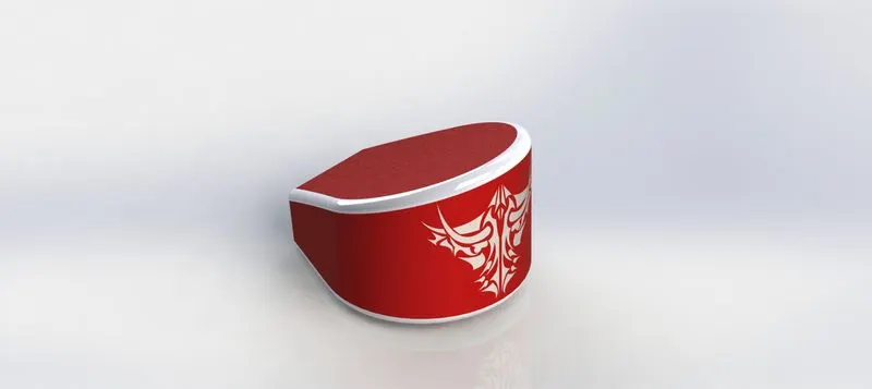
The various commands used were,
- 2D sketch
- Extrude boss/base
- Fillet
- Shell
- Combine
PEDAL :
A Pedal is a foot lever structure which is used in a vehicle inoder to activate a mechanism.
Pedals are generallly used for shifting gears and braking.
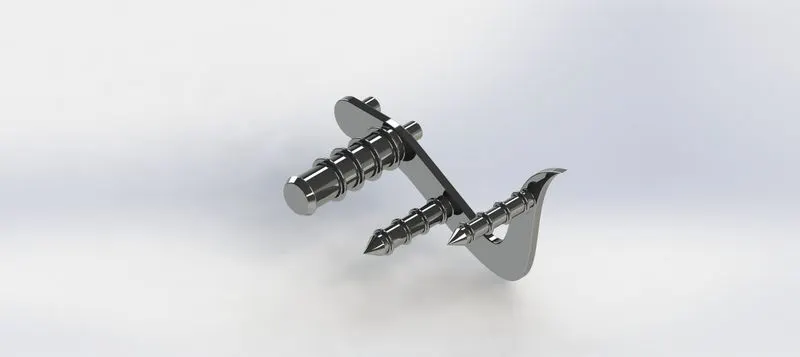
A mirrored pedal named PedalLH was also used.
The various commands used were,
- 2D sketch
- Extrude boss/base
- Revolve boss/base
- Fillet
- Pattern
- Chamfer
WHEELS :
Wheels are one of the important parts of a vehicle which involves in the locomotion of the vehicle.
It is a circular object that is mounted on an axle which is able to rotate.
A wheel converts rotatory potion to linear motion in a vehicle.
FRONT WHEEL : It is loctaed at the front of the vehicle.
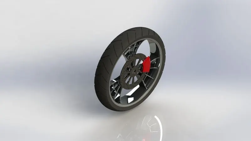
The various commands used were,
- 2D sketch
- Extrude boss/base
- Revolve boss/base
- Extrude cut
- Revolve cut
- Fillet
- Chamfer
- Combine
- Pattern
REAR WHEEL : It is located at the back of the vehicle to which the chain is connected.
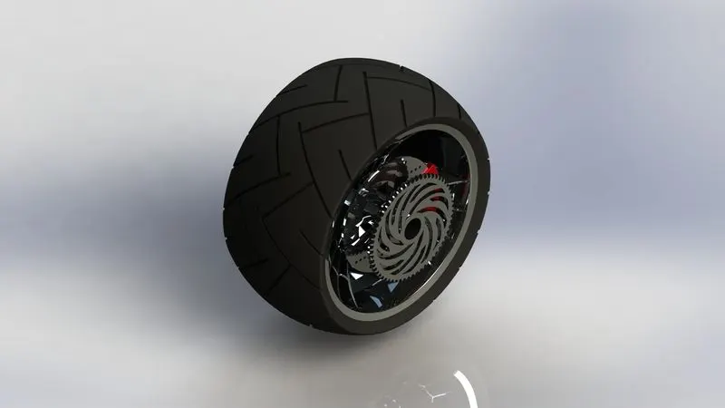
The various commands used were,
- 2D sketch
- Extrude boss/base
- Revolve boss/base
- Extrude cut
- Revolve cut
- Fillet
- Chamfer
- Combine
- Pattern
FRONT FORK :
Fork acts as the suspension for a vehicle which is attached to the front tyre.
It consists of the handle bar of the vehicle which is used to control the direction of the vehicle motion.
Forks are the shock absorbers of a vehicle.
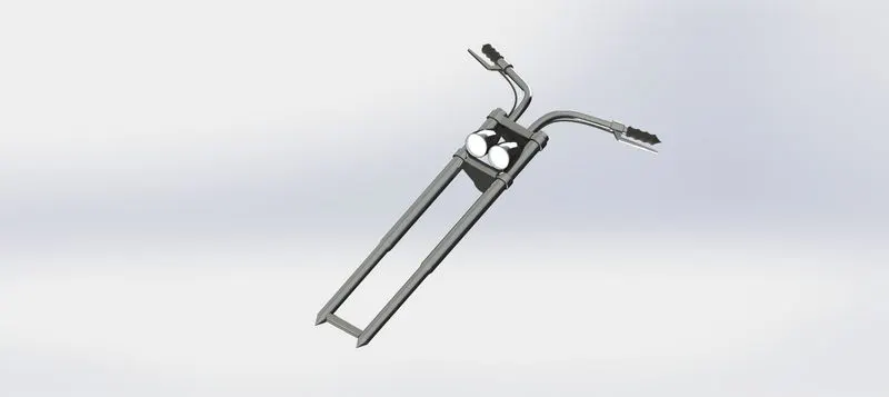
The various commands used were,
- 2D sketch
- Extrude boss/base
- Revolve boss/base
- Sewpt boss/base
- Extrude cut
- Revolve cut
- Combine
- Fillet
- Chamfer
- Dome
- Body-Move/Copy
- Projected curve
- Pattern
CHASSIS :
Chassis forms the entire frame of a vehicle on which the vehicle body is mounted.
All the parts are attached with the chassis inoder to functon as a vehicle.
The chassis provides the shape and structure of a vehicle.
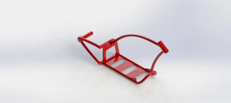
The commands used were,
- 2D sketch
- Extrude boss/base
- Revolve boss/base
- Sewpt boss/base
- Extrude cut
- Split
- Combine
- Fillet
- Projected curve
- Dome
ENGINE :
A motorcycle engine is an engine that powers a motorcycle.
Motorcycle engines are typically two-stroke or four-stroke internal combustion engines, but other engine types, such as Wankels and electric motors, have been used.
Most engines have a gearbox with up to six ratios.
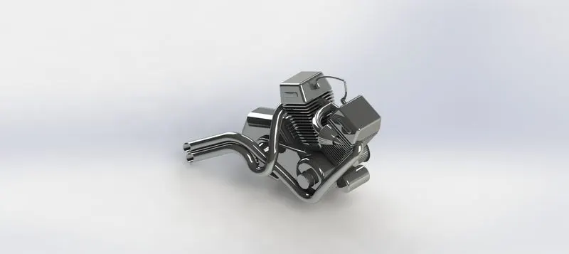
The various commands used were,
- 2D sketch
- Extrude boss/base
- Revolve boss/base
- Sewpt boss/base
- Extrude cut
- Revolve cut
- Combine
- Fillet
- Chamfer
- Dome
- Body-Move/Copy
- Projected curve
- Composite curve
- Pattern
GAS TANK :
fuel tank (also called a petrol tank or gas tank) is a safe container for flammable fluids.
Though any storage tank for fuel may be so called, the term is typically applied to part of an engine system in which the fuel is stored and propelled (fuel pump) or released (pressurized gas) into an engine.
Fuel tanks range in size and complexity from the small plastic tank of a butane lighter to the multi-chambered cryogenic Space Shuttle external tank.
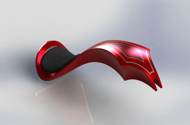
The various commands used were,
- 2D sketch
- Extrude surface
- Swept surface
- Lofted surface
- Boundary surface
- Projected curve
- Knit surface
- Swept cut
- Mirrot
- Split line
- Surface trim
- Shell
ASSEMBLY :
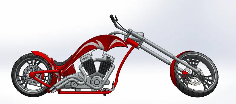
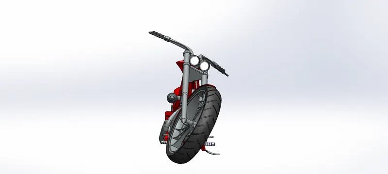
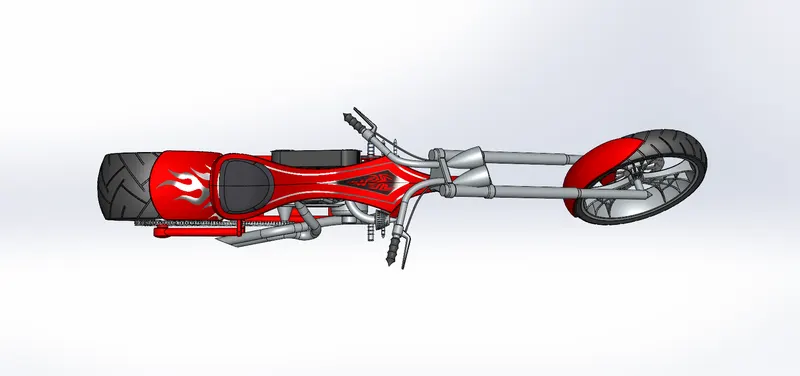
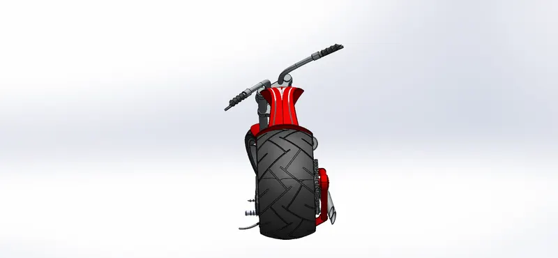
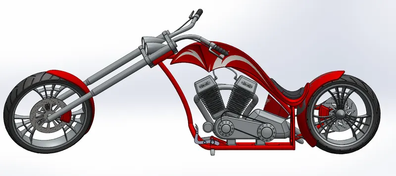
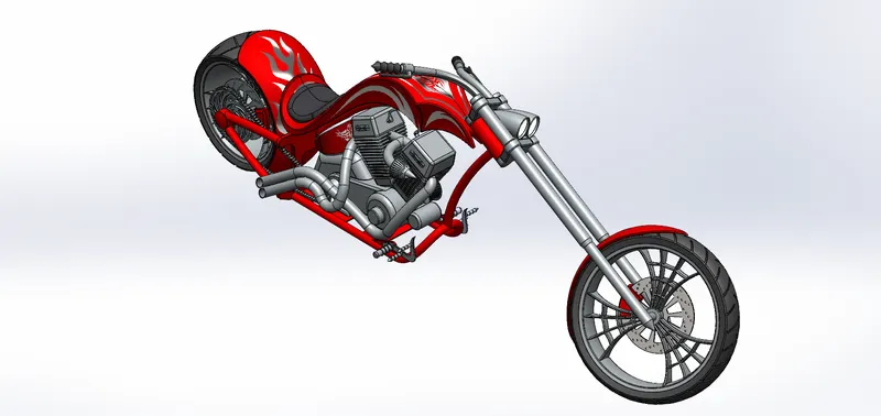
Alll the individual parts were inserted in to the assembly in a sequential manner.
Proper mating conditions were given to each of the parts in the assembly by considering the Chassis as the reference.
Thus all the parts move only with respect to the chassis and they stay intact.
The different views of the American Chopper were listed below,
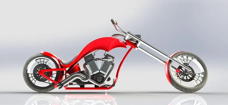
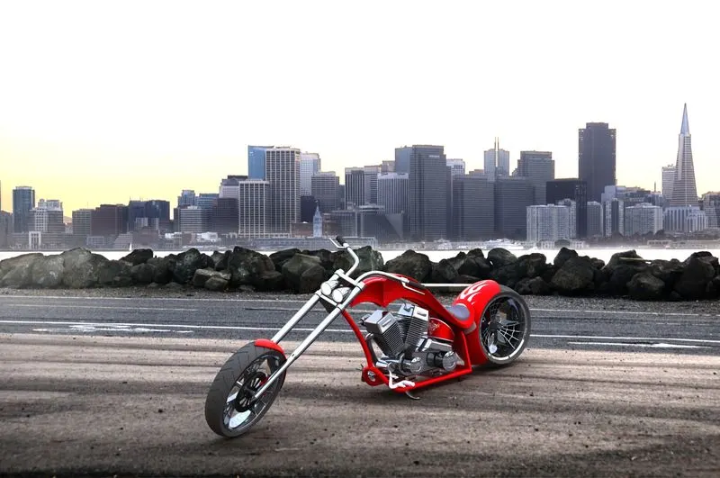
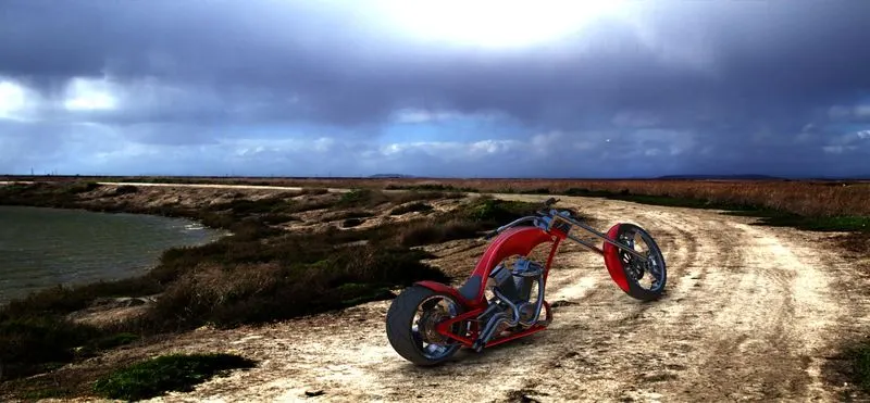
RENDERED IMAGES OF AMERICAN CHOPPER :
CONCLUSION :
- All the individual parts of the Chopper were designed precisely.
- The Assembly of the Chopper was made successfully using all the designed components.
- The photo-realistic rendered images of the assembly were simulated.