Base Unit Design
AIM :
To study about the various design aspects regarding BIW fixtures.
OBJECTIVE :
- To explain about Base unit.
- To list out the points need to consider while designing a Base unit.
- To explain about the Dump Unit.
- To list out the points need to consider while designing a Dump unit.
- To explain about the Slide Unit.
- To list out the points need to consider while designing a Slide unit.
1. BASE UNIT
Base Unit is one of the most significant unit of the fixture design because the entire fixture assebmly is mounted over it.
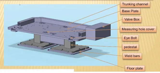
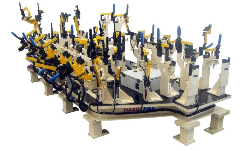
The various parts of a Base Unit are,
- Base Plate
- Pedestal
- Trucking channel
- Valve box
- Eye bolt
- Floor plate
- Weld bar
Base Plate
- Base plate is a machined plate of 25 to 40 mm thickness.
- It is generally made up of steel and aluminium.
- The various units such as clamp unit, pin unit etc., are mounted on the base plate using drilled holes.
- A base plate should cover all the units with its outer periphery including opening.
- Datum holes must be covered using cover plates.
Pedestal
-
A pedestal is a part which connects the base plate to the floor plate.
-
In general a pedestal is a standard part and in some cases it can be a welded frame integrated with the base plate.
-
A standard pedestal can be of different height and different sizes.
-
Depends on the size of the base plate, the number of pedestal varies for load distribution.
-
A pedestal are of different types with different inclinations.
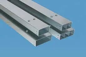
Trunking channel
-
A trunking channel is a duct which accommodates all the pneumatic and electrical hoses and wires for the units of the tool.
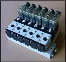
Valve box
- Valve box is a standard part which will accommodates the pneumatic valves for the units.
Eye bolt
-
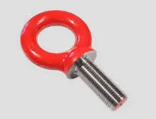
Eye bolts are used for the transporting of the tool from one plate to another.
-
This can be done using lift hooks, fork lift holes will also be provided in some cases for transporting purpose.
Floor plate
- Floor plate is grouned to the floor with fixed bolt on the ground.
- These plates are also called as foundation plates.
-
There will be a clearance of 10mm maintained between the pedestal base plate and the floor plate.
-
This clearance will be used by the levelling screws, for levelling the entire tool.
Weld bar
- Weld bars are be used to weld the positions permanently , after levelling is done.
- A weld bar is a plate along the sides of the base plate of the pedestal.
2. DESIGN ASPECTS OF A BASE UNIT
The various points that has to be considered while designing a Base Unit are,
Working height
- Working height is an important aspect while designing a base unit.
- It generally depends on the nature of welding.
- A working height of 850 to 1100 mm is considered for a manual fixture which actually depends on the country.
- If the base plate has a tubular structure, the working height may increase by 100 to 250 mm.
- Andditional leg structure may be provided to reach an adequate working height.
Size of the Base plate
- Size of the base plate must be known for the design purposes.
- It is useful during fabrication process and it improves the overall handling.
- Proper flattening of the base plate must be ensured when the base plate is very long.
Eye bolts for the assembly are selected by considering the weight of the enitre assembly.
Its location also needs to be taken care of depending on the tyo of hooks or belts used in order to ensure that there is no damage to the adjacent parts in the asembly.
Depending on the size and weight of the assembly, fabricated plate can be used or a normal plate can be used when there is no such requirements.
3. DUMP UNIT
Dump Unit is similar to fixed pin unit which is used in case of intricate arrangements of the fixtures.
When the panels are hard to reach, fixed pin units are difficult to install during this situation Dump units are used.
Dump unit can have more than one cylinder to perform such a process.
The first cylinder dumps the assembly carrying clamp mylar, pins and retainers.
The panel must be easy to remove in the open position.
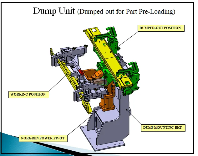
The various functions of Dump unit are,
- To fix the panel properly and ensure that its motion is restricted.
- To ensure that there is enough clamping force in the cylinder to with stand the welding process.
- Proper shimming must me provided to the panel.
- The rotation of the panel is restricted using side blocks or magnets.
4. DESIGN ASPECTS OF A DUMP UNIT
The various points that has to be considered while designing a Dump unit are,
- 3-2-1 principle
- Mass of the assembly
- Opening and Closing time
- Cylinder validation
- Open position
3-2-1 principle
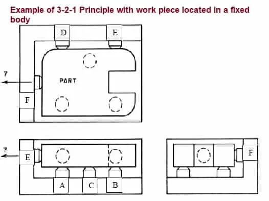
- The 3-2-1 method is a work-holding principle where three pins are located on the 1st principle plane, i.e., either XY, YZ, ZX. And two pins are located on the 2nd plane perpendicular to the 1st plane, and at last, one pin on the plane is mutually perpendicular to the 1st and 2nd planes.
- It represents the minimum requirement for the locating elements.
- The locators along with the clams which hold the part in place, provides equilibrium for all the forces.
- Stability is satisfactory if all three rest buttons are widely spaced and resultand cutting force lies within the triangular area between the buttons.
- If resultant cutting force lies outside the triangular area then it generates a moment which in turn lifts are overturns the component.
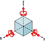
Locating Process in 3-2-1 method
We have two objectives when mounting a part in a fixture for machining
1. Accurately position the part at the desired coordinates.
2. Restrict all six degrees of freedom so that the part cannot move.
A widely used method of accomplishing these two objectives uses the 3-2-1 principle, so-called because it entails three steps that employ three, then two, then one fixed points of known location. Since that adds up to six fixed points, it’s also known as the six point method.
In the three steps of the 3-2-1 method, three mutually perpendicular planes, called datum planes, are introduced, one at each step. These three planes define the workpiece position, and together with opposing clamping forces fully constrain the part. Let’s take a look at the details of the 3-2-1 method
Mass of the assembly
- The Weight of the assembly which is dumped must be maintained as low as possible inorder to save maximum material.
- Less weight of the component reduces the required force on the component.
Opening and Closing time
- Time of opening and closing must be kep as low as possible.
- This will depend upon the weight of the assembly and power of the cylinder being dumped.
- The idel time must be minimized.
Cylinder validation
- Cylinder validation makes sure that the cylinder is able to push the load for operation and pull it back once the operation is done.
- Necessary calculations are performed to ensure that the cylinder is able to withstand these loads.
Open position
- The open position consist of only the moving parts.
- It is important to ensure that the open position does not interfere with any of the components.
5. SLIDE UNIT
Slide Unit is a unit which is used to position various components.
It is used in the mounting of various units in the fixtures, weld gun etc.
During the operation, a particular unit is mounted n the slide unit and it is slides forward to reach the desired location.
Once the operation is performed, it slides back.
This sliding motion is achieved with the help of a cylinder.
It also consist of sensor unit and stopper blocks to regulate the sliding motion.
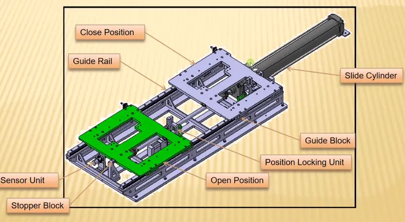
Slide units can be classified based on the following aspects,
- Based on type of Guide ways
- Based on type of prime mover
- Based on application
Based on type of Guide ways
Based on type of Guide ways it is further classified into,
- Hardened guide ways
- LM guide ways
Based on type of prime mover
Based on type of prime mover it is further classified into,
- Manual
- CNC
- Pneumatic
Based on application
Based on application it is further classified into,
- Horizontal
- Vertical
- Angular
6. DESIGN ASPECTS OF A SLIDE UNIT
The various points that has to be considered while designing a slide unit are,
- Weight carrying capacity
- Push and Pull forces
- Locking Mechanism
- Stopper blocks
- Sensor unit
- Stroke
- Open position
Weight carrying capacity
- The Load carrying capacity of the rail has to be calculated and checked in accordance with the weight of the assembly.
- Rails are chosen according to its weight carrying capacity.
Push and Pull forces
- It must be ensured that there is enough number of oush and pull forces for the sliding motion.
Locking Mechanism
- Locking mechanism is used to arrest the sliding motion.
- It ensures that the slider does not move at the open position.
Stopper blocks
- Stopper blocks are used for restricting the motion of the slider.
- Stoppers are provided to prevent the damage caused to the car panel.
Sensor unit
- Sensor unit is used to check the position of the slider.
- It is operated with the help of a push button.
- It senses the presence of any obstruction among the components and the slider is moved accordingly.
Stroke
- The length of the stroke must be checked according to the cylinder used.
- It ensures proper clearance areas.
Open position
- The open position consist of only the moving parts.
- It is important to ensure that the open position does not interfere with any of the components.
CONCLUSION :
All the given objectives were satisfied with atmost perfection.
Images were attached wherever necessary.