Attachment Feature Creation - Screw Boss & Dog House
AIM :
To create the Screw Boss and Dog House for the Centre Console Coin Holder.
OBJECTIVE :
- To make sure that the model meets the design rules for rib creation.
- To create the Tooling axis using bisecting method.
- To perform Draft analysis on the component.
SCREW BOSS :
- Bosses are commonly used for attacchment and assembly of plastic components.
- They are used to aid in the assembly of molded parts by providing a channel for a screw.
- Bosses must not merge into side walls as they may lead to the formation of sinks.
- Open bosses can be used near a standing wall.
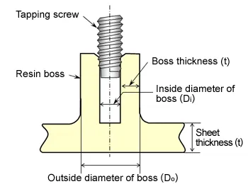
- The Boss thickness can be taken as 0.6 times the thickness of the component.
- A Draft of 0.5 degrees per side is the maximum limit.
- Height to Diameter ratio must be 3:1.
- Optimum fillet radius can be taken as 0.25 mm which is optional.
DOG HOUSE :
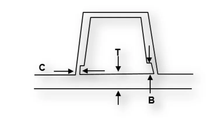
- Dog house is an engineering feature used in plastic trim design as supporting feature.
- A Draft of 1.5 degrees per side is the maximum limit.
- In case of a slide 3 degrees of Draft can be provided
- At the intersection part dog house wall thickness must me less than or equal to 40% of the wall thickness of the component.
- It's height should be between 3 and 6 mm.
PROCEDURE :
Creating Tooling Axis
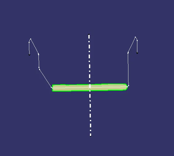
- Initially a base surface was extracted from the Class A to create a center point.
- An axis system was created upon this point.
- The Intersect feature was used to obtain a boundary of the Class A intersecting at the mid plane.
- Once the check for the discrepencies in the boundary is done, the Tooling axis was created from thr mid-point.
Creating Screw Boss feature
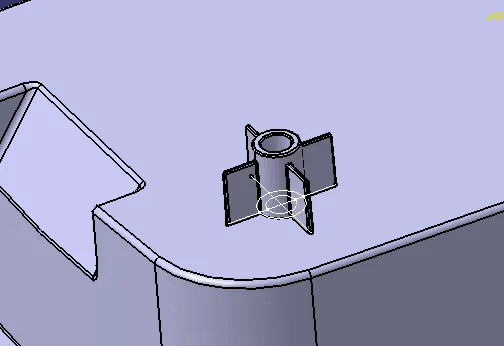
- Initially the base surface from the plastic component was extracted.
- A sketch for the rib was created on the surface consisting of a hole and a circle.
- This part was extruded upto a certain height.
- Another sketch was created for a boss.
- The boss was created using the Thicken feature in the pad command.
- The necessary drafts and fillets were created.
Creating Dog House feature
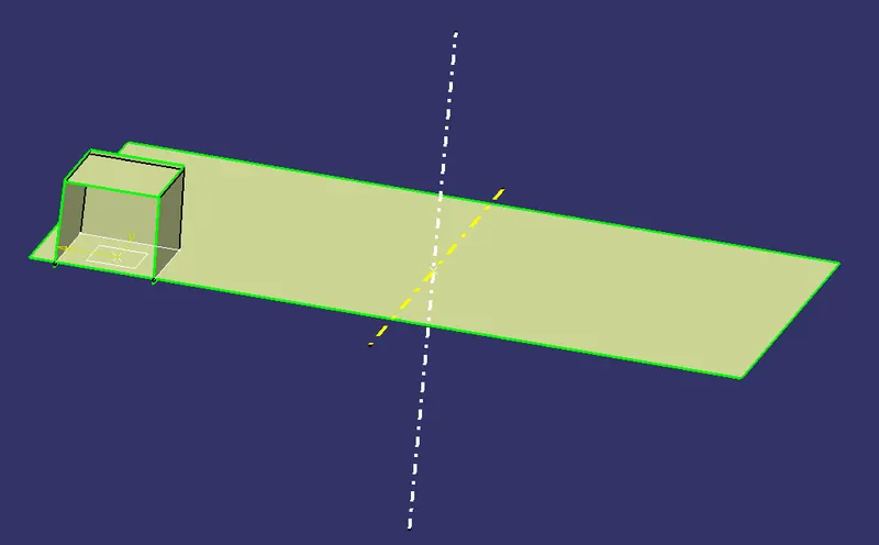
- Initially a sketch was created on the base which was extracted.
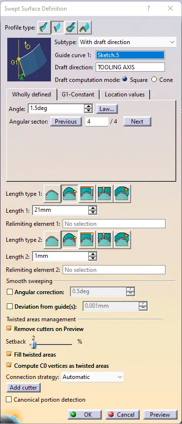
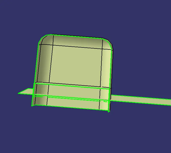
- The dog house outer profile was created using Sweep feature With draft direction alone the tooling axis with a draft angle of 1.5 degrees on the outside.
- An offsetted surface from the base was used to close the top portion of the dog house using Trim feature.
- The necessary fillets were provided to the surface.
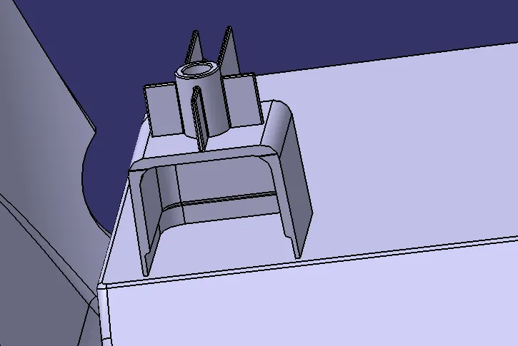
- An intersection part was created at the inner side of the dog house unit.
- A Draft of 0.5 degree wa given on the innerside of the dog house.
- A second tooling axis was created perpendicular to the main tooling axis in the Z direction inorder to accumulate the inner cavity of the dog house unit while machining.
- Another screw boss was added upon the dog house using the Translate feature.
Draft Analysis
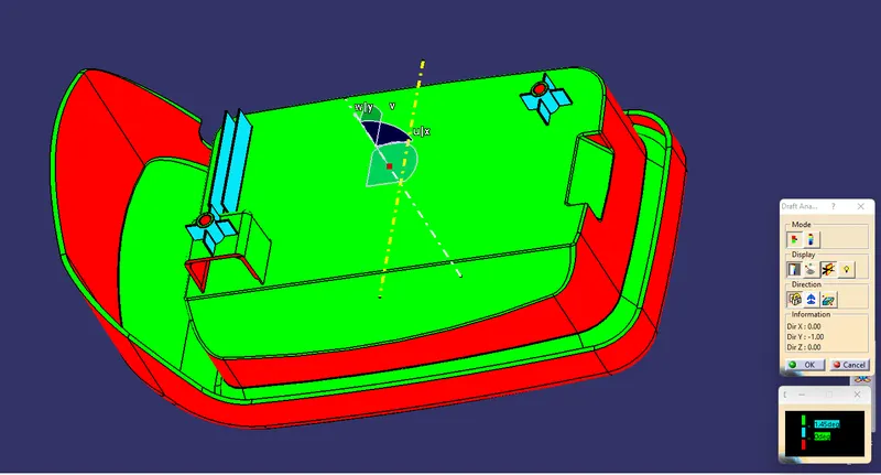
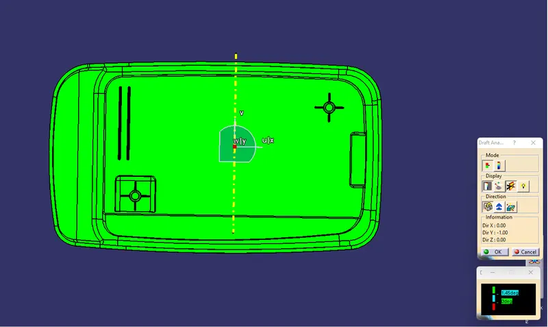
- The Drafting analysis was performed using the Feature Draft Analysis command.
- Using this command the compass was set on the main tooling axis and the Draft angle was changed to 1.45 degree.
MODEL RESULTS :
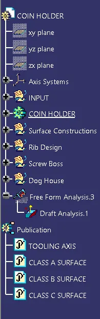
Feature tree
Front view
Top view
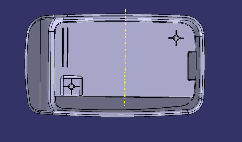
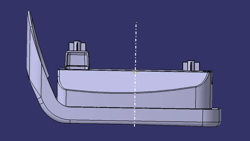
Side view
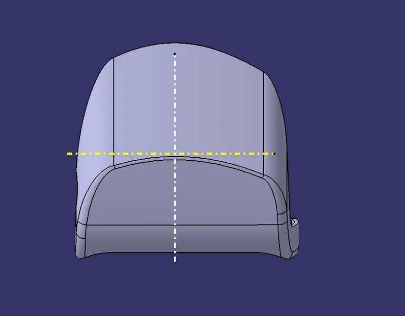
Isometric view
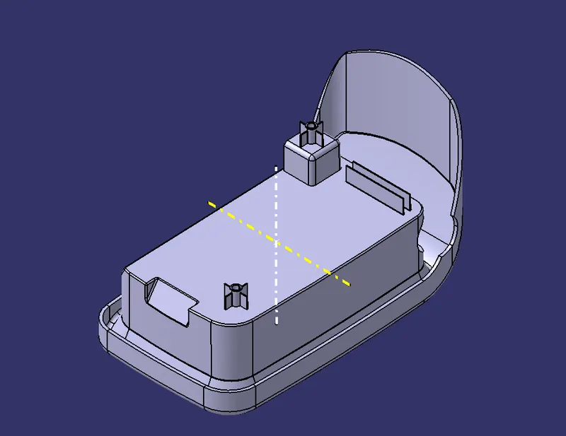
CONCLUSION :
- The creation of Tooling axis and Draft analysis were performed.
- The Screw boss and Dog house unit was created
- The necessary screenshots and files were attached.