B-Pillar Design with Engineering Features using Master Section Development
AIM :
To create a B-Pillar component with the B side features using the given Class A surface and the Master Sections.
OBJECTIVE :
- To make sure that the model meets the requirements of the draft angle.
- To create the Tooling axis and Lifter axis.
- To create the required Class B and Class C surfaces.
- To obtain a solid body from the surface using Close Surface feature.
- To perform Draft analysis on the finished component
- To create the required B side features.
B-PILLAR :
- The roof support pillar located in the car are named alphabetically by order of placement from front to back of the car.
- The B pillar is located at the midsection, between the A and C pillars.
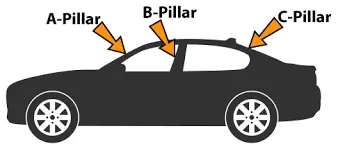
- B pillar is welded to the roof panel on top and the vehicle's floor pan at the bottom.
- This pillar provides structural support to the vehicle's roof.
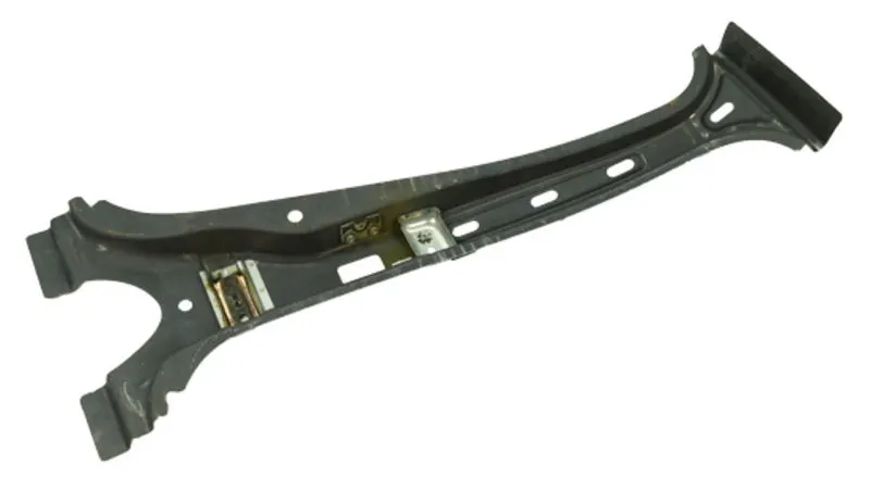
MASTER SECTION :
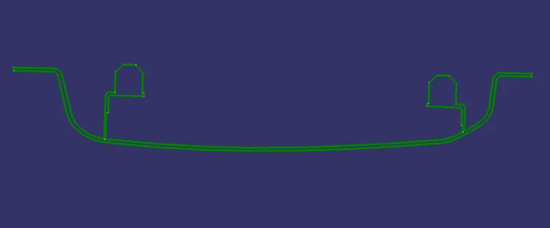
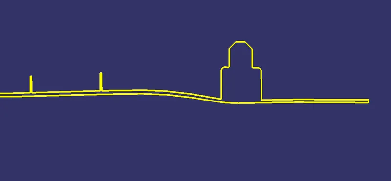
- Master section serves as a reference which was created to make new addtions or any changes to the existing component.
- The Master section mostly depends on the reference vehicle data and the experience of structure design engineers.
RIB :
- Rib is a feature which provides stiffness and strength to molded parts.
- They are thin extensions that run perpendicular from a wall or plane.
- They provide these features without increasinbg the overall thickness.
- If the wall is too thick, warping and sinking can result so that the entire design may need to be rejected.
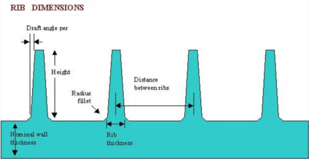
- Taller Ribs provide great support, Rib height might approximately taken as 5 times the base thickness.
- For wall thickness less than 1 mm, rib thickness is same as the wall thickness.
- A Draft of 0.5 degrees per side is the minimum limit.
- Rib thickess can be taken as 0.4 times the base thickness.
- Minimum thickness at the rib tip is 0.75 mm.
- Optimum rib fillet radius can be taken as 0.25 mm which is optional.
DOG HOUSE :
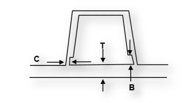
- Dog house is an engineering feature used in plastic trim design as supporting feature.
- A Draft of 1.5 degrees per side is the maximum limit.
- In case of a slide 3 degrees of Draft can be provided
- At the intersection part dog house wall thickness must me less than or equal to 40% of the wall thickness of the component.
- It's height should be between 3 and 6 mm.
LOCATORS :
- Locators are components present in plastic design which are used to hold the components in place.
- These are used to arrest the degrees of freedom of a component.
- The types of Locators include 4-Way locator and 2-Way locator.
- A Draft of 0.5 degrees per side is the maximum limit.
- The locator used here is a 4-way locator.
CLASS A SURFACE :
- Class A surfaces are those surfaces which are curvature continuous while providing the simplest mathematical representation needed for the desired shape and does not have any undesirable waviness.
- The Class A surface is the used to begin the design of a product.
- All the further intricacies of the component are created based on the Class A surface.

CLASS B SURFACE :
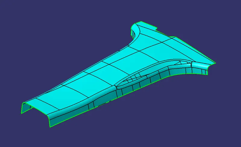
- The Class B surface is created from the Class A surface , keeping the thickness of the component in check.
- The Class B surface resembles an offsetted surface from the Class A.
CLASS C SURFACE :
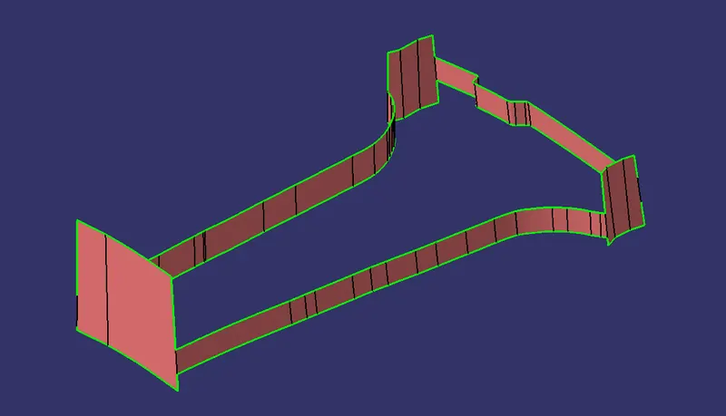
- The Class C surface is used to bind the Class A and Class B surface together inorder to form a closed surface.
PROCEDURE :
Creating Tooling Axis
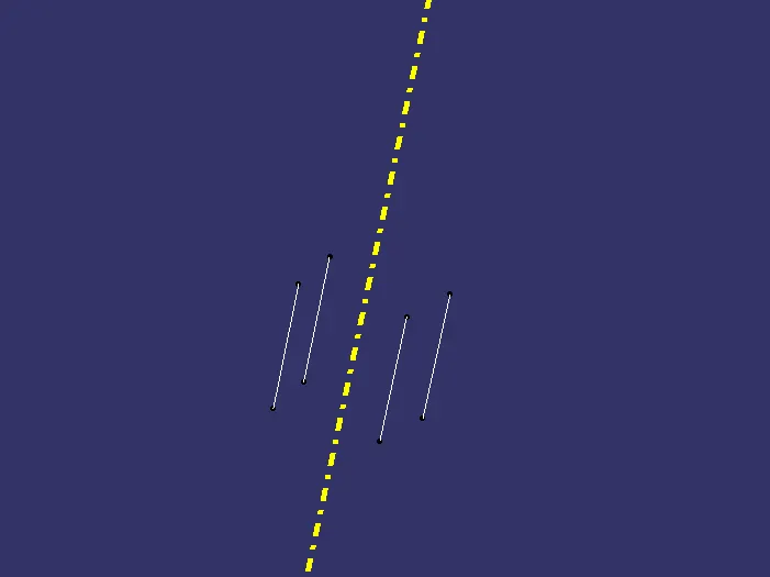
- Four lines were extracted from the master section, two from each curve.
- A center line was created using Bisecting option.
- Thus the main Tooling axis was created.
Creating Outer Flange for A surface
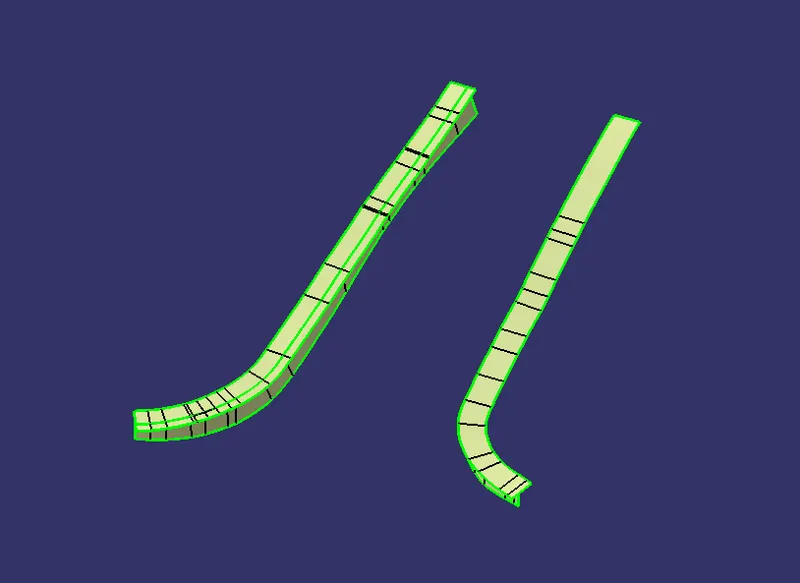
- The Class A which was provided did not contain the outer flange.
- In order to create the missing flange, initially the lateral surface of Class A was extracted along with its outer boundary.
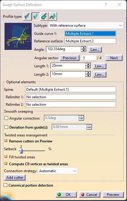
- Then the flange was formed using the Sweep surface feature with the option With reference surface using the extracted curve and the surface.
- An angle 0f 102.354 was given in order to match the master section which was provided.
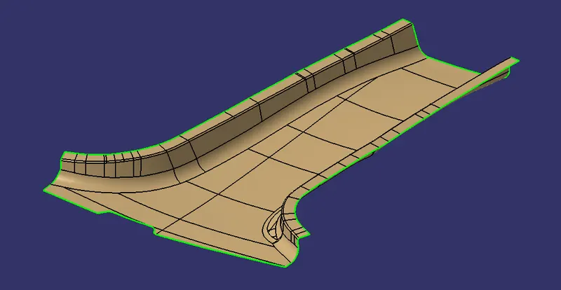
- The same procedure was performed on the other side as well.
- These flanges were then joined with Class A.
Creating Class B surface
- The Class B surface was directly offsetted from the Class A
- The outer flange was created separately for Class B as well.
- Here the outer boundary was extracted and extrapolated to form the flanges on both sides.
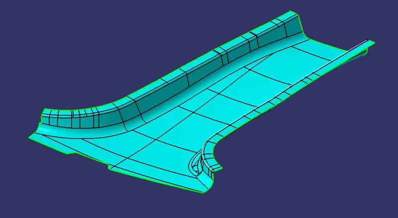
Creating Class C surface
- The boundary of Class A was extracted to form the Class C.
- The Sweep command was used along With draft direction, with a draft angle of 3 degree to form the C surface.
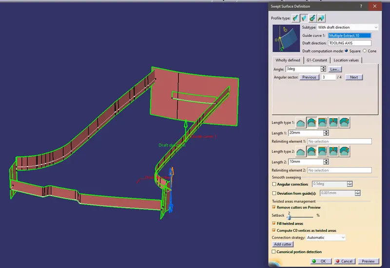
- This process was repeated to form a ring of surfaces, which were extrapolated to intersect eachother.
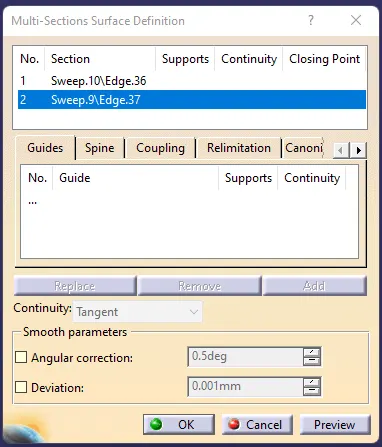
- At the corners, Multi sections surface feature was used to create the surfaces
- The necessary extrapolations were performed and the surfaces were Trimmed to form a single surface.
Creating Solid Body
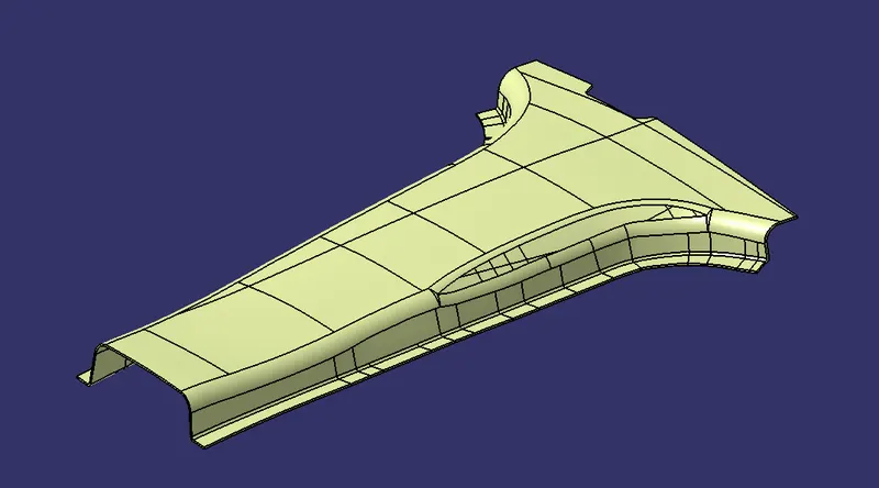
- Finally the Class A, B and C surfaces were trimmed together to form a closed surface.
- Using the surface created the solid component was obtained using the Close surface feature present in the part workbench.
- The Tooling axis, Class A, B and C surfaces were published.
Creating B side features using Master section
- The B side features were created using the Master sections as a reference.
Locator with Dog house
- Initially a plane was created using reference from the master section.
- Two perpendicular sketches were created matching the master sections and were extruded.
- The closing surfaces at the front and back were formed and they were Extrapolated to intersect and Trimmed.
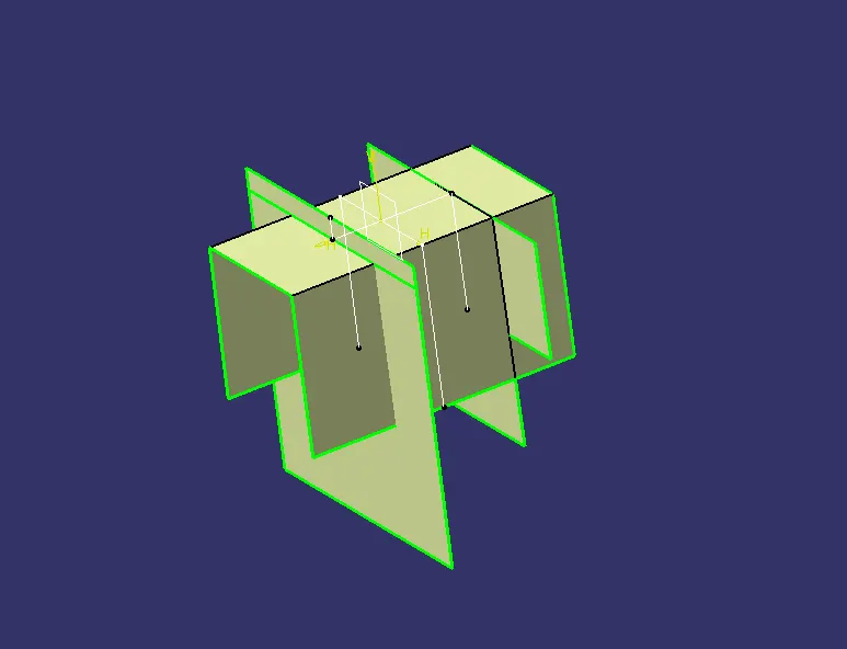
- An offsetted surface from the base was used to create the inner portion of the dog house.
- The necessary fillets were provided to the surface.
- An intersection part was created at the inner side of the dog house unit.
- A Draft of 0.5 degree was given on the inner side of the dog house.
- The entire surface was cut with the Class A to form the required shape.
- A second tooling axis was created perpendicular to the main tooling axis in the X direction inorder to accumulate the inner cavity of the dog house unit while machining which was known as the Lifter axis.
- Thus the Dog house unit was created.
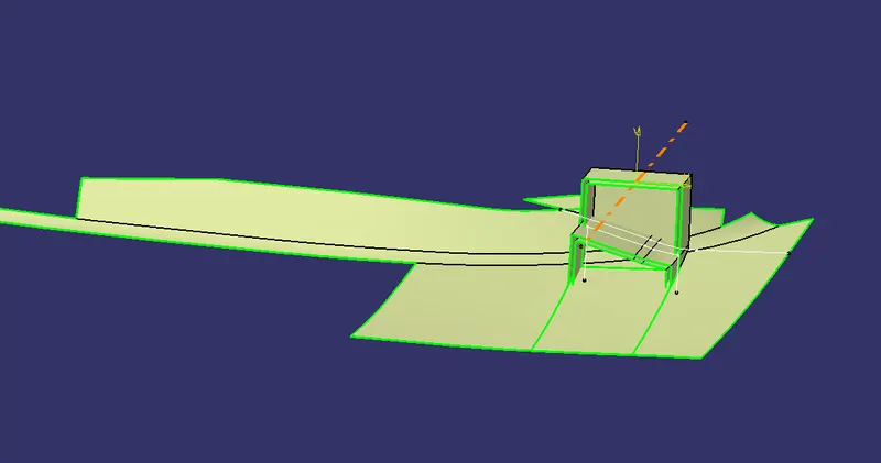
Locator
- A plane was created on top of the Dog house.
- A sketch for the rib was created on the surface and it was extruded using the thicken option in the pad command.
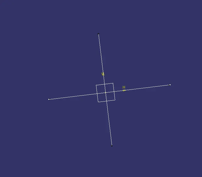
- The necessary fillets and chamfers were provided to this feature.
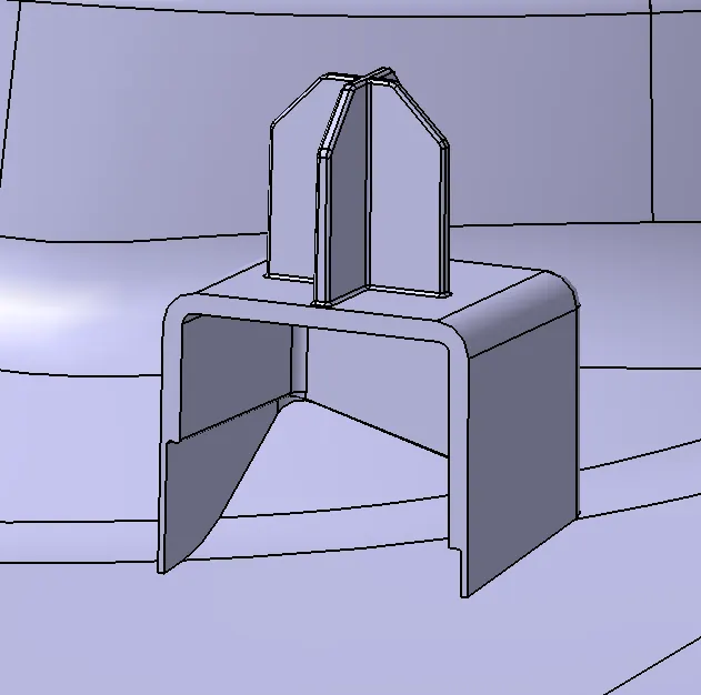
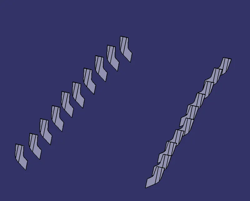
Ribs
- A rib shape was created using the surface which was extracted from the Class A.
- It was trimmed to obtain a proper shape.
- The Thick surface feature was used to form the ribs.
- The necessary drafts and fillets were provided to the ribs.
- Multiple ribs were created on both sides using the translate and mirror feature.
Draft Analysis
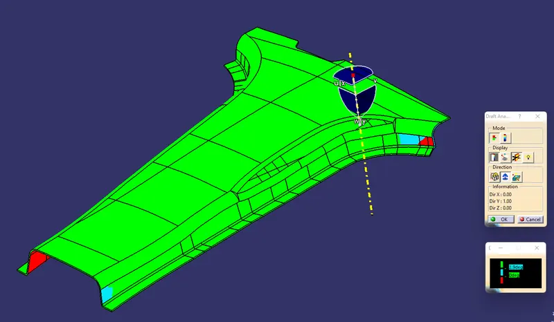
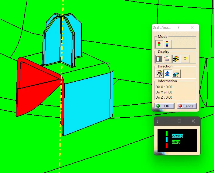
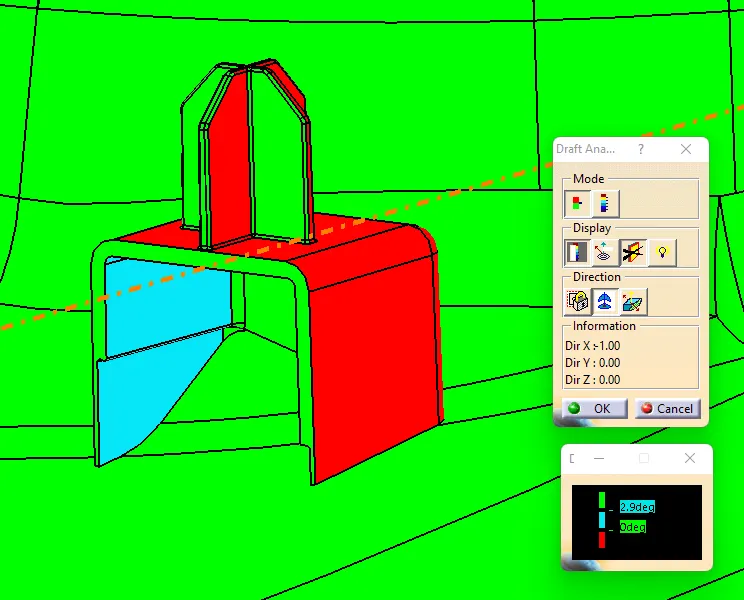
- The Drafting analysis was performed using the Feature Draft Analysis command.
- The Draft analysis was created with respect to both Tooling axis and Lifter axis.
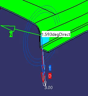
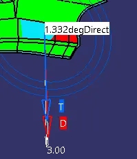
All areas have minimum 3 degree of draft except the areas shown below,
Inner side, All the ribs were clearing the required draft angle.
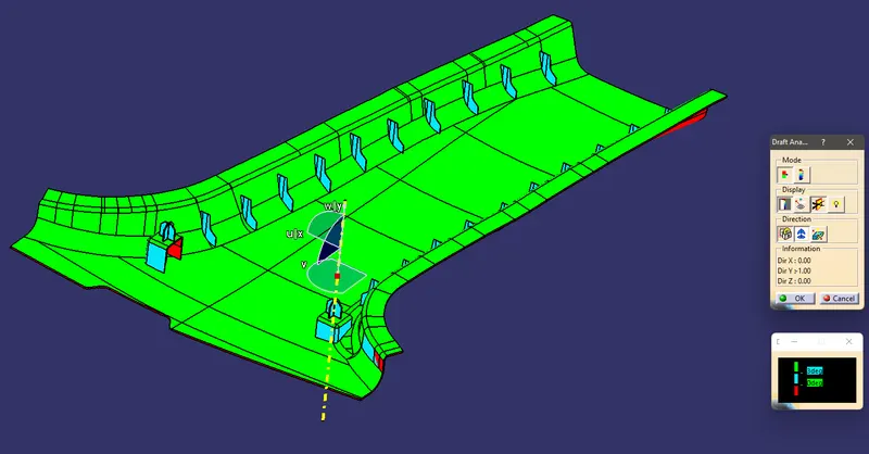
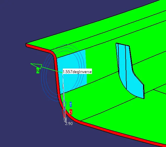
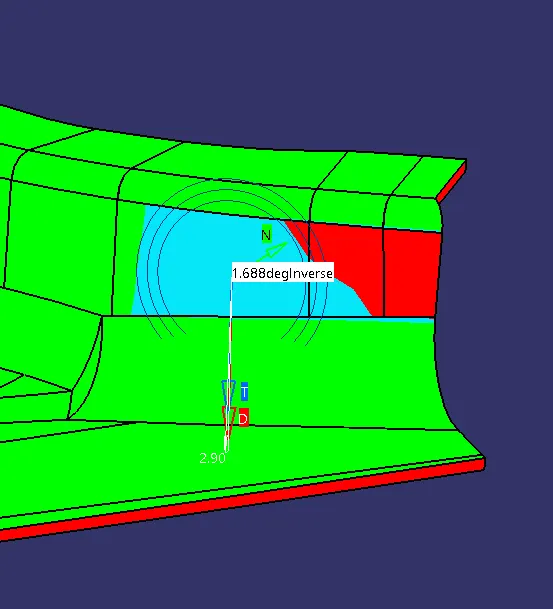
All the faces of the C surface follow the required draft angle.
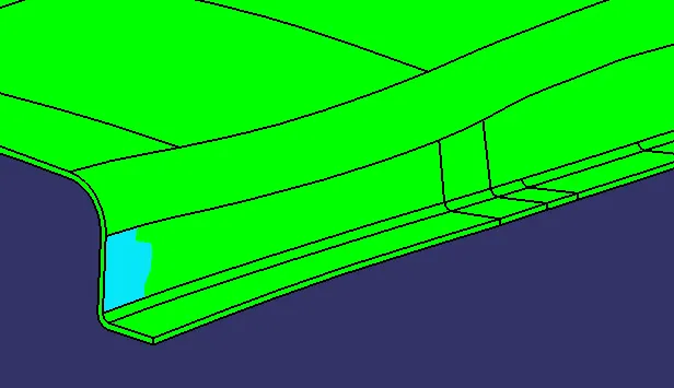
A minimum of 0.5 degree draft on the cyan faces and 3 degree on the green faces with respect to the Main Tooling axis.
A minimum of 0.5 degree draft on the cyan faces and 3 degree on the green faces with respect to the Lifter axis.
MODEL RESULTS :
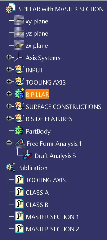
Feature tree
Front view
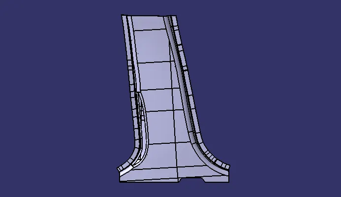
Top view
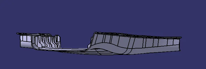
Side view
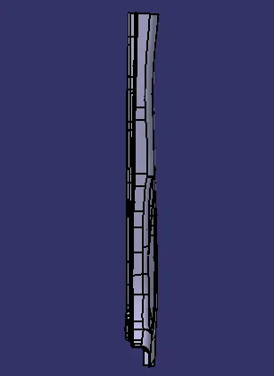
Isometric view
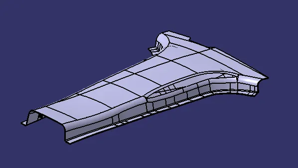
B side features
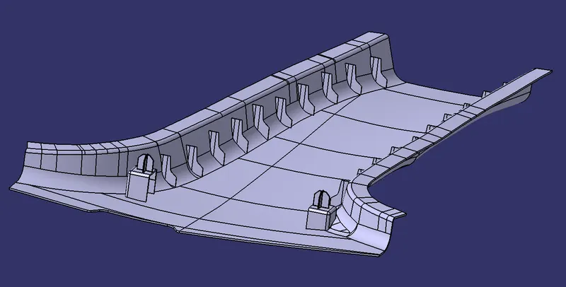
CONCLUSION :
- The Tooling Axis and the Lifter Axis for the component was created.
- The solid component was created from the surface geometry.
- The Screw boss and Dog house unit was created.
- The Rib features were created.
- The Draft Analysis was performed.
- Necessary images and files were attached.