BIW Fixture Design Methodologies
AIM :
To study about the various design aspects regarding BIW fixtures.
OBJECTIVE :
- To explain about Design Methodology.
- To state the inputs required from the customer to start designing a Fixture.
- To state the input we get from "Car Products".
- To explain about the Clamp plan.
- To state the purpose of a Layout.
- To brief on Ergo data.
- To elaborate on Weld study.
- To state the criteria for percentage completion in the designing stage.
- To brief about "Output" in design.
- To brief on structuring a design tree and the errors associated.
- To explain about Units and its types.
- To brief on Fixed Pin units.
- To state the different parts of a Fixed unit.
- To state the purpose of making a Rest unit.
- To define the basic fundamentals to design a Sensor unit.
- To explain about the Rough locator unit .
- To explain about the Base unit.
- To explain about the Dump unit.
- To explain about the Slide unit.
1. Design Methodology
Design Methodology is the steps followed during concept design stages of Fixture design.
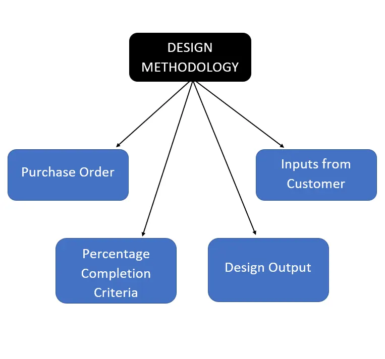
Purchase Order
- It is the order given by the customer which indicates the start of work.
Inputs from Customer
- These are the rquirements or specifications given by the customer which has to be taken into consideration during Design process.
Percentage Completion Criteria
Percentage completion criteria is followed in order to finish the process in a fixed time limit as required by the customer.
It is followed in the designing and dispatch stages of the entire process.
- 0 to 25 % - Input and concept design
- 25 to 40 % - Concept approval and simulation check.
- 40 to 85 % - Design freezing and detailing.
- 85 to 100 % - Checking and dispatch
Design Output
- Design output is the final set of files which are provided to the customer.
- It includes part files, 2D drawings, BOM etc.
2. Inputs required from the customer to start designing a Fixture
The various inputs required from the customer to start designing a fixture are as follows,
- Function Requirements
- Preferred Standard Components
- Car Products
- Layout
- Ergo Data
- Weld Study
- Standard Detailing Templates
Function Requirements
It states the purpose for which the fixture is to be designed.
Some of the fixtures include,
- Welding
- Hemming
- Checking
- Storage Racks
Preferred Standard Components
Standard components are used in the design to make the design process easier.
It saves time and effort which is required in making non-standard components.
Some of the standard parts include,
- Risers
- L Blocks
- Pins
- Retainers
- Cylinders
- Clamp units
Car Products
Car prodcuts are the data which helps in designing the fixture as per the requirements.
The various inputs include,
- 3D data
- GD & T
- Part list
- Clamp plan
- Product assembly part sheet
Layout
- Layout is the space which helps in understanding the flow of process in the entire assembly line.
Ergo Data
- Ergo Data refers to Ergonomics which is the study of the Human behaviour and movements.
- This data is provided by the customer based on the things such as loading height, fixture, working safety zone of operator.
Weld Study
Weld study includes the details of various entities such as
- Weld gun
- Weld matrix which includes geo spots and respot welds
- Weld points
Standard Detailing Templates
- Standard templates are provided to design the component in that direction and also maken the entire process easier.
- These templates are provided by the customer.
3. Inputs we get from "Car Products"
Car prodcuts are the data which helps in designing the fixture as per the requirements.
The various inputs include,
- 3D data
- GD & T
- Part list
- Clamp plan
- Product assembly part sheet
3D data
3D data consist nothing but the part files of the components involved in the fixture designing process.
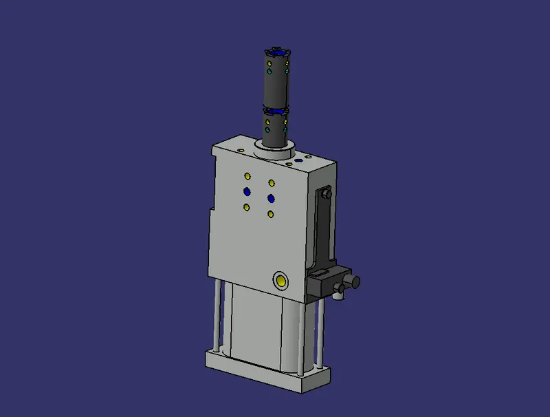
GD & T
GD&T is an acronym that stands for Geometric Dimensioning and Tolerancing.
It is a symbolic language used by designers to communicate manufacturing constraints and tolerances clearly.
It has the information of location positions, clamps, dumps and slide units.
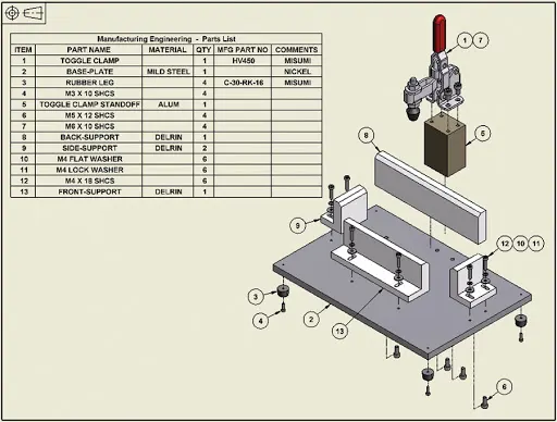
Part list
Part list consists of all the individual components present in the assembly.
These parts have a unique number which comes in handy during assembly process.
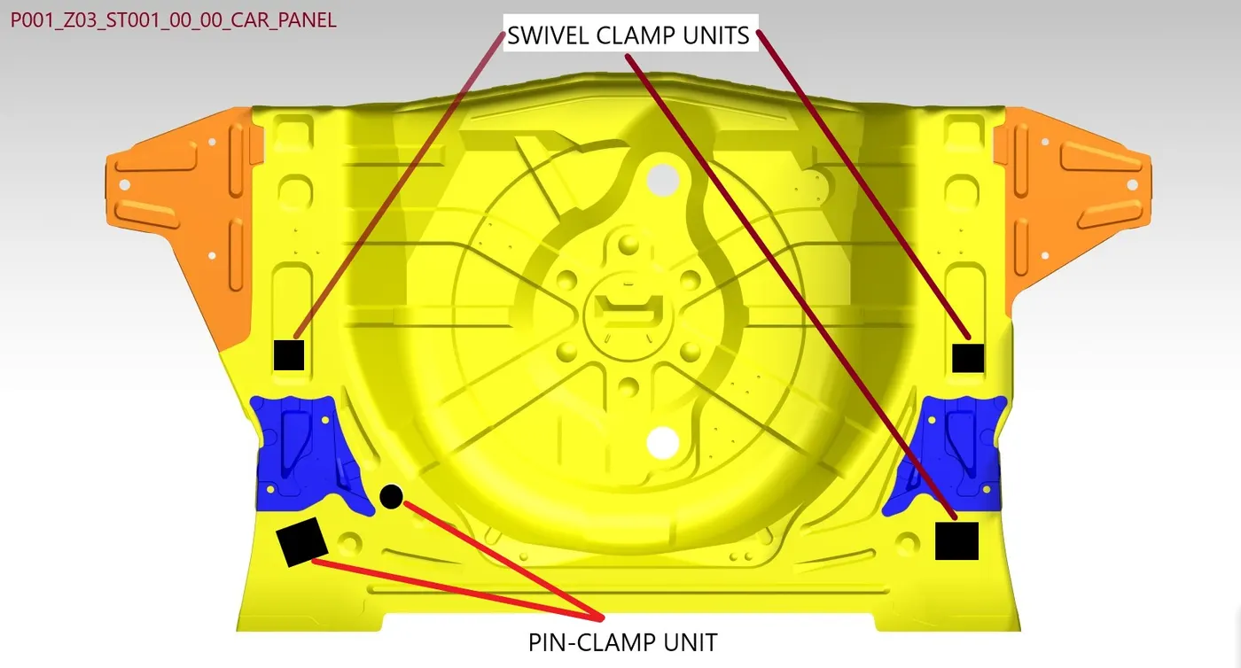
Clamp plan
Clamp plan provides the vital information which is the location of clamps in the component.
Product assembly part sheet
Product assembly part sheet contains the sequence in which the components must be assembled.
4. Clamp plan
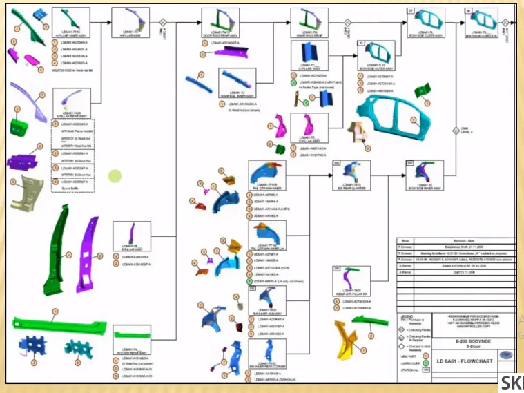
Clamp plan provides the vital information which is the location of clamps in the component.
Clamp position must be as per the clamp data and it must not be changed.
The clam plan consist of the positioning og the clamp unit and pin unit, these units must be designed according to the positions stated in the clam plan.
The clamp unit must not interfere with the other components.
Clamp must be designed in such a way that the operation time is minimum.
5. Purpose of a Layout
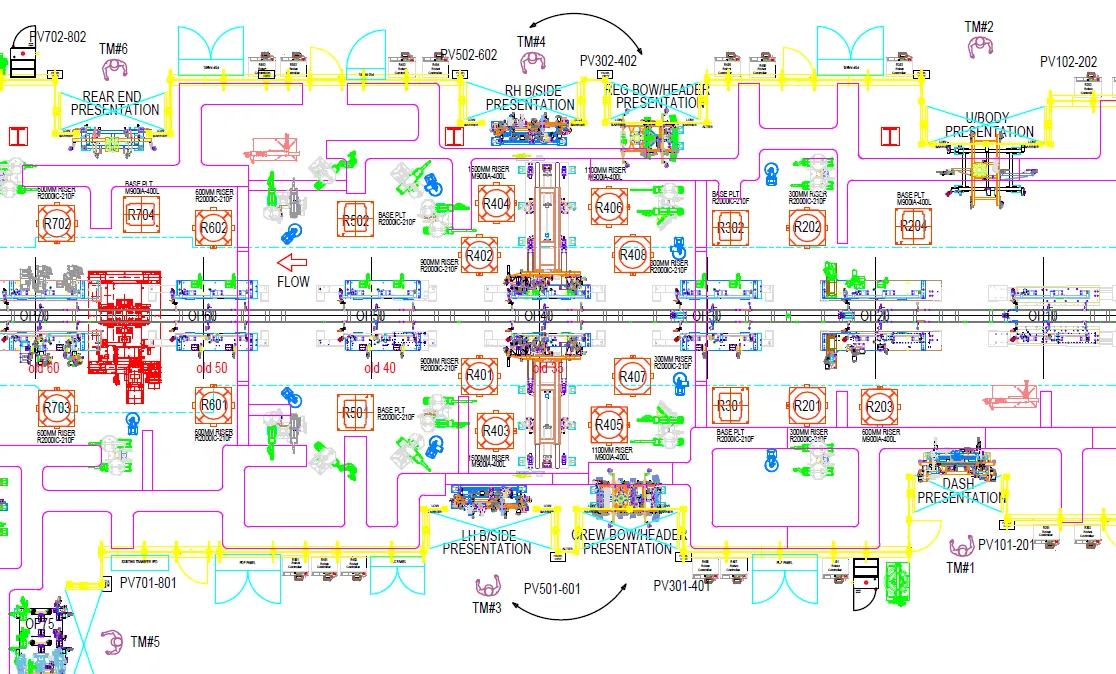
Layout is the space which helps in understanding the flow of process in the entire assembly line.
It provides the detailed vision of the of all the processes in the assembly line.
It also gives the information regarding the position of the fixtures and the robots working on it.
The swept area of a robot is generally indicated using a circle around it.
This area is known as Trapped area.
Some of the aspects provided in the layout are,
- Flow of parts
- Station pitch
- Robot stations
- Sub assembly link
6. Ergo data
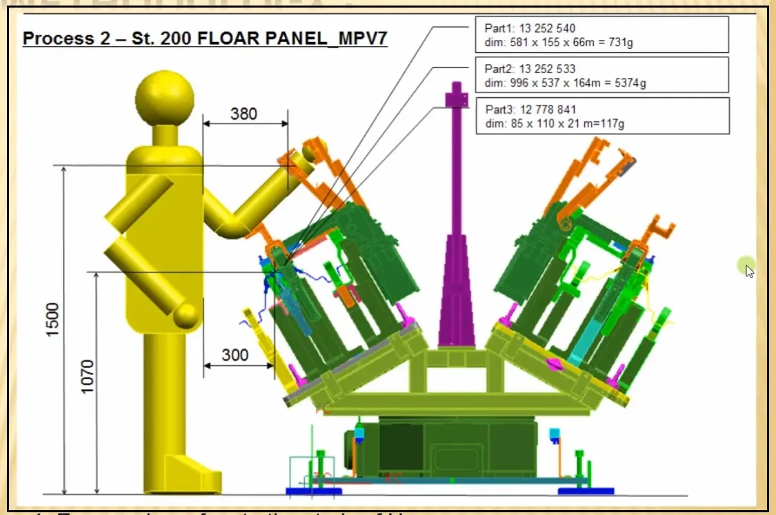
- Ergo Data refers to Ergonomics which is the study of the Human behaviour and movements.
- This data is provided by the customer based on the things such as loading height, fixture, working safety zone of operator.
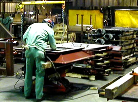
- Ergonomics can roughly be defined as the study of people in their working environment.
- More specifically, an ergonomist (pronounced like economist) designs or modifies the work to fit the worker, not the other way around.
- The goal is to eliminate discomfort and risk of injury due to work.
- Every company has their own standard ergo data, which the provide while designing the fixture.
- These data are to be considered while locating and designing the fixtures.
7. Weld study
Wel study is the study of the verious aspects which are required during the welding process.
It includes the position of welding, types of welds preffered , weld gun which is to be used etc.
Weld study includes the details of various entities such as
- Weld gun
- Weld matrix which includes geo spots and respot welds
- Weld points
Weld gun
This study is conducted to select the type of weld gun to be used for a particular location in the fixture.

Weld matrix and Weld points
Weld matrix and Weld points gives us the exact location where the welding process is to be performed.
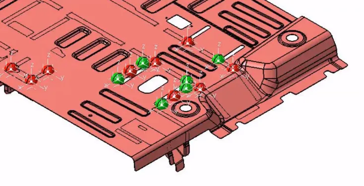
The weld points are further classsified as
- Geo spot welds - Red coloured spots
- Re-spot welds - Green coloured spots
8. Criteria for percentage completion in the Designing stage
Percentage completion criteria is followed in order to finish the process in a fixed time limit as required by the customer.
It is followed in the designing and dispatch stages of the entire process.
- Input and concept design
- Concept approval and simulation check.
- Design freezing and detailing.
- Checking and dispatch
Input and concept design
In this stage of the project 0 to 25 % of the project is completed, further the project is moved to approval and simulation section.
Concept approval and simulation check.
In this stage of the project 25 to 40 % and moved to design section.
Design freezing and detailing.
In this stage of the project 40 to 85 % of the project is completed.
Checking and dispatch
This is the final stage in the designing stage ,in this stage of the project 85 to 100 % of the project is completed.
9. "Output" in design
Design output is the final set of files which are provided to the customer.
It includes part files, 2D drawings, BOM etc.
- Standard components are to be used wherever necessary.
- Design must invole the the necessary safety features.
- The components must have a minimum weight with maximum strength.
- Design must ensure that the components must not interfere.
- Proper clearances must be provided in the assembly.
Outputs are generally classified as,
- Utilized tools
- Non - Utilized tools
Utilized tools
Utilized tool testing requires two types of sheets,
- Key sheet
- Layout sheet
Non - Utilized tools
Non - utilized tools are the stand alone tools which does not require any key sheets.
10. Structuring a design tree and the Errors associated
Structuring a design tree is the process of naming the various component present in the assembly in an organised manner.
It differ with various aspects according to the requirements and availability of the customer.
It helps identiy the zone, station and the component number in a particular assembly whicbh indeed reduces the errors associated with the manufacturing process.
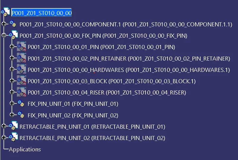
This type of detailing avoids the confusion associated with the designing.
It also helps in identifying the quantity of the components.
11. Units and its types
Units are a set if individual components assembled together to form a single unit to perform a specific function.
These functions include locating, clamping, providing support.
Units are classfied as,
1. Simple Unit
- Rest Unit
- Fixed Pin Unit
- Retractable Pin Unit
- Rough Locator Unit
- Sensor Unit
- Base Unit2
2. Complex Unit
- Slide Unit
- Dump Unit
12. Fixed Pin units
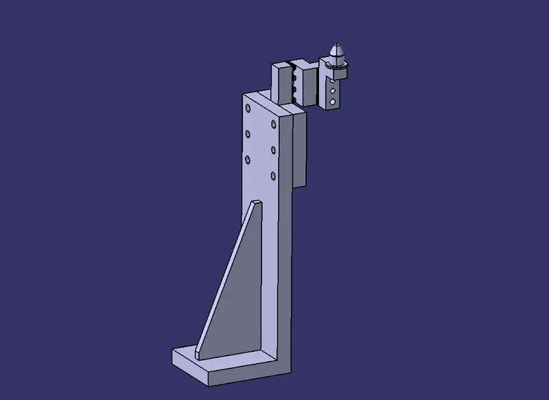
The Fixed pin unit is designed to locate the car pannel using different types of pins.
The main purpose of this fixed pin unit is to locate the component.
Two different types are used to achieve the proper locating of the required components.
They arrest 6 degrees of freedom of the component.
13. Different parts of a Fixed unit
The various parts of a fixed pin unit are as follows
- Pin
- Pin Reatainer
- Shims
- Block
- Blade / Adaptor plate
- Riser
Pin
- Pin should have grinding surface on shaft with fits on to which the pin retainer will be fitted
- The mounting surface of the pin should be a fine machined surface.
- The pin should have a step machine surface to lock the rotation, which matches with the pin retainer
- The mounting surface of the pin retainer to the blocks should be a machined surface. A
- All machined planes should be perpendicular to the axis of the pin shaft.
- Pin must have a fastening provision like tapped hole from the bottom or a V grove from the side
- A pin must be hardened (Heat treatment) and black oxide finished in general.
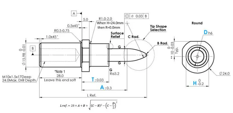
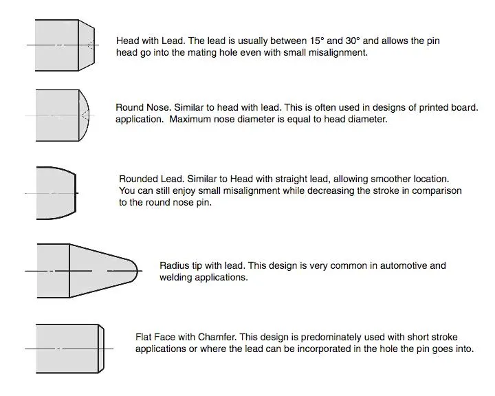
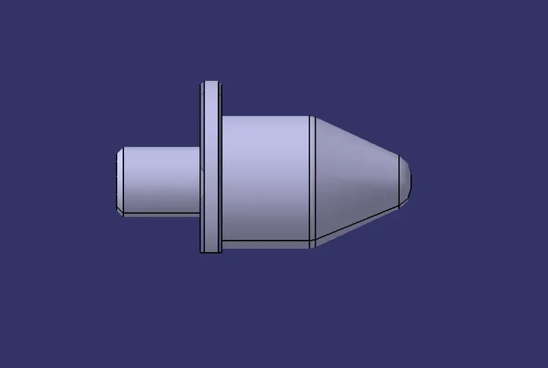
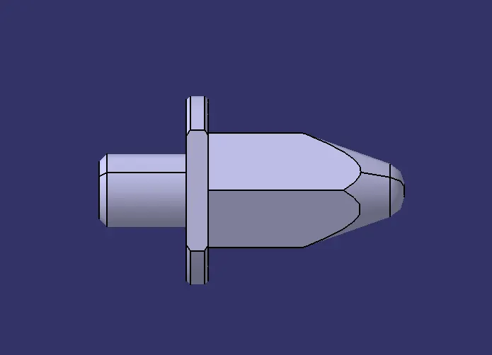
The two types of Pin units used were,
- Circular Pin
- Diamond Pin
Pin Reatainer
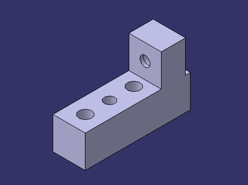
Pin Reatainer is a part which holds the pin in place.
It restricts the rotation of the pin mounted on it.
It can either be a make part or a standard part.
- Pin reatainer must contain a hole in it in order to mount the pin.
- The surface on which the pin is mounted must be a machined surface.
- It must contain a step to lock the rotation of the pin.
- The surface which is mounted with the blocks must be machined.
- It can be fixed with the riser using a block.
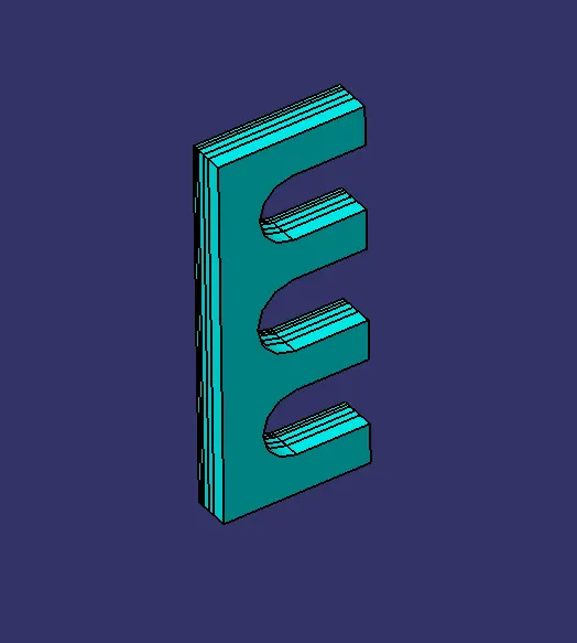
Shims
- Shims are used foe the adjustment of the locators.
- In generaal these are standard parts.
- Shim blocks can be adjusted according to the manufacturing deviations.
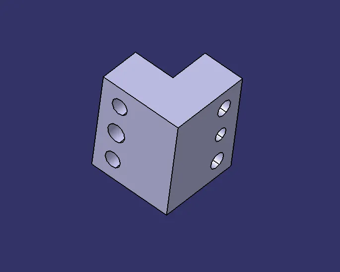
Block
- Blocks are generally used to accommodate the shimming directions.
- It is also used for the ease of design.
- Blocks can be of L shape.
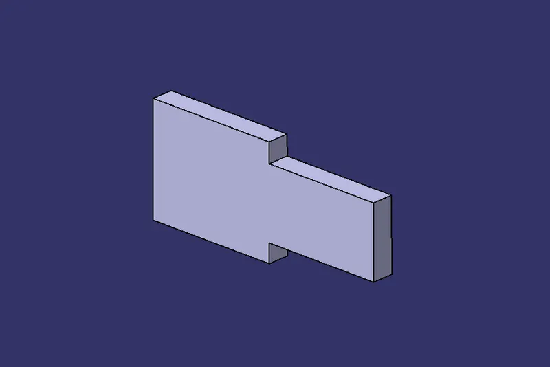
Blade / Adaptor plate
- Blade is the part which is used to connect the entire unit with the riser block.
- It can either be a make part or a standard part.
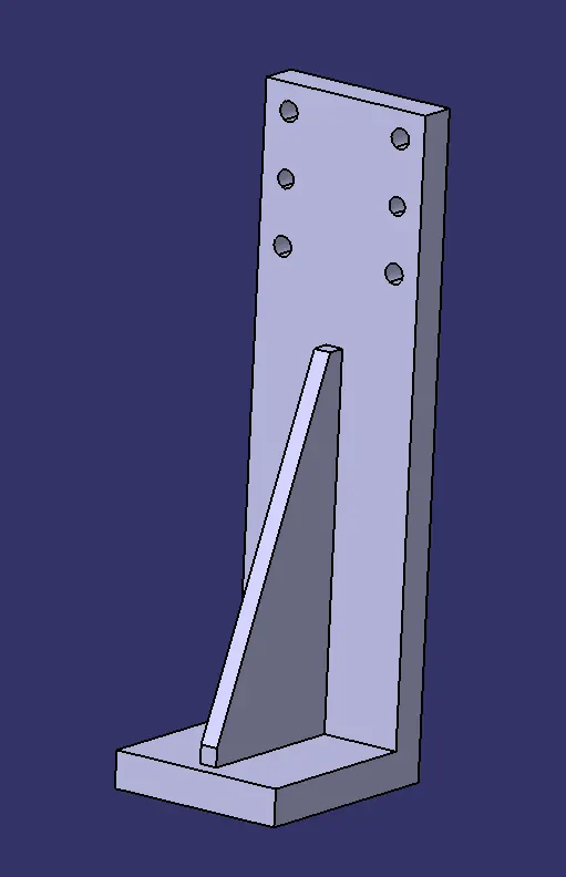
Riser
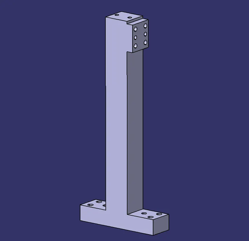
- Riser is the part on which the all the units are mounted.
- It provides support to the unit and attaches itself to the base.
- It can either be a make part or a standard part.
14. Purpose of making a Rest unit
A Rest Unit is used to support the entire car pannel from underneath.
It is a simple unit which used only used to support the panel.
In order to save the overrall cost, it can be combined with other unit such as locating unit.
The various parts of a fixed pin unit are as follows,
- NC blocks
- Shims
- Blade
- Riser
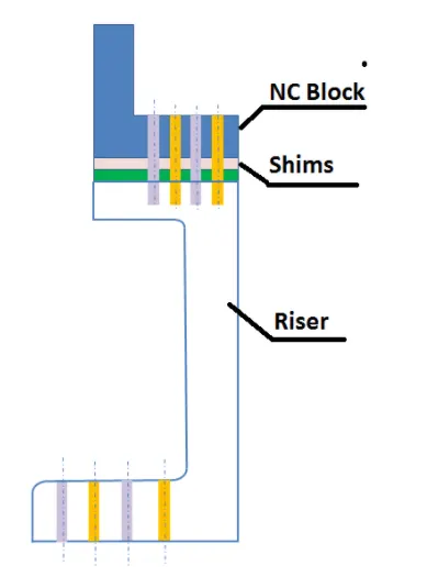
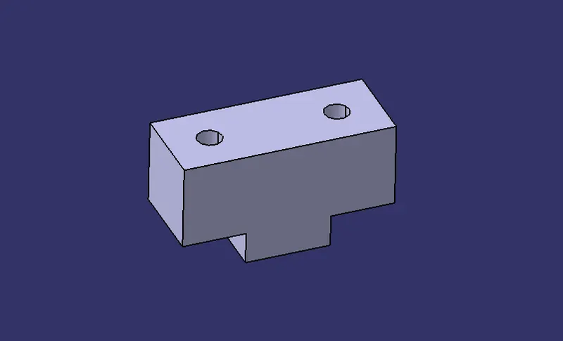
NC Block
- NC block is attached to the clamp arm of the cylinder.
- It used used to hold the car panel by pressing it against the rest.
- It is also known as Clamp Mylar.
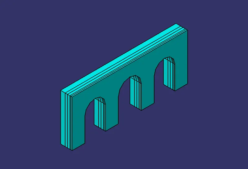
Shims
- Shims are used foe the adjustment of the locators.
- In generaal these are standard parts.
- Shim blocks can be adjusted according to the manufacturing deviations.
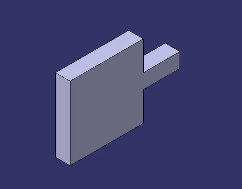
Blade
- Plate or Blade is an optional block which can be used according to the design requirements
- Blade is the part which is used to connect the entire unit with the riser block.
- It can either be a make part or a standard part.
Riser
- Riser is the part on which the all the units are mounted.
- It provides support to the unit and attaches itself to the base.
- It can either be a make part or a standard part.
15. Basic fundamentals to design a Sensor unit
A sensor is a device that detects and responds to some type of input from the physical environment.
The specific input could be light, heat, motion, moisture, pressure, or any one of a great number of other environmental phenomena.
Each component must be sensed in order to minimize the errors involved.
In general these sensors must be installed as a 3 direction adjustable unit.

Some of the sensor that are equipped in the BIW fixtures are,
- Laser sensor
- Proximity sensor
- Photoelectric sensor
16. Rough locator unit
Rough locators are used to help locate workpieces in the automation process.
Locating refers to the desired location where you want the workpiece to be when it is getting worked on either by a person, team, or robot.
It is a device to establish and maintain position of a part in a jig or fixture.
The various functions of a rough locator unit are as follows,
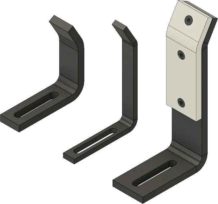
- It is used to guide the conponent to place it properly.
- It is generally placed at the edges.
- It must have an entry angle of 30 to 45 degree.
- It must guide the component at a distance of 10 to 15 mm before the engagement
- It is mounted on the base with slots for easy positioning.
17. Base Unit
Base Unit is one of the most significant unit of the fixture design because the entire fixture assebmly is mounted over it.
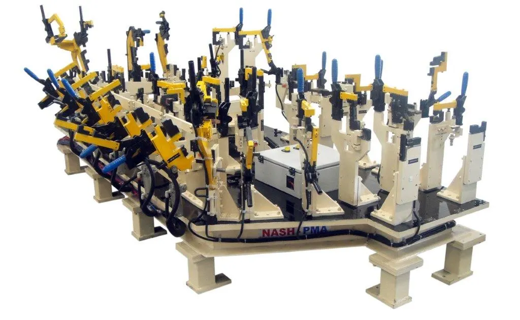
The various parts of a Base Unit are,
- Base Plate - Base plate is a machined plate of 25 to 40 mm thickness generally made up of steel and aluminium.
- Pedestal - A pedestal is a part which connects the base plate to the floor plate.
- Trucking channel - A trunking channel is a duct which accommodates all the pneumatic and electrical hoses and wires for the units of the tool.
- Valve box - Valve box is a standard part which will accommodates the pneumatic valves for the units.
- Eye bolt - Eye bolts are used for the transporting of the tool from one plate to another using lift hooks.
- Floor plate - Floor plate is grouned to the floor with fixed bolt on the ground.
- Weld bar - Weld bars are be used to weld the positions permanently , after levelling is done.
18. Dump Unit
Dump Unit is similar to fixed pin unit which is used in case of intricate arrangements of the fixtures.
When the panels are hard to reach, fixed pin units are difficult to install during this situation Dump units are used.
Dump unit can have more than one cylinder to perform such a process.
The first cylinder dumps the assembly carrying clamp mylar, pins and retainers.
The panel must be easy to remove in the open position.
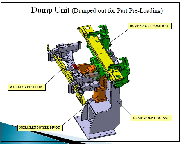
The various functions of Dump unit are,
- To fix the panel properly and ensure that its motion is restricted.
- To ensure that there is enough clamping force in the cylinder to with stand the welding process.
- Proper shimming must me provided to the panel.
- The rotation of the panel is restricted using side blocks or magnets.
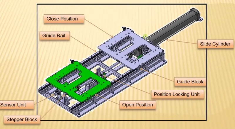
19. Slide Unit
- Slide Unit is a unit which is used to position various components.
- It is used in the mounting of various units in the fixtures, weld gun etc.
- During the operation, a particular unit is mounted n the slide unit and it is slides forward to reach the desired location.
- Once the operation is performed, it slides back.
- This sliding motion is achieved with the help of a cylinder.
- It also consist of sensor unit and stopper blocks to regulate the sliding motion.
CONCLUSION :
All the given objectives were satisfied with atmost perfection.
The images were attached wherever necessary